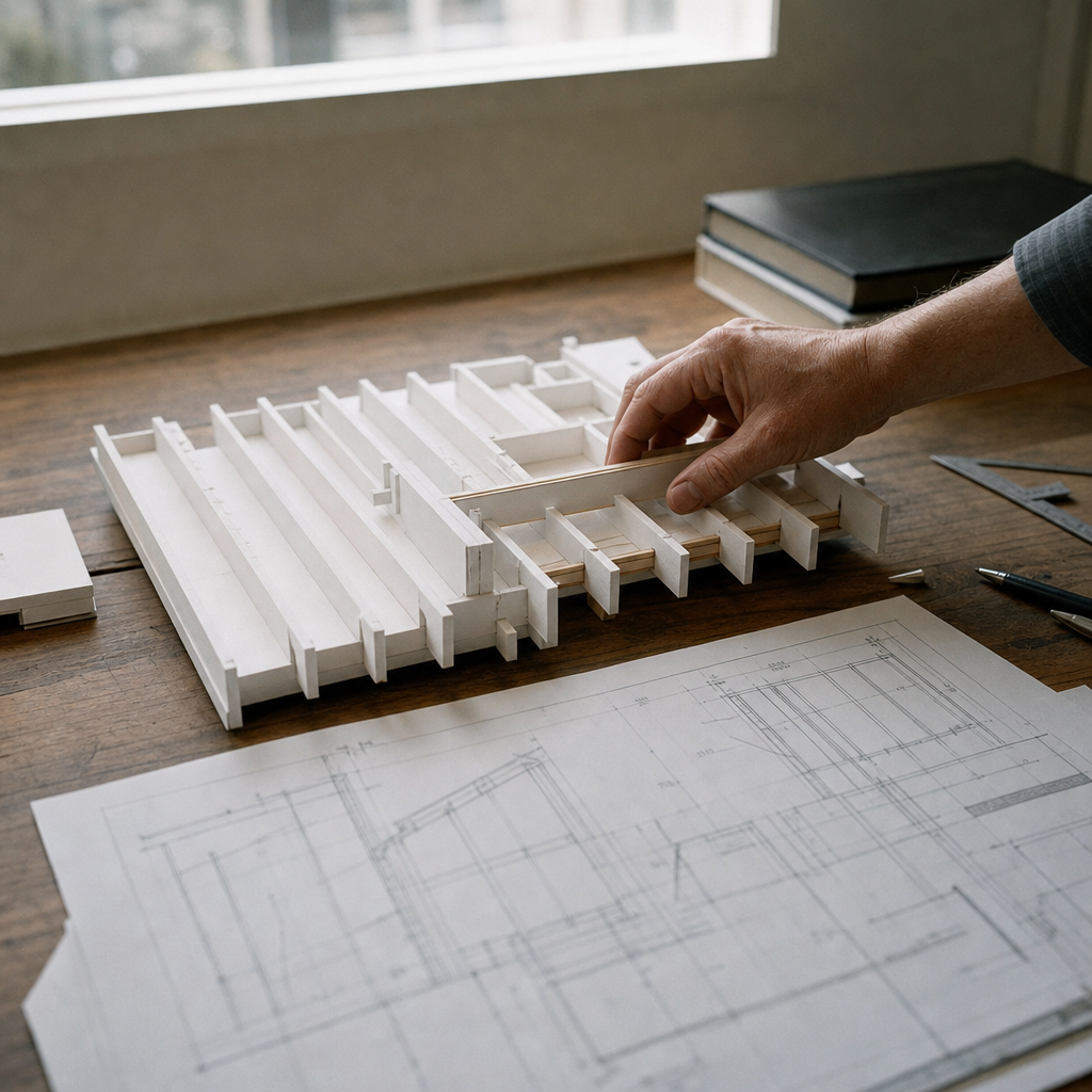
Stair openings in residential floors present some of the most demanding detailing requirements in Alberta wood-frame construction. Alberta Building Code (2023 NBC(AE)) Part 9 governs the layout, sizing, fastening, bearing, load path, and connection of headers, trimmers, blocking, and specialty hangers at these floor openings. Construction documentation must resolve code, municipality, and engineering requirements into clearly dimensioned and annotated plans and details. Redlines at plan-review and field phase most often stem from compliance gaps between code intent and drawing execution-not from unclear homeowner questions or product literature, but from plan sheet layout, note specificity, and connection call-outs. The following details how stair opening structural framing is drafted in Alberta residential floor plans and details, focusing on code translation, dimensioning, connection specs, response to plan-review redlines, and jobsite QA/QC.
ABC Part 9 Code Compliance for Floor Opening Framing: Translating 9.23.8.3, 9.23.8.4, and 9.23.5.3 into Dimensioning and Notes
9.23.8.3 Built-up Wood Beams: Ply Count, Fastening, and Grading on Plan Sheets
Section 9.23.8.3 of the NBC(AE) 2023 requires built-up wood beams, including stair opening headers, be specified by:
- Number of plies (laminations)
- Grade and size of each member (e.g., 38x235 mm, SPF No. 1/2)
- Fastening schedule (size, type, spacing, and pattern of fasteners)
The plan set should include explicit dimensioned call-outs for each header, for example:
- “HEADER: (3) 38x235 mm SPF No. 1/2; Nail w/ 82 mm common nails @ 450 mm o.c. staggered, per NBC(AE) 9.23.8.3.”
Correct call-outs avoid plan review delays for “Provide complete specifications for built-up wood beams, including member sizes, fastening methods, and material grades, per NBC(AE) 9.23.8.3.” Schedules or notes referencing only “as per code” do not satisfy permit reviewers or site crews. Built-up members must have all fastener rows and spacing detailed to enforce composite action through the thickness of the header at the stair well edge.
9.23.8.4 Steel Beams: Material, Sizing, and Sheet Coordination
When steel is specified (often to accommodate longer stair opening spans or reduced member depth), section 9.23.8.4 mandates:
- Material standard (CSA G40.21 or ASTM A992, e.g., W200x21, 350W)
- Full depth dimension, shape, and specification of bracing
- Coordination of beam end bearing and any required fire protection or corrosion-proofing
Plan sheets must place steel beam call-outs alongside wood framing notes, using clear tags-for example:
- “STEEL HEADER: W200x21 350W, bearing per 9.23.8.4, see Detail 4/S2.1 for connections.”
Omission of steel section or material grade will result in redlines such as, “Provide steel beam size, grade, and applicable standard as per NBC(AE) 9.23.8.4.” All related connection details must reference proprietary hangers or engineered seat designs, supporting a holistic review.
9.23.5.3 Wall Stud Notching and Drilling: General Notes and Section Details
Stair openings often align with walls where studs are notched or drilled to accommodate headers or MEP runs. Section 9.23.5.3 strictly limits:
- Notch depth to one-third the stud depth, centered within the half-depth of the stud near bearing edges
- Hole diameter to one-quarter the stud depth, offset minimum 50 mm from either edge
Section or elevation notes should read:
- “ALL NOTCHING OR DRILLING OF WALL STUDS TO COMPLY WITH NBC(AE) 9.23.5.3; REINFORCE WHERE NOTCHES OR HOLES EXCEED LIMITS.”
Detailed wall sections at the stair well should show the exact location, size, and reinforcement details for penetrated studs-especially for electrical chases along stair enclosure walls.
Coordination with STANDATA, Plan Review, and Long-Form Notes
Alberta STANDATA interpretive bulletins may further clarify province-wide or local variance to the above code sections. Plan review commonly returns comments such as:
- “Detail notching and drilling of wall studs to ensure compliance with NBC(AE) 9.23.5.3; specify reinforcement methods if applicable.”
- “Reference STANDATA 14-FCB-003 for any alternate engineered details integrated with proprietary beams.”
Long-form general notes are essential for capturing code compliance across plan set sheets and cross-referenced details. Failure to reference both code and STANDATA leads to avoidable hold-ups at plan-check and site review phases.
Standard Plan-Set Mechanics for Stair Opening Details: Clearances, Dimensioning Standards, and Annotation for Headers, Trimmers, and Blocking
Dimensional Clarity: Clearances, Headroom, and Framing Layout
Section 9.8.7.1 (NBC(AE) 2023) requires a minimum 2,050 mm headroom clearance measured vertically from a line drawn through all stair tread nosings. Plan sets must not merely dimension the floor opening, but locate and annotate clear headroom through stairs and at landings. The following sheet annotation is standard on A-series plans and interior sections:
- “HEADROOM CLEARANCE: 2,050 mm MIN FROM TREAD NOSINGS” (dimensioned on stair sections and reflected floor plans)
Failure to dimension headroom warrants typical permit-office comments:
- “Verify headroom to lowest ceiling point at landing and along all treads between floors.” (kingswaydrafting.ca)
Floor plan dimensions should extend to inner and outer faces of headers, not just rough opening dimensions, using “Header to Header,” “Header to Wall,” and “Landing Edge” markers.
Component Specification: Annotating Headers, Trimmers, and Blocking
Every structural member at stair openings receives an explicit material, grade, and size call-out. Common conventions include:
- “HEADER: (2) 38x285 mm SPF No. 1/2, see S4.1/Detail 6”
- “TRIMMER (JACK): 38x184 mm SPF No. 2”
- “CRIPPLE STUDS @ 400 mm o.c. BLOCKING: 38x89 mm SPF No. 2, BETWEEN JOISTS AS SHOWN”
Where trimmers bear primary loads, especially for clear openings exceeding 1,200 mm, they are doubled (per NBC(AE) and Calgary municipal advisories). A typical reviewer note reads:
- “Header joist spanning over 1.2 meters must be doubled and sized to support incoming floor joists. Please revise header details accordingly.”
Section and Detail Cross-Referencing
Plan sets must use consistent bubble and tag systems to call out connection and load path details, for example:
- “SEE DETAIL 3/A5.1 FOR HEADER-TO-TRIMMER CONNECTION”
or
- “SEE FRAMING PLAN 2/S2.1 FOR TRIMMER SUPPORT, AND SECTION 4/A6.2 FOR BLOCKING LAYOUT.”
This coordination ensures clarity for both permit reviewers and site framing crews. The most common redline for poor cross-referencing: “Load path from header through trimmer joists to supporting structure is unclear. Provide detailed section showing continuous load transfer.”
Infill, Guards, Blocking, and Code-Related Annotation
Section 9.8.8.5 requires stair opening guards to resist the passage of a 100 mm diameter sphere. Drawings must annotate this requirement, for example:
- “GUARD INFILL: SPACING TO PREVENT PASSAGE OF 100 mm DIA. SPHERE (ABC 9.8.8.5)”
In both detail and plan sheets, stair opening blocking must be coordinated for direct support of guard posts, mechanical chases, or firestopping at floor/ceiling interfaces. Every blocking member should have minimum material grade and size called out in the schedule or within a key detail bubble.
Detailed Connection Specifications for Headers and Trimmers: Joist Hanger Selection, Nailing Schedules, and EWP Integration
Joist Hanger Selection: Proprietary, Sized, and Clearly Called Out
Section 9.23.14 and 9.23.3 (NBC(AE) 2023) require that stair opening headers and trimmers joined to floor joists be secured using proprietary joist hangers-especially when the depth or load exceeds nail-only support. Plan and detail sheets must explicitly specify:
- Manufacturer and model number: e.g., “SIMSPSON LUS28Z HANGER, CCMC 12345-L”
- Exact size compatibility (width and depth match to EWP or dimensional lumber joists)
- All nail holes filled with manufacturer-required nail (not substitute or generic nail sizes)
- Orientation (hangers square with joist, attached to face or end as per manufacturer)
Where EWPs (I-joists, LVL, glulam) are used, hanger and connector specs must be coordinated with the engineered drawings. Failure to match model # or omit fastener patterns commonly yields:
- “Omission of proprietary connector specifications; submit manufacturer and model for all joist hangers at stair opening.”
- “Incorrect fastener types or sizes specified for EWP connectors; revise per supplier’s installation manual.”
Nailing Schedules: Code-Compliant, Dimensioned, and Staggered Patterns
Section 9.23.3 details fastening for built-up headers:
- “82 mm common nails in two rows, staggered, spaced no more than 450 mm apart” through all plies at built-up headers and trimmers (headers at stair openings typically being (2) or (3) 38 mm plies)
Drawing call-outs should mirror code, e.g.:
- “BUILT-UP HEADER: (3) 38x235 mm SPF No.1/2; Nail w/ 82 mm common nails @ 450 mm o.c. staggered, per NBC(AE) 9.23.8.3 and 9.23.3.”
Header ends must be face-nailed to adjacent trimmers and king studs with no less than 2 x 82 mm nails per member. Where LVL or other engineered lumber is used, nailing must follow the manufacturer’s schedule-often requiring additional face or toe-nailing, or proprietary screws. Failure to comply draws redlines such as:
- “Insufficient nailing patterns for built-up headers; stagger 82 mm nails per code and manufacturer.”
A connection legend or schedule on structural sheets is best practice, listing each fastener type and spacing for all stair opening members.
Engineered Wood Product (EWP) Integration at Stair Openings
The widespread use of I-joists, LVL, LSL, and glulam members in Alberta framing requires code-conforming and manufacturer-tested connectors. For framing stair openings in EWP floors:
- I-Joists: Use manufacturer-specified joist hangers with full-width/height support. End bearing and web hole locations must follow shop drawings. Drawings must reference, for example: “Joist hangers to be ‘Trus Joist JHI’ or equivalent; install as per EWP supplier’s shop drawings.”
- LVL: Where doubled as headers or trimmers, fasteners and blocking must prevent splitting and accommodate full load width. Detail: “All LVL header nailing per EWP manufacturer; min 3 rows 82 mm nails @ 300 mm o.c.” Common call-out: “LVL header to trimmer, face nail with 3 rows 82 mm nails @ 300 mm o.c.; refer to shop drawings.”
- Glulam: Proprietary top-flange or saddle hangers may be required, per engineered specs. All connections must be shown in detail bubbles and have approved load ratings detailed. For example: “Glulam header/hanger, see Detail 7/S4.2; all connectors per CCMC listings.”
Every EWP requires full shop-drawing cross-reference, fastener compatibility (e.g., not using standard bright nails with treated wood web stiffeners or exterior assemblies), and clear schedule layout linking product to detail number.
Material Compatibility and Code-Driven Moisture Protection
All connectors in contact with preservative-treated wood (especially when stair opening framing runs to a foundation or exterior wall) must be specified as galvanized or otherwise corrosion-protected (see NBC(AE) 9.23.3.4). Spec notes should read:
- “All connectors in contact with treated wood to be double-dipped galvanized or stainless steel, per CSA B111.”
Any wood-to-concrete bearing points require vapor/moisture separation, detailed for site clarity:
- “Provide 0.05 mm polyethylene or Type S roofing felt between wood and concrete at all bearing.”
This shields headers and trimmers from premature failure due to hidden condensation or foundation leaks. Review comments on missed protection read: “Specify moisture barrier beneath any wood member in direct contact with concrete, per NBC(AE) 9.23.3.4.”
Common Plan Review Redlines and Revisions for Stair Opening Framing: Addressing Deficiencies in Bearing, Sizing, and Load Path Specification
Double Headers and Trimmers on Spans Above 1,200 mm
The ABC, through NBC(AE) 9.23 framing requirements, requires double trimmers and headers when stair opening spans exceed 1,200 mm (approximately 4'-0"). Plan reviewers frequently redline single 2x12 or 2x10 headers at wide stair wells:
- “Header joist spanning over 1.2 meters must be doubled and sized to support incoming floor joists. Please revise header details accordingly.”
Framing plans should explicitly dimension these members (e.g., “(2) 38x235 mm SPF No. 2 header, each side of stair opening” with cross-section showing load path).
Bearing at Joist and Header Ends: 38 mm on Wood/Metal, 89 mm on Masonry/Concrete
Sectional details must provide explicit notes-and detailed section markers-at every bearing point. Header and joist ends must bear:
- A minimum of 38 mm on wood or metal
- A minimum of 89 mm on masonry or concrete
Where joist hangers are used rather than direct bearing, the hanger spec must be called out and approved for specified load (e.g., “Simpson LUS28Z; max factored load 8.8 kN per shop drawing, bearing where direct bearing is less than code minimum.”)
Plan review frequently finds:
- “Joist ends must have a minimum bearing of 38 mm on wood or metal supports. Ensure all joist bearings meet this requirement.”
and
- “Specify joist hangers at all locations where bearing is inadequate; provide manufacturer, model, and nailing pattern.”
Clear Load Path Specification
Continuous load transfer-from floor joists through header to trimmers and then to foundation-must be clearly illustrated in enlarged bay details and/or A-series section bubbles. Opaque notes such as “support as required” are insufficient and inevitably elicit:
- “Load path from header through trimmer joists to supporting structure is unclear. Provide detailed section showing continuous load transfer.”
Correct drawing conventions include exploded axons or sequenced step-section call-outs, with all posts, beams, and supporting foundation visible and labeled with size, material, and cross-referenced to schedules.
Detail Schedules and Tracked Revisions
Each plan revision must include a tracking schedule, ensuring plan reviewers can cross-reference all changes to header size, location of additional trimmers, connection upgrades, or bearing changes. Good practice is to add a revision cloud and tag (e.g., “Rev 2/12 July 2024-Header/Trimmer upgraded; see Details 4/A6.3”) and update the general notes accordingly.
City of Calgary and Local Amendments for Fire Protection Near Unenclosed Stairs
Openings near unenclosed exterior stairs invoke City of Calgary advisory B23-012, mandating additional fire protection measures. Plan sheets must:
- Dimension the distance from opening to exterior stair
- Annotate any required fire-resistant materials (Type X drywall, mineral wool, or fire caulk at penetrations)
- Provide detail bubbles tying firestopping to ULC design numbers and/or manufacturer listings
No note or call-out regarding fire-protective covering at these interfaces is a quick trigger for “Protection of openings near unenclosed exterior stairs per Calgary Advisory B23-012 missing or incomplete.”
Jobsite Call-Outs and Construction QA/QC Notes: Verifying Hanger Installation, Clear Opening Dimensions, and Firestopping Requirements
Hanger Installation Quality: Fastener Counts, Model No., and Inspection
Jobsite checks for stair opening hangers concern compliance with the specification and manufacturer’s requirements. Each hanger must:
- Match the joist and header configuration specified in the plan schedule (“Simpson LUS210, for 2x10 SPF, CCMC 12345-L”)
- Be installed per manufacturer’s instruction, using only listed fasteners (no substitution)
- Fill every nail/screw hole provided, unless plans or installation spec state an exception
Inspection notes and on-site checklists should echo the construction document call-outs:
- “All joist hangers installed with manufacturer-supplied nails; no undersized fasteners permitted.”
- “Hangers to be flush to face of header/trimmer; reject and reinstall any bent or off-plumb hardware.”
QA/QC checklists can reference NBC(AE) 9.23.6.3 for spacing and support; poor installation triggers site observations such as “Replace all hangers lacking full fastener count, model per plan, or with visible deformation.”
Clear Opening Dimensions: Field Verification and As-Built Recording
Section 9.8.7.1 (headroom) and plan-set-dimensioned “Clear Opening” lines serve as field-verification checkpoints. Trade foremen or inspectors must confirm:
- Stair opening rough opening measured from finished face of trimmer/header is as per plan (e.g., “R.O. 965 x 2750 mm”)
- Headroom projection measures at least 2,050 mm vertically from tread nosings at all points
QA notes on plan sheets often read:
- “Verify rough opening matches dimensioned plans prior to stair framing. Notify architect of any discrepancies or site modifications for as-built update.”
Non-conforming headroom after framing is costly; recording “as-built” dimensions in field-marked shop drawings reduces CO delays and rework risk.
Firestopping of Stair Opening Penetrations and Adjacent Assemblies
Section 3.1.9.1 mandates all penetrations of fire-rated separations at floor openings, especially for multi-unit structures or suites over garages, be firestopped with tested systems (CAN/ULC-S115). Drawings should:
- Reference tested firestop system (ULC Design No. or manufacturer product)
- Specify product, install method, and rating equal to or greater than that of the assembly (e.g., “3M FB-3000 WT, install per ULC 2B26; F rating: 1.5 hours”)
- Show material type symbolically in plan and detail (often a “fire caulk cloud” or hatch at penetrations)
- Assign QA note: “All firestopping to be installed by licensed installer per tested detail; provide certification at inspection.”
The most frequent QA redlines are:
- “Unsealed penetrations through gypsum assembly in stair opening; install tamperproof firestopping per plan call-out.”
- “Provide ULC test documentation for all firestopped penetrations at stair opening.”
Jobsite control sheets and completion checklists should require photographic record of all firestop installations prior to covering.
Material, Fastener, and Connector Tracking for Inspection
For each stair opening, site crews and inspectors must confirm:
- Built-up members are of specified grade, count, and fastener type-no substitutions permitted without a formal RFI or engineer’s stamp
- Joist hangers are correct model, fully fastened, and undisturbed after inspection
- Moisture barrier or corrosion protection is present where detail shows exterior bearing or treated lumber
Closing checklists should read:
- “All headers, trimmers, and blocking installed per plan and detail schedule; all connectors per manufacturer and code; no deviations without written authorization and as-built revision.”
Any deviation from specified connector or nail count can result in an immediate “deficiency” or request for structural engineering review prior to cover.
Conclusion: Integrating Code, Detailing, and QA/QC for Alberta Stair Opening Framing
Accurate, code-compliant stair opening framing details in Alberta residential floors require a disciplined approach to translating NBC(AE) Part 9, STANDATA, and local advisories into construction drawings. Documentation must specify dimensions, member sizing and grade, fastening, connector models, and load path in detail and in plan-with all critical dimensions and firestopping resolutely annotated. Coordination between architectural, structural, permit review, and site QA/QC ensures that headers, trimmers, and blocking not only satisfy code but also withstand scrutiny at both permit office and in the field. Every plan reviewer comment or jobsite modification risk can be traced to insufficient drawing clarity, missing schedule data, or ambiguous note structure. Elevating drafting standards for stair opening framing reinforces the safety and longevity of Alberta’s residential buildings-and is a hallmark of practice at Kingsway Drafting & Design.