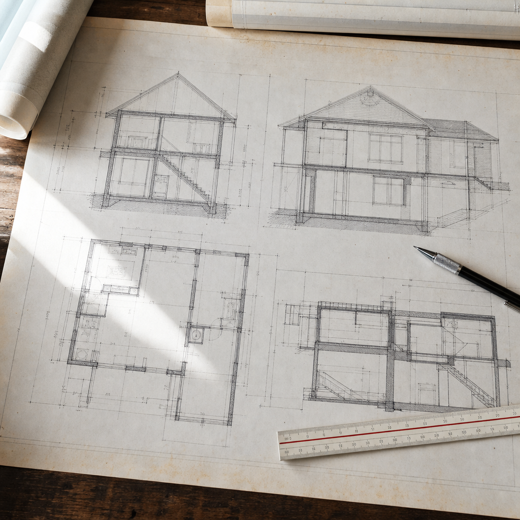
Minimum ceiling heights for habitable spaces, basements, and circulation pathways in Alberta homes are enforced under the National Building Code - 2023 Alberta Edition (NBC(AE)). Section 9.5.3.1. and related code provisions dictate the explicit clearances, with direct implications for floor plan dimensioning, detail development, and construction verification. Accurate, concise, and unambiguous documentation minimizes plan-review redlines and prevents costly site rework.
Ceiling Heights for Habitable Spaces: Plan Sheet Dimensioning under NBC(AE) 9.5.3.1.
Minimum Requirements: Code-Mandated Heights by Room Type
Section 9.5.3.1. of the NBC(AE) prescribes the minimum ceiling heights for various room types and building areas in residential occupancies. The following table, derived directly from the Alberta Building Code, establishes the minimum thresholds:
- Living rooms, dining rooms, kitchens, bedrooms (including master): 2.1m minimum over the lesser of the area of the room or (living: 10.0 m², dining: 5.2 m², kitchen: 3.2 m², master bedroom: 4.9 m², other bedroom: 3.5 m²).
- Other habitable rooms: 2.1m over the lesser of the area of the space or 2.2m².
- Bathrooms, water-closet rooms, above-grade laundry areas: 2.1m over the lesser of the area or 2.2m².
- Passages, halls, and main entrance vestibules: 2.1m over entire area.
- Unfinished basements (including basement laundry): 2.0m clear under beams and in any location normally used for passage.
Section 9.5.3.1.(3) further mandates that “the area of the space shall be measured at floor level.” Hidden areas above stairs, storage closets, or inaccessible corners do not contribute to the required clear-height area.
Drafting Conventions: Communication on Plan Sheets
- Room Labels: All floor plans must include unambiguous, code-specific room labels (e.g. “BEDROOM 2 (MIN. CLG 2.1m)”). Ambivalent tags like “flex space” or “bonus area” risk rejection at plan review, with redlines requesting explicit use classification.
- Dimensioning: Each habitable room should have a clear vertical dimension line in section, explicitly stating F.F. (Finished Floor) to F.C. (Finished Ceiling). E.g. “F.F. TO F.C. = 2100mm MIN.”. If there are dropped ceilings or bulkheads, add a matchline or bubble note marking the precise extent of high/low zones.
- General Notes: On the General Notes or Interior Schedules sheet, include: “ALL CEILING HEIGHTS NOTED ARE FINISHED FLOOR TO FINISHED CEILING AND SHALL BE VERIFIED TO COMPLY WITH ABC 9.5.3.1., UNLESS SPECIFICALLY NOTED OTHERWISE.”
- Section and Detail Markers: Section cuts through any area with a ceiling height transition-particularly kitchens, master bedroom suites, basement rec-rooms, and stairways-should be flagged and referenced to a detail showing the minimum height and extent per code.
Room-by-Room Detailing: Common Pitfalls and Plan-Review Traps
- “Insufficient clear height at kitchen bulkhead adjacent to HVAC chase.” Common plan-review comment arising when plan only shows the main ceiling plane; verify transitions and call out all soffits/bulkheads with their AFF (Above Finished Floor) height.
- Inadequate dimensioning on floor plans for secondary bedrooms: Reviewers may request redline, “Provide dimension from finished basement slab to underside of finished ceiling per bedroom area-Not shown.” Always provide these dims, not just for the primary living area.
- Ambiguity in area qualification: “Show area complying with min. ceiling height-Does not appear continuous with room entry” is a typical redline in plans where dropped ceilings form a “tunnel” disconnected from the entry (non-compliant).
STANDATA and Secondary Suites: Local Provisions
STANDATA bulletin 23-BCB-007 clarifies that houses with secondary suites have no relaxation of minimum ceiling height requirements; NBC(AE) minimums apply throughout. The only provision for lower heights is over stairs for suites (see Section 9.8.2.2., covered later).
Drawing Note Example: Compliance Reference
“ALL HABITABLE ROOMS TO PROVIDE MINIMUM CEILING HEIGHTS AS FOLLOWS (AS PER ABC 9.5.3.1.): LIV/DIN/KIT/BED/HALL: 2.1m; UNFINISHED BASEMENT: 2.0m; SEE SECTIONS FOR EXTENT AND DETAILS.”
Obstructions, Bulkheads, and Dropped Ceilings: Detailing Reduced Ceiling Areas under ABC(AE) 9.5.3.2.
Code Scope: Bulkhead Permissibility and Minimums
Section 9.5.3.1. and 9.5.3.2. discuss allowable ceiling reductions due to beams, ductwork, or architectural bulkheads. In all cases, any such dropped portion may not reduce the clear height in required minimum area below the limit for that space: usually 2.1m for habitable rooms, 2.0m for basement passages. In practice, this means mechanical and structural elements must be routed (or encased) so as not to intrude into required contiguous high-clearance zones.
- Bulkheads & Mechanicals: Duct and pipe chases should be coordinated during schematic design. When bulkheads are unavoidable in a kitchen, bath, or hall, their width, length, and AFF height must be dimensioned and graphically hatched/called out on both plan and reflected ceiling plan.
- Sectional Clarity: Section details-at 1:20 or 1:10 scale-should cut perpendicular to the bulkhead, dimensioning finished floor to lowest finished face of the bulkhead, e.g. “BULKHEAD: 2050 mm AFF. WIDTH = 430 mm. GYP BD ON 2x4 FRAMING AS SHOWN.”
Drawing Conventions: What Disciplines Require
- Plan Sheet Call-Outs: All bulkheads must be annotated with a boxed tag or bubble: “MIN. CLG. HGT. 2.10m” or “BULKHEAD 2050mm AFF” (Above Finished Floor). Use heavy dashed line for extent of soffit/bulkhead on floor plan and ceiling plan.
- Sectional Elevations: Align with mechanical overlays; show beams, pipes, ducts in position relative to finished ceiling. “BULKHEAD DROPS 300mm FROM MAIN CEILING PLANE FOR 600mm WIDTH OVER LAUNDRY.”
- Enlarged Details: In critical runs-e.g., where plumbing stacks cannot be rerouted, or major HVAC crossovers occur in hallways-provide enlarged “mechanical ceiling zone” detail keyed off main plan/section.
Mechanical Trade Coordination
Late-stage plan-review frustration commonly arises when the architectural plans show finished ceilings at 2.1m, but mechanical, plumbing, or structural installs on the RFI set necessitate a dropped ceiling below code minimum in a habitable zone. Early cross-discipline coordination is mandatory. Key notes include:
- “MECHANICAL AND STRUCTURAL TRADES TO COORDINATE ALL CONCEALED RUNS TO MAINTAIN MIN. CEILING HEIGHTS AS SHOWN. NOTIFY DESIGNER IMMEDIATELY IF PROPOSED RUN INTRUDES INTO REQUIRED CODE MINIMUM CLEARANCES.”
- Indicate all access panels and code-required clearances for service ducts-e.g. “Provide 300x300mm access panel for shut-off at laundry bulkhead.” Be explicit on drawing and mechanical schedule.
Common Pitfalls: Bathrooms, Corridors, and Plan Reviewer Notes
- “Bulkhead intrudes into required passage area-Revise layout or raise bulkhead to maintain 2.1 m min.” Typical comment for narrow hallways with oversized HVAC chases.
- Bathroom bulkheads over vanities-a common error is neglecting to dimension these explicitly, resulting in as-built encroachment into the code-required clear area (2.1m over 2.2m²). Always draw ceiling outline and dimension over measured “minimum area.”
- Living room coffered ceilings: when detailing coffer drops, include section and plan dimensions. If the “coffer” drops below min. height, ensure high portion complies over required area.
Example Notation and Detail Tags
- “SEE DETAIL 2/A5.1 FOR BULKHEAD OVER HALLWAY - PROVIDE 2100mm AFF MIN. OVER FULL PASSAGE WIDTH”
- “DASHED LINE INDICATES AREA OF CEILING BELOW 2.1m - NOT TO ENCROACH ON CODE-REQUIRED CLEAR AREA”
Basements: Achieving and Detailing Code-Compliance Below Grade
Minimum Heights and Finished Floor Implications
For basement spaces, code requirements are particularly sensitive to finished floor elevations, structural constraints, and mechanical routing. Per Section 9.5.3.1.:
- Unfinished basements, including laundry: 2.0m minimum under beams and all areas normally used for passage.
- Finished basement habitable rooms: 2.1m minimum, with the same minimum-area criteria as above-grade rooms.
Detailing from Slab Up: Dimensions and Floor Build-up
- All dimensions must be from finished basement slab or subfloor to finished ceiling plane, taking into account all floor build-ups: radiant panel assemblies, insulation, subfloor panels (e.g., DRIcore), and final finishes (e.g., laminate, LVT, carpeted pad).
- On both plan and section, provide: “FINISHED SLAB TO FINISHED CEILING = 2100 mm (SEE FLOOR SCHEDULE FOR BUILD-UP DETAILS)”. Schedule or keynotes to describe all materials and thicknesses contributing to slab buildup.
- Dimension heights under all major beams and at every bulkhead/mechanical drop (especially HVAC runs over bedroom entries or rec-rooms). E.g., if structural beam drops to 2.05m and HVAC duct hangs another 100mm below, the combined clearance may drop under 2.0m, necessitating design revision.
Addressing Renovation and Existing Foundations
- For “as-built” basements, site verification is critical. Construction sets must annotate: “ALL EXISTING BASEMENT FLOOR-TO-CEILING HEIGHTS TO BE FIELD-VERIFIED PRIOR TO FRAMING FINISHES. DESIGNER TO BE NOTIFIED OF ANY LOCATIONS BELOW 1950mm (HABITABLE) OR 2000mm (UNFINISHED/PASSAGE).”
- Underpinning or benching: If slab lowering is required, detail this on the demo/new construction plan and include relevant cross sections showing step-downs and new footing details.
Mechanical Services and Coordination Notes
- For mechanical systems, especially forced-air basements, denote on M-plan or composite overlay: “ALL DUCTWORK TO MAINTAIN 2100mm AFF (FINISHED) IN HABITABLE AREAS AND 2000mm AFF IN PASSAGE AREAS.”
- Indicate the exact path and size of HVAC trunk lines, especially where they must cross rec-room or bedroom ceilings. “No mechanical drops below 2.10m in primary rec-room area” should be flagged on both architectural and mechanical sets.
Plan-Review Comments and Typical Redlines
- “Confirm min. 1.95m (ABC Sec.9.5.3.1.) clear height in finished basement bedroom after flooring-Drawings do not show finished build-up.”
- “Ductwork in plan projects bulkhead below code minimum-revise or reroute.”
- Burst dimensions and as-built datums: Include explicit reference on plan for slab elevation and call for field verification beyond design assumptions.
Annotations for Field Verification and Site Instructions
- “INSTALLATION OF ALL SUSPENDED AND FINISHED CEILING SYSTEMS IN BASEMENT TO MAINTAIN MIN. CODE HEIGHTS. CONTRACTOR TO NOTIFY DESIGNER OF ANY FIELD CONDITIONS IMPACTING CLEARANCES.”
- In plans with variable slab elevations (stepped footings, sloping sites): use spot elevations and provide a floor slope/height map as an overlay or schedule.
Stairways and Ramps: Headroom Clearances under NBC(AE) 9.8.7.1.
Headroom Over Stairs: Exact Requirements
Section 9.8.7.1. of the NBC(AE) and its related subsections delineate minimum headroom over stairways and ramps as follows:
- General stairways/ramps: 2,050mm (6 ft 9 in) vertical clearance measured from a line tangent to the tread nosings or ramp surface vertically to the lowest overhead obstruction.
- Single dwelling units and secondary suites: Reduced to 1,950mm (6 ft 5 in).
- Stairways under beams/ducts (secondary suites only): Minimum 1,850mm (6 ft 1 in) permitted.
These reduced minimums may not be applied piecemeal within a single stair run-if the run serves both a principal and a suite area, the higher requirement prevails for the continuous path.
Sectional Detailing: Drawing the ‘Vertical Projection’
- Referencing Treads: Headroom is measured perpendicular from a line connecting the nosings of all treads along the stair run.
- Section Cuts: Building section cuts must be placed through the stair’s worst-case point of possible encroachment (e.g., under a landing or sloped ceiling). The headroom plane should be a bold dashed reference line-call out with a box: “MIN. HEADROOM CLG. 2050mm SEE 9.8.7.1.”
- Obstructions: Drop beams, mechanical chases, and structural soffits above stairs must be dimensioned in both section and plan. If the soffit does not encroach into the stair’s “vertical projection,” indicate with notation: “NO OBSTRUCTION WITHIN MIN. HEADROOM ZONE”.
Plan & Elevation Drawing Strategies
- Enlarged Details: Where stair headroom is marginal, include enlarged details showing the relationship of stair stringer, treads, and overhead element, with all finishes called out (e.g., “2x10 stringer, 13mm GWB, 19mm hardwood tread”).
- Critical Points: Always flag the upper- and lower-most treads, and landings, particularly where the ceiling above slopes downward, or a landing is offset beneath a beam. Plan reviewers often mark: “Verify headroom to lowest ceiling point at landing and along all treads between floors.”
- Dashed Overhead Lines: On plan, any feature more than 1200mm above the floor should be shown dashed. Stair sections to include the outline of bulkheads or sloped ceilings for direct measurement.
- Detail Key-Ins: For unique stair conditions (e.g., split-levels, dogleg stairs under sloped roofs), use bullet notes and key plans-“SEE DETAIL 7/A4.3 - STAIR HEADROOM AT SLOPING CEILING RETURN.”
Redlines and Site Issues
- “Provide section showing clear dimension from tread nosings to underside of bulkhead at lower landing-not provided.”
- At site, common field RFI: “Ductwork interferes with stair headroom-detail revision and possible reroute required.”
- Best practice: At permit and construction sets, annotate: “VERIFY HEADROOM OVER STAIRWAY ONSITE PRIOR TO ROUGH-IN OF MECHANICAL AND FRAMINGBULKHEADS.”
Related Dimensions and Guards
- In conjunction with 9.8.7.1., ensure all stair and ramp guards meet code for opening size, graspability and height (1067mm above landing, 865mm above tread nosing, see 9.8.8.2.).
- Dimension risers (maximum 200mm residential) and treads (minimum 255mm residential) per 9.8.4.1.
Plan Review Redlines, Jobsite Call-Outs, and Critical Verification Procedures
What Plan Reviewers and Inspectors Actually Write
- “Verify minimum ceiling height in basement bedroom with flooring finish.” If plans omit finished floor detail under carpet or laminate, this comment always appears.
- “Bulkhead under main duct reduces hallway height-enlarge plan and provide AFF dimension at most restricted point.”
- “Stair headroom not dimensioned-revise section. RFI may be required.”
- On as-builts: “Field verify all finished heights prior to drywall. Notify architect of any discrepancies.”
Sheet Conventions: Notes and Benchmarks
- Datum Reference: Every planset should establish a primary finished floor datum, e.g. “F.F. 0.000 = MAIN FLOOR FINISHED ELEV.” and “B.S. 0.000 = BASEMENT SLAB FINISHED ELEV.” All dimensions for ceiling heights, stair rise, and mechanical zone clearances to reference this point, not just arbitrary local dimensions.
- Critical Jobsite Call-Outs: Use large, bold notes: “CONTRACTOR TO FIELD VERIFY ALL FINISHED CEILING HEIGHTS PRIOR TO FRAMING CEILINGS. REPORT ANY AREAS OF NON-COMPLIANCE TO DESIGNER FOR DIRECTION. ALL REPAIRS/ADJUSTMENTS TO BE AT CONTRACTOR’S EXPENSE IF INSTALLED BELOW CODE.”
- Verification Points: Identify all rooms with critical minimum ceiling height (e.g., “BEDROOM 3 MIN. CLG. HGT. 2.1m - CRITICAL VERIFICATION POINT”). Schedules or plan annotations can list these.
- Spot Elevations and Level Lines: On section drawings, mark spot elevations for existing floor surfaces, joists, finished ceilings, lowest point of ductwork for field check (“LOWEST CEILING BULKHEAD = 2005mm AFF AT HVAC CROSSOVER - FIELD VERIFY”).
Procedures for Avoiding Field Issues & Delays
- Include explicit finish schedules: flooring, drywall, subfloor systems, tile buildup-account for every mm contributing to floor-to-ceiling dimension.
- Pre-construction “high-risk” walk-through: perform with mechanical and framing trades, especially for infill/reno situations with tight headroom. Attach pre-drywall inspection sign-off sheets to plan sets for field documentation archive.
- Clarify process for reporting and resolution: “ANY FIELD-DETECTED DEFICIENCIES BELOW MINIMUM CLEARANCE TO BE REPORTED TO DESIGNER AND INSPECTOR BEFORE CEILING CLOSURE. DO NOT DRYWALL NON-COMPLIANT CEILINGS WITHOUT WRITTEN INSTRUCTION.”
Material and Assembly Specifications to Support Compliance
- Gypsum Board: 13mm standard for ceilings. Where sound attenuation required, note assembly type and thickness accordingly in specifications. “GWB/13 ON 2x4/@ 400mm O.C. WITH R22 INSL.” is a typical callout.
- Resilient Channel: When used for acoustics, detail the drop-“Resilient channel (RC-1) to drop ceiling 19mm, maintain minimum code ceiling height with channel assembly.”
- Flooring: detail finish type and exact thickness (e.g., 12mm LVP vs. 30mm carpet + underlayment) on finish schedule.
- Fire-rated assemblies: If required (multi-family, suites): note ULC or cUL assembly reference on section detail and provide total assembly height in dim chain.
Conclusion: Coordinated Code-Compliant Ceiling Heights in Alberta Home Drafting
Precise documentation of minimum ceiling heights-rooted in explicit code clauses, strategic plan and section callouts, and enforceable jobsite notes-is fundamental to smooth permit approvals and inspection sign-offs in Alberta residential construction. Dimension every ceiling, bulkhead, and stair headroom with cross-referenced details and clear annotations. Foresee site-verified discrepancies through diligent coordination of structure, mechanicals, and finishes, always referencing Section 9.5.3.1 and related NBC(AE) provisions. Annotate finished floor datums, call for pre-framing verifications, and ensure all code-required clearances survive the complexity of real-world construction. This disciplined approach from drafting table to jobsite establishes Kingsway Drafting & Design as a leader in Alberta code-compliant residential home design.