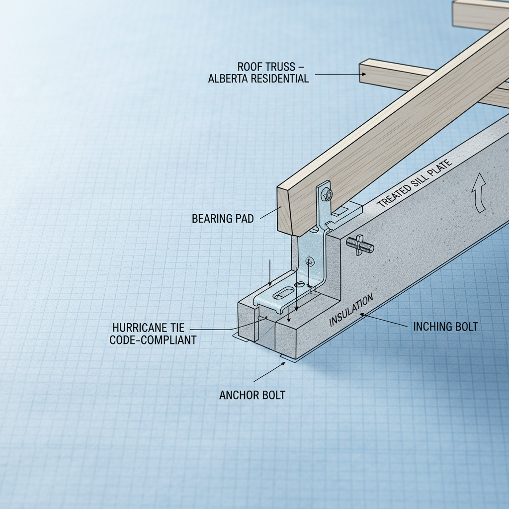
End bearing length, connection detailing, and protection from environmental effects are pivotal in drafting code-compliant roof truss assemblies in Alberta. Every calculation, fastener specification, and line drawn on a plan directly contributes to the structural resilience demanded by the National Building Code - 2023 Alberta Edition (NBC(AE)). Close scrutiny of every bearing interface and connection across a wide range of climate and loading conditions ensures homes can resist snow, wind, and time itself.
Roof Truss Bearing Details: Where Loads Meet the Structure
A roof truss’s functional integrity starts with how it connects to the structure below. The transmission of roof loads-dead, live, wind, snow, and seismic-relies on precise support and protection at each bearing point. Code stipulations define clear, actionable requirements and are further shaped in practice by field realities, truss manufacturer instructions, and evolving municipal standards.
Minimum End Bearing Length: Beyond Just Numbers
Article 9.23.14.3 of the NBC(AE) stipulates at least 38 mm of required end bearing length for roof trusses. In drafting practice, this dimension governs the way wall plates, beams, and truss shoe details are configured. Importantly, trusses may sometimes bear on narrow wall plates, engineered beams, or on custom framing details for vaulted or complex roof designs.
For common residential construction, the most frequent configuration involves a double top plate (typically 38 mm x 184 mm) supporting prefabricated trusses. The drafting must clearly annotate bearing length and call out the dimension on both plan and section drawings to guide onsite placement. A bearing length less than 38 mm concentrates considerable loads onto a reduced wood area, risking local crushing or splitting. Drafters should always be conscious of cumulative load cases, especially at girder trusses or hip ends, which may bring much higher point loads to localized bearing points.
- Bearing on Beams: If a truss lands on an engineered beam or a lintel (such as over large window or sliding doors), the plate and beam arrangement needs close attention. Drafters commonly specify a bearing block or supplementary stud beneath the point of bearing, annotated in both section and schedule to ensure proper transfer of loads.
- Bearing at Complex Junctures: Truss intersections-such as valleys, off-angles, or at gable returns-require dimensioning of custom bearing blocks. If the bearing width is reduced due to architectural features, the drafter should indicate an engineered bearing pad or order a supplementary design from the truss engineer.
Explicit detailing of all bearing lines reduces framing errors in the field. The drafter acts as the front-line defender against hidden shortcuts that could introduce non-compliance or latent hazards. Bear in mind that municipal building inspectors frequently red-flag ambiguous bearing callouts on plans.
Notching and Drilling Restrictions: Keeping Members Intact
Maintaining the load-carrying capacity of roof structural members is non-negotiable. Articles 9.23.5.1 and 9.23.5.2 of the NBC(AE) prescribe precise, quantitative limits on notching and drilling:
- Notching: Only permitted at the member’s top, within half the joist depth from the bearing edge, and limited to a cut no deeper than one-third the member’s depth. This is rarely an issue for manufactured trusses, since notching is typically prohibited by truss manufacturers' instructions, but can impact site-built roof framing and accessory blocking.
- Drilling: Holes may not exceed one-quarter the depth of the member, and must have at least 50 mm clearance from both the top and bottom edges. Like notching, drilling through truss chords or webs is generally forbidden unless specifically approved by the truss engineer.
From a drafter’s perspective, notation is key. All plan sets must explicitly state that no on-site notching or boring of manufactured components is permitted. Details should define allowable modifications for non-load-bearing blocking or decking supports only. Truss shop drawings (engineer-sealed) always take precedence, and their no-modification instructions must be reflected in notes or details on the architectural set.
Drilling for mechanical, plumbing or electrical chases is a perennial source of on-site conflict. Drafters can proactively reserve chase spaces above ceilings or coordinate with MEP consultants to minimize destructive “field solutions,” which frequently violate code-and can cripple structural capacity. Where a hole or notch is essential to the design, the drafting set should call for “engineered review” or “coordinate with structural.”
Protection from Decay and Dampness: Preserving Capacity for the Long Haul
Alberta’s unique climate, with freeze-thaw cycles and periods of high moisture, makes protection of wood framing from decay especially critical. Article 9.23.2.2 mandates that roof truss ends embedded in masonry or concrete be protected either by a suitable preservative or by providing a 12 mm air space for ventilation.
- Embedded Truss Ends: Situations arise in certain low-pitch roofs-such as at the interface with a masonry party wall or at basement walkout entries-where truss ends bear into a concrete or block wall. The drafter must annotate both preservation treatment requirements and the detailing of air gaps. This often includes specifying “PT” (pressure treated) lumber, explicit notes on air space shims, and the use of drip caps or sheet flashing if above grade.
- Separation from Concrete: Where untreated (non-PT) wood is supported directly on concrete and in contact with earth or fill, Article 9.23.2.3 requires a 0.05 mm polyethylene or a layer of Type S roll roofing as a capillary break. Every drafter should detail this separation in all foundation and floor-to-wall details-commonly as a “SLP: 0.05mm poly separation” callout below sill plates or any framing at rim joists in contact with the foundation wall.
Failure to provide these details at the drafting stage can lead to the slow, silent failure of structural members via rot and decay-often undetected until expensive (and invasive) repair is required. Field review will frequently reveal missing barriers or untreated wood in high-risk zones; precise annotation and prioritized details prevent these issues from arising.
Truss Tie-Down Details: Resisting the Forces of the Prairie Climate
Alberta’s combination of strong prairie winds, variable snow loads, and increasingly severe storms makes tie-down and anchorage details a mission-critical area for drafters. Every roof truss connection delivers not only gravity and snow loads, but also must resist substantial uplift and lateral loads, especially in exposed subdivisions or rural locations.
Foundation and Frame Anchorage: Setting the Load Path
The structural shell starts with robust anchorage at the base. Article 9.23.6.1 mandates that the sills (where the wall system meets the foundation) be secured with anchor bolts-minimum 12.7 mm diameter, spaced at 2.4 m maximum, and embedded at least 100 mm into the concrete or masonry. In practice:
- Scheduling Anchor Bolts: Drafters must show anchor bolts at every significant wall segment, and call them out in all typical wall sections. Locations for anchor bolts around door and window openings should be highlighted, as missing bolts at these weak points can expose the structure to racking in strong winds.
- Upgrading for Severe Conditions: For zones with extreme exposure or where overhangs increase uplift risk, drafters may recommend tighter anchor bolt spacing in their general notes, or specify “per structural” to defer to case-by-case engineering judgment.
- Compatibility with Existing Structures: In additions or renovations, connection details must coordinate with the original assembly. For example, retrofitted anchor bolts may require epoxied rods or alternative hardware, which should be clearly detailed for approval.
These fundamental anchorages set the stage for a continuous load path all the way from the roof through the structure to the foundation.
Truss-to-Wall Plate Connection: The Critical Interface
The link from truss to wall plate is the frontline defense against wind uplift. NBC(AE) 9.23.3.4 stipulates three 82 mm nails, driven in toe-nailed fashion, to secure each truss to the plate. This demands careful documentation:
- Truss Layouts: Every plan set, and each truss layout sheet, should annotate nail quantity, size, and nailing angle so that site workers can clearly identify the requirement. “Three 3-1/4” spiral nails per truss seat” can be called out with an arrow at every truss location along the plate.
- Wall Plate Coordination: The drafter must verify that double top plate assemblies are continuous and appropriately lapped at wall breaks/returns, per 9.23.13, allowing nail fasteners to be fully effective. Inconsistency in plate continuity may allow trusses to “walk” under load.
- Site-Made Trusses and Rafters: Where nail-plate trusses are site-built or where trusses meet hip or valley beams, drafter notes should make clear any special nailing or supplemental strapping requirements, referencing truss manufacturer specs or structural review as needed.
In high-wind areas, simple nailing is not enough. The code (9.23.3.4(3)) requires positive mechanical tie-down with metal connectors when wind pressure equals or exceeds 0.8 kPa-conditions not uncommon in southern and central Alberta.
Wind Uplift Resistance and Mechanical Tie-Downs: Galvanized Straps and Connectors
For resisting wind uplift at the truss-seat-to-wall-plate connection, the NBC(AE) defines both material and fastener specifications:
- Straps: 50 mm wide galvanized steel, minimum 0.91 mm thick.
- Fasteners: A minimum of four 63 mm nails at each end.
- Factored Load: Connection must resist 3 kN of uplift.
These details are critical where houses are located in open landscapes (rural acreages), new subdivisions without mature windbreaks, or hilltop sites. Drafters must go beyond simply noting “install hurricane ties”-details should show:
- Strap type and manufacturer (where specified), orientation, and whether the connector is installed on the inside or outside face of the wall.
- Fastener type and nailing pattern both into the truss and into the top plate (pre-drilling if specified by strap manufacturer).
- Whether straps overlap double top plates or are attached individually to each plate.
- Clear notes about cumulative uplift for girder or valley trusses, where standard ties may need to be supplemented by engineered connectors.
- Instructions to coordinate with truss manufacturer’s uplift tables, which may supersede code minimums.
Failing to apply the right tie-down method in the field can lead to catastrophic truss failures under suction or negative pressure from Chinook winds. Drafters’ details are the first-and sometimes only-reference available for site carpenters or framing crews under time pressure.
Continuous Tie-Down Systems: Creating an Unbroken Load Path
In high-exposure or engineered builds, a continuous tie-down system-not merely local strapping or clip fixes-is increasingly common. These systems ensure roof uplift and racking forces travel continuously from roof framing, through wall assemblies, all the way to footings. The approach includes:
- Anchored Straps or Tension Rods: Specified in section details, often running beside stud packs at principal load points or girder truss locations.
- Compatible Hardware: Drafters must ensure specified connectors are compatible with underlying framing systems (engineered lumber vs. SPF, for example), and reference both manufacturer load tables and code minimums.
- Through-Wall Detailing: While most single-family builds in Alberta use isolated tie-downs at major points, drafters should be explicit-“continuous metal tie from truss seat to anchor rod at foundation, per manufacturer,” and include a cross-sectional detail.
Homes subject to structural engineering (due to wind exposure category, irregular massing, or attachment points for solar or HVAC equipment) demand that design drafters schedule every connector on the plans for building inspector signoff. Attention to detail here not only optimizes structure but also supports easier permit review and smoother handover to site framing crews.
Engineering Requirements and Verification: Professional Expertise and Documentation
Professional Authentication in Alberta Municipalities
Evolving municipal policy recognizes both the sophistication of modern residential truss systems and the risks of uncoordinated installation. By March 2026, Edmonton will require roof truss assemblies to be authenticated by an Alberta-licensed engineering professional for all new single-family homes, semi-detached homes, and rowhouses up to four units. (City of Edmonton Policy Bulletin B23-03)
Authenticating the truss package includes:
- Review of full architectural and roof plans for accurate truss layout.
- Check of engineered shop drawings for conformance to both NBC(AE) and TPIC (Truss Plate Institute of Canada) 2019 standards.
- Authentication stamp explicitly referenced in submission package, acting as a control against unauthorized design modifications on site.
- Alignment with Alberta Municipal Affairs STANDATA 23-BCI-015R1, providing province-wide clarity around roles, responsibilities, and submission content.
For architectural drafters, this means maintaining close collaborative workflows with truss manufacturers and their engineers. During drafting, all required authentication, drawing references, and coordination points should be proactively called out in the general notes and schedules. Changes to plan geometry, layout, or load paths mid-cycle must prompt immediate notification to truss engineers and an updated set of authenticated documents pre-approval.
Compliance with TPIC 2019 and Recognized Standards
The NBC(AE) sets the Truss Plate Institute of Canada’s 2019 standard-“Truss Design Procedures and Specifications for Light Metal Plate Connected Wood Trusses”-as the technical authority for truss design and fabrication.
- Manufacturing Compliance: Architectural plans should reference “truss design and fabrication per TPIC 2019” wherever roof trusses are indicated, to ensure downstream engineering and manufacturing use the correct basis of design.
- Quality Assurance: Drafters should require as-built truss documentation (“truss layout and shop drawing package to be provided for review, per TPIC 2019, prior to installation”) in project documentation for permit and inspection records.
- Specialty Hardware: Where truss-to-wall or continuous tie-downs employ proprietary hardware, it must be certified as TPIC-compatible. Illustrations on the details sheet may help clarify unusual or engineered connections for site and inspector comprehension.
Many failure claims can be traced to unauthorized modifications or a mismatch between truss design, site conditions, and actual loads. By anchoring all drafting and review to the explicit baseline of TPIC 2019, drafters protect the structure, streamline the permit process, and reinforce compliance from start to finish.
Practical Considerations: From Drawing Board to Construction Site
Coordination with Truss Manufacturers
Successful roof framing execution relies on early and continuous coordination between the design drafter, the truss engineer, and the fabricator. Design intent, dimensional accuracy, and realistic installation sequencing all need to be communicated with clarity from the earliest plan iteration. Practical drafter actions include:
- Dimensioning for Manufacture: Clean, unambiguous truss layout plans-defining bearing lines, overhangs, roof angles, and valleys-ensure the truss manufacturer’s shop drawings are precise and referenceable. Lack of clarity translates to costly delays or on-site workaround changes that may not comply with code mandates.
- Identifying Critical Points: Girders, cantilevers, valleys, and girder truss supports must be flagged with callouts referencing “coordinate support with truss mfr/eng.” Complex multi-level roofs or attic truss systems may require schematic 3D isometrics for clarity.
- Construction Sequencing: For infill and tight-lot builds, drafters should anticipate limited maneuvering room for truss placement-and detail any temporary tie-downs, bracing, or installation accommodations based on discussion with the manufacturer and builder.
Missed opportunities for up-front coordination translate to on-site confusion, which can spiral quickly into noncompliance if field fixes depart from engineered truss specifications. Precision in plan notation saves time, money, and avoids code compliance setbacks.
Site Verification and Quality Assurance
Even the most well-detailed plan requires real-world verification. Drafter-prepared site checklists and explicit layout sheets play a vital role in guiding framers and inspectors through quality control:
- Field Inspections: Municipal inspectors and consulting engineers will typically check truss bearing lengths, connector types, fastener counts, and anchor bolt locations in the field against the plan.
- Critical Details: Details for truss seat tie-downs, bearing pads at girder trusses, minor notching allowances, and anchor hardware should be included on all framing detail sheets, with references back to code articles and truss engineer drawings as needed. This “trail of authorization” helps both inspectors and site supervisors enforce correct installation.
- Pre-Installation Meeting: Hosting design coordination meetings prior to truss delivery can clarify plan intent, fastener requirements, and compliance notes for contractors-a powerful tool for reducing uncertainty and pushback in the field.
Documentation and Record-Keeping: The Foundation of Defensible Compliance
Pervasive throughout every step of code-compliant drafting, documentation provides the legal and practical evidence of code adherence. In Alberta’s regulated environment, documentation serves multiple essential purposes:
- Permitting and Inspection: Full drawing sets, authenticated engineer drawings, and truss manufacturer packages must be retained from permit submission through to final occupancy, and kept on site for spot inspection.
- Change Control: Any post-approval change in roof geometry, truss layout, or tie-down specification requires a documented revision with updated authentication from the truss engineer. Notes in the drawing register and revision clouds make these changes traceable and audit-friendly.
- Future Renovation Support: Accurate records (as-built truss layouts, tie-down and bearing details, list of installed hardware) assist architects, builders, or homeowners contemplating future modifications, preventing accidental compromise of structural safety.
- Warranty and Litigation Defense: Should performance or settlement issues arise post-occupancy, plans and supporting documents provide proof of code-compliant original construction-a critical shield against warranty claims or legal action.
Drafters support long-term building resilience not only with careful drawing, but through a culture of meticulous paperwork and anticipation of all approval, inspection, and maintenance needs.
Expert Insight: Drafting Strategies for Alberta’s Structural Reality
Anticipating Prairie Wind and Snow
Alberta homes face exceptional environmental loads, with expansive open exposures, unpredictable wind patterns, and winter snows that can overwhelm under-designed structures. Effective roof truss drafting embraces these realities by:
- Consulting Climate Data: Knowing the regional wind and snow load zones sourced from NBC(AE) mapping allows drafters to proactively specify hardware (straps, fasteners, bracing) and to signal when engineered uplift tables must be referenced.
- Slope and Overhang Coordination: Drafters stock roof plans with annotations alerting the truss engineer to “overhangs exceeding 600 mm” or “slopes below 3/12,” both of which trigger heightened load transfer and bearing detail attention.
- Edge Condition Mastery: Where roofs interface with parapets, party walls, or change slope/height abruptly (as in many infill designs), section details must cover transitions in both bearing and tie-down-these are common failure points, particularly in urban and rowhouse applications.
Balancing Buildability and Code
Unbuildable code compliance is functionally equivalent to noncompliance. Drafters must ensure even the most demanding plan details are actually feasible in the field, by:
- Dimensioning for Framer Access: All tie-down and bearing details must reflect actual clearances and available access on site. For instance, tie-down straps should be located where they can be properly nailed and inspected, rather than buried inside dense blocking runs or obstructed attic spaces.
- Sequencing for Real-World Construction: Section sheets can note proper sequencing: “anchor truss seat tie-downs to plate prior to sheathing installation,” preventing missed connections obscured by later work.
- Standardization of Details: Whenever possible, drafters should standardize details so that site teams can perform repetitive, code-compliant work across the building-even minor changes to strap type or nailing pattern must be highlighted with bold text or callouts to avoid misapplication.
Communicating with Stakeholders: The Drafter as Translator
The drafter’s annotated detail sheet is the lingua franca between engineers, manufacturers, site framers, inspectors, and ultimately the future home occupants. Effective drafter practice involves:
- Clear, Layered Detail Sheets: All bearing and tie-down details should be clustered at a single location in the drawing set, with cross-references to code articles and notes for “see truss engineer’s shop drawings.”
- Note Hierarchies: General notes on plans should point to “critical tie-downs per detail X/X and truss engineering,” giving quick access for inspectors and minimizing reinterpretation in the field.
- Adaptation to Builder and Site Experience: Where custom or proprietary hardware is specified, details can include installation instructions or manufacturer pictograms to support less experienced installers.
Conclusion: Drafting for Strength, Safety, and Permit Success
Ensuring code-compliant roof truss bearing and tie-down details in Alberta is a multidisciplinary, detail-driven process built on a foundation of numerical precision, environmental awareness, engineering oversight, and proactive communication. Connecting abstract code requirements directly to buildable, clear, and fully-documented details empowers all project stakeholders to safeguard the structure, pass inspection, and ensure comfort and safety for years to come.
Always, precise dimensions, fastening schedules, and detailed notes-rooted in NBC(AE) requirements and recognized standards like TPIC 2019-translate to more confident, durable, and inspectable residential builds across the province. Every drafter’s plan is a living document, evolving with code cycles, engineering standards, and the practical lessons of builders and inspectors across Alberta’s diverse climate and construction landscape.
For Alberta projects requiring meticulous, code-aligned drafting of roof truss systems, Kingsway Drafting & Design is committed to clarity, compliance, and superior service.