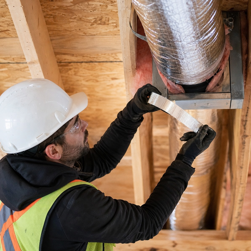
Exhaust fan ducting traversing unheated spaces in Alberta residential construction is subject to detailed technical requirements spanning thermal insulation, airtightness, vapour control, fire protection, termination, and the prevention of condensation and air leakage. The National Building Code of Canada (NBC) 2023 Alberta Edition, in effect October 16, 2026, sets precise standards that appear repeatedly in plan set notes, section detailing, material schedules, and on redlined plan reviews. Proper construction drawings, code call-outs, and onsite coordination are essential to ensure compliance, energy efficiency, and building durability.
Alberta Building Code Part 9 Requirements for Exhaust Duct Insulation and Sealing: Code References, Drawing Notations, and Plan Compliance
ABC (2023 Alberta Edition) Section References and Plan-Set Notation
Exhaust duct insulation and airtightness requirements for Alberta homes are dictated chiefly by ABC Div. B Sections 9.32.3.1, 9.32.3.2, 9.36.2.11, and 9.36.2.12. Provisions specifically reference mechanical ventilation, installation quality, building envelope airtightness at penetrations, and air barrier system continuity:
- Section 9.32.3.1: All houses with electrical power must include a mechanical ventilation system (e.g., exhaust fans) to CAN/CSA-F326-M or as per this subsection.
- Section 9.32.3.2: Mandates mechanical ventilation design and installation follow "good practice," referencing the ASHRAE Handbook and HRAI Digest.
- Section 9.32.3.11 (3): Explicitly requires that exhaust ducts passing through unheated spaces must be insulated to not less than RSI 0.5 (R-2.85), typically realized as a minimum 25 mm (1") fiberglass or equivalent.
- Section 9.32.3.11 (8): Requires all joints in the ventilation duct system be "airtight," sealed with mastic, metal foil tape, or manufacturer-approved sealants.
- Section 9.32.3.11 (6): Stipulates range hood/range-top fan ductwork must be "noncombustible, corrosion-resistant."
- Section 9.36.2.11 & 9.36.2.12: Set out critical air barrier and envelope airtightness specs, requiring joints, seams, and penetrations be fully sealed for energy efficiency and condensation risk management.
On architectural plans for permit review, these code sections are frequently called-out both in drawing general notes and as direct references in section call-outs (e.g., “Exhaust duct to attic insulated to RSI 0.5 min. as per ABC 9.32.3.11”). Material specs are indicated alongside section bubbles, with insulation type, thickness, and method of sealing (e.g., “Seal all duct joints: mastic or foil tape - ABC 9.32.3.11(8)”).
Common Compliance Review Markups and Notation Standards
Plan reviewers in Alberta routinely flag drawings and specs that lack clear ductwork insulation or sealing detail. Typical plan reviewer redlines include:
- “Provide min. RSI 0.5 insulation on all exhaust runs through attic/unheated areas - Ref: 9.32.3.11(3)”
- “Call out mastic/foil tape at all duct joints. Note: Paper/cloth duct tape not permitted - 9.32.3.11(8)”
- “Specify all kitchen exhaust ducts: 28ga. galvanized steel or equivalent noncombustible material - 9.32.3.11(6)”
Properly detailed drawings respond with appropriate hatching/symbols on plan and section, insulation call-outs (e.g., “25mm duct wrap R-2.85 w/ vapor barrier” with code cross-reference), and explicit sealing method annotation at joints and penetrations. Drawing symbols for insulated duct (hatched/colored line or identified in legend), keyed section cuts through penetrations, and general notes on the vent schedule reinforce code compliance for both reviewer and builder.
In summary, the code reference must be visible, material/symbol standards clear, and connection to typical details or drawing notes explicit to avoid lost time in permitting and downstream construction ambiguity.
Section Detailing for Thermal Envelope Continuity and Condensation Control: Duct Penetrations at Ceilings, Walls, and Roofs in Unheated Spaces
Thermal Envelope Continuity at Penetrations-Section Details and Material Call-Outs
Maintaining a continuous thermal envelope at exhaust duct penetrations is fundamental in Alberta’s climate. Both code (see NBC(AE) 2019 Div. B 6.2.4.11 and 5.4.1.2) and municipal STANDATAs instruct that insulation and air/vapour barriers must extend unafflicted across ceiling and wall assemblies, with no cold-bridging or gaps near ductwork traversing unheated spaces such as attics, exterior rim joists, or garages.
Drawing conventions to effectively depict duct penetrations through these planes typically include:
- Section Call-Outs: "See Detail 9/A6.2: Typical Duct Penetration @ Attic - Thermal Envelope Continuity".
- Material Keynotes: “Rigid insulation wrap min. 25mm (1") RSI 0.5 c/w vapor barrier, sealed at all seams.”
- Plan Hatch Symbols: Cross‐hatching or color to highlight continuous insulation at penetrations, with legend reference.
- Enlarged Details: Section cut-outs (typically 1:5 or 1:10 scale) showing exhaust duct, insulation wrap, vapor/air barrier sheathing, sealed boot or gasket, and adjacent structural/finish elements, with explicit layering and call-outs.
Effective details connect the insulated duct run to adjacent unbroken insulation and include precise interface solutions, especially when attic or wall cavities are of limited thickness.
Diffusion, Condensation, and Restricted Cavity Solutions
Condensation risk is elevated wherever warm air is exhausted through unheated cavities, particularly at penetration points where air and vapor movement can occur if continuity is not rigorously detailed and executed. Plan review commonly flags:
- “No insulation detail at wall cap penetration. Provide continuous RSI 0.5 insul. w/ VB and air seal.”
- “Attic duct too close to sheathing; add slim-profile insulation or route to maintain min. 25mm coverage all sides.”
For restricted/limited-space situations (e.g., 2x4 walls, tight attic framing), details might call for:
- High-performance rigid foam: “25mm polyisocyanurate insulation (RSI 1.15) in lieu of standard fiberglass at tight cavity.”
- Pre-insulated factory-jacketed duct: “Pre-insulated ALUMAX 4" F.I. duct through attic per shop drawing S-112.”
- Custom flashings and vapor boots: “Lead/EPDM boot at roof duct, lapped to vapor barrier and sealed c/w mastic.”
Envelope continuity is shown in section via continuous insulation/air-vapor layer, sealed at all ducts, extending to each interface-never allowing uninsulated duct metal in contact with cold spaces. Detail bubbles are cross-referenced on plans for clarity and enforcement in field reviews.
Air and Vapour Barrier System Integration at Duct Penetrations: Detailing for Airtightness, Moisture Control, and Blower Door Impacts
Code Basis and Blower Door Performance
Sections 9.36.2.11 and 9.36.2.12 (NBC(AE)2023) stipulate a continuous air barrier system at all joints and penetrations, with system materials not exceeding 0.02 L/(s·m²) air leakage at 75 Pa. The vapor barrier, per Section 5.4.1.2, must be 6-mil polyethylene or equivalent, sealed on all seams and at openings. Drawings must show how these barriers run unbroken through ceiling/wall assemblies and are integrated around duct penetrations with purpose-made boots, gaskets, or compatible sealants and tapes.
Typical drawing notes and call-outs in Alberta construction documents now read:
- “Provide preformed EPDM gasket at all exhaust duct ceiling/wall penetrations to maintain air & vapor barrier continuity.”
- “Seal air/vapour barrier to duct flange with acoustical sealant and vapor barrier tape-6 mil poly, CAN/CGSB-51.34-M.”
- “Int. finish to vapor barrier - min. 0.15mm, installed as per code at duct opening: ref. 9.36.2.12, 5.4.1.2.”
- “Inspect/caulk all penetrations; air leakage must meet 0.02 L/(s·m²) @ 75 Pa post-sealing (blower door target ABC 9.36.2.11).”
Connection Details: Barrier-to-Duct Integration and Typical Sequence
On detail sections, drafters show duct passing through insulated ceiling, wrapped in duct insulation (hatching/fill pattern per legend), with the air/vapor barrier lapped and taped tight to pre-formed boot/gasket, acoustical sealant filling any gaps, and barrier tape or mastic over lap joint. Any cavity between duct and structure is foam-sealed, and clearance from combustibles is maintained as required by code and Variance 06-BCV-004.
A typical exhaust fan penetration detail will specify:
- “Duct boot or gasket compatible w/ air barrier system.”
- “All joints and seams sealed with low-permeance acoustical sealant and vapor tape (UL listed).”
- “Min. 12mm clearance from combustibles or as required by local variance.”
These integration details are directly tied to blower door test outcomes: unsealed duct penetrations are among the most common causes for failing to meet performance airtightness benchmarks. Field verification uses smoke pens and IR to confirm proper detailing where plan notations and details show continuity and sealing method. Missing details here are a common source of permit delays/revisions ("add detail for sealed duct boot at penetrations to maintain air barrier - ref. 9.36.2.12").
Exhaust Duct Routing, Supports, Backdraft Dampers, Termination, and Pest/Air Ingress Prevention: Specified Drawing and Field Methods
Duct Routing: Slope, Support Spacing, and Sag Prevention
Exhaust duct assemblies in unheated attic or roof spaces are vulnerable to standing condensation and sag-induced blockages if not precisely sloped and supported. Alberta plan review expects duct layouts that show:
- Minimum Slope: "Duct run to terminate at exterior with minimum 1/8" per foot (10mm/m) slope down toward termination-facilitates drainage of incidental condensation."
- Support Spacing: "Support rigid ducts at intervals not exceeding 1.8m (6’)-maximum spacing 2.4m (8’) for larger diameters-supports within 300mm (12”) of every change in direction."
Architectural and mechanical plans reinforce these directions via dotted support lines and section call-outs (e.g., “Typical Duct Support @ Roof Joists-see Detail 12/A7.1” with hanger material, spacing, and fastening method noted). Reviewers may redline, “Add duct supports within 6’ intervals to prevent sag” or “Revise for min. 1/8” per foot slope to exterior.”
Backdraft Dampers and Exterior Termination Detailing
The ABC requires positive closure at all exhaust terminations to prevent cold air and pest/rodent ingress. Drawings must show integration of UL/CSA-listed backdraft dampers at the duct termination, with explicit notes:
- "Install backdraft damper at outlet-corrosion-resistant, accessible for maintenance-see M-101/elevation D."
- "Roof jack/wall cap to include integral or inline damper per ABC 9.32.3.11."
At terminations, weatherproofing is essential. Typical section details include:
- Wall cap/roof jack installed minimum 300mm (12") from operable windows, 600mm (2') above finished roof.
- Flashing lapped to building underlay, caulked/sealed at all interfaces.
Insect Screening, Airflow, and Removability
To control pest entry while maintaining airflow, insect screens of corrosion-resistant material and mesh openings 6-12mm are specified. Screens must have 3x the net area of the duct, be removable for cleaning, and not be so fine as to restrict design airflow as per mechanical specs.
Common architectural notes read:
- "12mm galvanized mesh insect screen at outlet. Removable for maintenance. Mesh area >= 3x duct cross-section."
- "Screen not to reduce airflow below exhaust fan design CFM-coordinate with mechanical engineer."
Redlines frequently request, “Replace fine mesh screen; specify 6-12mm corrosion-resistant, removable screen per code,” or “Add note: maintain min. 1’ (300mm) from window.”
Material Specifications for Duct Insulation, Vapour Barriers, and Fire Ratings: Drawing Schedules, General Notes, and Identification
Duct Insulation R-Values, Types, and Compatibility
NBC(AE) 2023 and NECB 2020 reference specific minimum R-values for ducts in unconditioned/attic spaces: RSI 0.5 (R-2.85) as an absolute minimum, with R-6 (RSI 1.06) or higher common for supply/return runs serving energy-efficient or blower-tight homes. Drawing notes and mechanical schedules must reflect:
- “Exhaust duct insulation: R-6 (RSI 1.06) foil-faced fiberglass wrap, 50mm thick, ASTM C553, for unheated attic runs.”
- “Pre-formed polyisocyanurate rigid wrap at penetrations: RSI 1.15, foil facing taped at joints.”
Section details depict both rigid and flexible solutions: rigid board insulation drawn for flat/rectangular ducts in tight spaces, and flexible duct wrap for round runs in attic/garage applications. Pre-insulated duct may be called up for large or challenging cavities.
Vapour Barrier and Air Barrier Materials: Drawings and Notes
Per 5.4.1.2, vapor barrier materials must achieve a permeance <= 60ng/(Pa·s·m²) (typically 6-mil polyethylene or foil-faced wrap). General notes and detail references should indicate:
- “All duct insulation in unheated spaces to be jacketed in 6-mil poly or foil-faced insulation, joints taped w/ UL/CSA vapor tape.”
- “Vapor barrier sealed to vapor barrier of envelope at each penetration-see Detail D9/A8.1.”
On sections, vapor barrier is shown lapping over duct insulation, wrapped and sealed at all discontinuities, intersections, and penetrations.
Fire Ratings, Schedules, and Compliance Notes
Insulation materials must meet fire indices: flame spread ≤ 25, smoke developed ≤ 50 (ASTM E84). Ducts moving through fire separations should have both CSA G40.21 steel (or equivalent) and fire-rated insulation or fire stopping where required.
In a mechanical or architectural schedule, entries read:
- “Duct Insulation: 50mm foil-faced fiberglass wrap, R-6, flame spread ≤ 25, smoke development ≤ 50, ASTM C553/E84.”
- “All insulation to carry marking of flame/smoke rating.”
- “Fire stopping at floor/ceiling penetration: mineral wool or firestop collar to CAN/ULC-S115.”
Common permit redlines include, “Revise insulation spec to indicate fire rating-show conformance to ASTM E84 or CAN/ULC S102,” or “Call out flammability/smoke rating on general notes.” Installation guidelines must state that “all insulation is to be continuous, vapor-barrier jacketed, all seams taped, no compression or gaps allowed at supports, and all penetrations sealed in accordance with detail 8/M2.3.”
Integrated Detailing: From Drawing Board to Jobsite Execution
Ensuring code-compliant exhaust fan duct insulation and sealing in Alberta involves more than just a list of specs. On the plan sheets, the presence or absence of a correctly cited code reference, a precisely detailed section, or a well-prepared insulation schedule becomes the difference between smooth permit approval and costly plan-review delays or field re-dos. In the field, trade coordination, material quality, and diligent installation are just as essential as the drawing’s accuracy. Close integration between architectural, structural, and mechanical disciplines-displayed through cross-referenced detail callouts, notes pointing to key barrier interruptions, and explicit product and dimension specs-forms the backbone of code-compliant, moisture-safe, energy-efficient construction in Alberta's rigorous climate.
Technical excellence in these details is embedded deep into Kingsway Drafting & Design’s approach to residential architectural drafting across Alberta.