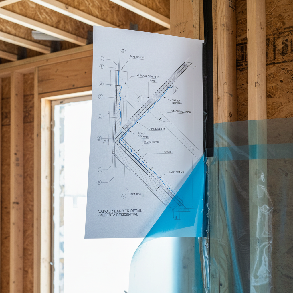
With winter temperatures often dropping well below -20°C and sharp fluctuations in relative humidity throughout the seasons, Alberta presents one of the most demanding environments for residential construction in Canada. In this context, vapour barriers serve a critical protective role: they minimize the risk of moisture infiltration, which threatens structural timber, insulation, and indoor health. The movement of water vapour through wall and ceiling assemblies-driven by the difference in vapour pressure between the warm interior and cold exterior-can quietly result in condensation, fostering conditions for rot, mildew, and degraded insulation values. Without a robust, properly placed, and continuous vapour barrier, even the most meticulously insulated assembly may fail its long-term performance objectives.
From a drafting perspective, this means every building detail must not only reference code standards but anticipate the real-world behavior of materials and assemblies under Alberta's climate stressors. The design intent must translate into construction-ready drawings that leave no uncertainty at field level.
Code Requirements for Vapour Barriers: Translating NBC 2023 Alberta into Buildable Details
Vapour Barrier Material Standards
Article 9.25.4.2 of the NBC 2023 Alberta Edition sets precise benchmarks for vapour barrier performance: a maximum permeance of 60 ng/(Pa·s·m²) tested via ASTM E96/E96M (desiccant method). This value is the threshold for controlling vapour transfer-and it represents a non-negotiable baseline, irrespective of material thickness or cost. In practical drafting terms, material callouts must always specify both the minimum thickness and the compliance standard, i.e., “6-mil (0.15mm) polyethylene vapour barrier, CAN/CGSB-51.34-M compliant, maximum 60 ng/(Pa·s·m²) permeance.”
The norm is to use clear or translucent polyethylene sheeting for above-grade walls and ceilings. However, aluminum foil vapour barriers or factory-applied vapor-retarding coatings (as used in some specialty insulated sheathing) may also be documented when dictated by assembly requirements or aesthetics. It’s crucial that the drafting documentation identifies the specific make, thickness, compliance testing, and location for each vapour barrier type-even if they visually appear similar on a drawing.
In basement and crawlspace applications or high-humidity envelopes, the temptation to use thicker poly (such as 10-mil) is common. Drafters must verify that the increased thickness does not introduce secondary issues (such as stiffness or difficulty creating airtight seals at transitions) and remains within NBC-specified requirements.
Placement in Exterior Wall and Ceiling Assemblies
Article 9.25.4.3 emphasizes continuity and proximity to the “warm side” of the insulation. Alberta’s climate makes this not merely a best practice but a functional requirement. Any drafting detail that places the vapour barrier distant from the drywall or behind multiple layers of other building elements increases the risk of interstitial condensation. Standard wall section details should indicate the vapour barrier layer directly behind the drywall and immediately inboard of batt or rigid insulation.
For ceiling assemblies, particularly where attic insulation is specified, the vapour barrier should be installed on the attic side of the ceiling joists, flush with the drywall, and extend over the entire conditioned area. Special annotation is warranted at ceiling-to-wall intersections, attic access hatches, and penetrations for services-these represent classic weak points in real construction, where drafter-specified details must preemptively address site execution.
Continuity - Junctions, Penetrations, and Transitions
Maintaining an unbroken vapour barrier is fundamental. The code allocates particular attention to the meticulous sealing of joints and penetrations. In practice, gap-free continuity is challenging at electrical boxes, piping, duct penetrations, rim joist intersections, and top/bottom wall plates.
Construction documents must not merely note “seal all penetrations,” but rather, demonstrate through enlarged details and annotated notes how each intersection is managed. For electrical boxes, this may entail the explicit callout for use of preformed, code-listed poly vapour box covers or airtight plastic boxes, with bead sealant indicated in section and plan. For service penetrations, specify compatible acoustical sealant (not typical latex caulking, which fails over time), and clearly delineate minimum overlap and taping/sealing zones at all seams (e.g., minimum 150mm (6”) overlap, then sealed with manufacturer-listed vapor-barrier tape).
Junctions at exterior wall/ceiling (particularly at the attic perimeter) should receive special attention in drafting sets. Include detail bubbles to larger-scale sections that illustrate the vapour barrier folding up and over top plates, sealed continuously to adjacent wall and ceiling membranes.
Integrating NBC Standards with Best-Practice Detailing
Proper Placement in Response to Alberta’s Temperature Extremes
In Alberta, mathematical thermal modeling routinely demonstrates dew points within assemblies when vapour barriers are misapplied. The drafter’s challenge is to represent not only the nominal wall build-up but also the precise vapor control line relative to thermal insulation. In a 2x6 wood-framed wall, for example, batt insulation fills the full cavity, while the 6-mil poly lays on the interior face, directly behind painted gypsum drywall. Installation errors-such as placing the barrier mid-cavity or behind foam sheathing-can shift the condensation plane into the thickness of the wall, causing persistent moisture problems invisible until major damage occurs.
This has practical implications for the drafter: every wall and ceiling assembly detail that might differ from the standard (such as walls with rigid exterior insulation, service cavity battens, or structurally insulated panels) requires a unique vapour barrier annotation. For example, walls with exterior rigid foam may (under certain conditions) allow for modified vapour control approaches, such as variable-permeance ‘smart’ membranes, but this must be explicitly referenced to NBC guidance and justified in notation based on climate zone modeling. Generic notes-“install vapour barrier as per code”-are insufficient.
Material Selection: Polyethylene Sheeting, Coatings, and Hybrid Assemblies
Although 6-mil polyethylene remains the workhorse for Alberta home construction, the last decade has seen the emergence of a wider palette of vapour control products. Aluminum foil laminates, kraft-faced batt insulation (not common in Alberta, but possible in custom builds), spray-on vapor-retarding paints, and proprietary airtight membranes are now appearing in niche applications. Each has uniquely different handling, taping, and sealant requirements-which, if not documented, can lead to compliance failures at inspection or actual field performance issues.
Drafters should go beyond simply specifying “vapour barrier” generically. Polyethylene must be called out by thickness and compliance standard, tapes must be vapor-barrier-rated (not just general construction tape), and all coatings, if used, must reference both application thickness and specific surface preparation. The vapor permeability of paint-on barriers, for example, varies with number of coats; assembly details should not rely on trades to “apply as required” but must specify manufacturer, number of coats, and location, backed up by cut sheets appended to the construction package.
In designs involving variable-permeance (so-called “smart”) membranes, document not only the product standard but the climate rationale. These products are allowed on foundation walls under NBC; the drafting set should include a note such as: “Variable-permeance membrane, Class II vapor retarder, min. perm 60 ng/(Pa·s·m²) in winter mode, installed as per manufacturer instructions and NBC 9.25.4.2.2. for below-grade assemblies.”
Sealing and Overlapping: Detailing for Durability
Effective sealing begins with proper overlapping-every join between sheets should show a minimum 150mm (6”) overlap, with mechanical fasteners spaced to prevent slumping or gaps. However, overlap alone does not suffice. Each seam requires sealing with compliant vapor-barrier tape-products that retain adhesion and vapor control under Alberta’s fluctuating temperatures.
From a drafting detail perspective, every joint, especially at ceiling-to-wall and poly laps behind stud walls, must be shown layered in the correct sequence, with hatching and notes indicating both tape application and sealant type. Box-outs (such as at plumbing chases or structural columns) demand special illustration-showing poly lapped around, cut and sealed at corners with compatible tape or mastic. For regular penetrations, construction details should suggest forming a ‘poly collar’-a rectangular or circular piece of poly sealed to the body of the barrier, then cut only as needed to fit, immediately sealed at the opening perimeter.
Sealant choice is not arbitrary: acoustical sealants are preferred, as they maintain flexibility and air/vapor control over decades, even under movement and minor compressions. Construction details should prohibit substitution with rigid caulks or materials liable to shrink or harden in the cold.
Avoiding Double Vapour Barriers: Hygrothermal Analysis in Drafting
Alberta’s climate makes the hazard of double vapour barriers very real. If two low-permeance barriers are installed-one on the warm side (such as poly) and another on the cold side (such as foil-faced board or certain sheathings)-the assembly can become a “moisture trap.” Even small incidental air leaks or construction moisture can accumulate between the layers, unable to dry to the interior or exterior, resulting in long-term damage.
In practice, the classic mistake is omitting to note the vapor resistance of all layers in the assembly. Drafters should document not just the explicit vapor barrier but also any secondary vapor-retarding layers. For example, where foil-faced foam sheathing is specified, the wall section must include a note: “No additional vapor barrier on exterior permitted. Interior vapor barrier omitted as per NBC Table 9.25.4.2. and assembly hygrothermal performance review.” Where only one barrier is present (as is typical), details should illustrate how higher permeability products (such as semi-permeable spray foams or kraft facing) in other parts of the assembly allow for dispersal of small quantities of moisture.
The drafting package should include cross-reference notes to mechanical ventilation-such as HRV/ERV requirements-since assembly drying potential partially depends on the building maintaining negative or balanced pressure, especially in homes with tight vapour barriers.
Air Barriers vs. Vapour Barriers: Coordination in Detailing
While some products serve as both air and vapour barriers (e.g., 6-mil poly, properly taped), the distinction must be observed in every detail. Air barriers stop airflow, which can drive vastly more moisture into cavities than vapor diffusion alone. In some assemblies, rigid foam or sheathing tapes act as the air barrier, while vapor control is left to other layers. Drafters must therefore identify, in every section, plan, and transition detail, which layers serve which purpose.
When using poly sheeting as a dual-purpose air/vapour barrier, construction details must require not only taped seams and sealed penetrations, but also continuous, uninterrupted runs over window and door headers, boxed in at all mechanical chases. In advanced assemblies (such as ZIP System or proprietary air barrier sheathings), the air barrier is exterior, so the interior vapor barrier is a secondary line of defense-each must be labeled and sequenced accordingly in the details and schedules.
Special Considerations for Alberta Assemblies: Adaptation Beyond the Minimum
High Moisture Generation Spaces
Kitchens, bathrooms, laundry rooms, and other high-humidity areas are major sources of moisture. Even with a perfect vapour barrier, the volume of water vapor generated can overwhelm assemblies, especially if penetrations are not scrupulously managed. For these critical rooms, drafting should include oversized details for typical wall/ceiling penetrations (e.g., vent fan housings, potlights), with specific notes on sealing the vapor barrier to fan housings and requiring gasketed or rated enclosures.
Mechanical schedules and detail references should specify high-flow, humidity-sensing exhaust systems, and code-compliant make-up air, so that local dew point is never persistently exceeded inside the envelope. At assembly level, consider specifying a vapor retarder with even lower permeance or, in some cases, slightly thicker poly, but always cross-checked with the code for condensation risks.
Thermal and Vapour Control at Foundation Walls
Basement foundation walls in Alberta create unique challenges, as below-grade assemblies regularly experience condensation at the interface of warm interior air and cold concrete. NBC allows use of variable-permeance vapor retarders (smart membranes) here, recognizing the need for the assembly to “dry” inwards if minor water ingress or condensation occurs.
Construction documents for finished basements should depict the vapor control layer continuous behind studs, up to the subfloor rim joist, and called out for both permeance and tape/sealant application. Where rigid foam insulation is adhered directly to the concrete, annotate whether it serves as vapor retarder (must meet the max 60 ng/(Pa·s·m²) value), and clarify whether a poly layer is required or could create double barrier problems. Detail the means for vapor barrier transition at slab/wall joints, window wells, and mechanical chases-areas notorious for accidental omissions.
Attached Garages and Transitional Spaces
Garage-to-house wall assemblies are a distinct concern under Alberta code. Since attached garages are often unconditioned but may be insulated, the shared wall (demising wall) requires a full vapor barrier to prevent fumes and water vapor from migrating into the residential space. Construction details should include notes such as: “Full-height, continuous 6-mil poly vapor barrier, sealed to rim joist and subfloor, tape-sealed to adjoining ceiling membrane. All electrical boxes to be vapour-tight units with gasket or flexible sealant.”
Details at the garage ceiling (below a living space) should reflect the vapor barrier separated from cold air in the garage, with any floor penetrations (plumbing, vents, posts) detailed to seal out both vapor and air. Include insulation baffles or “insulation dams” at bays to ensure vapor barrier is not punctured or compressed during insulation placement.
Comprehensive Wall and Ceiling Detail Development
Documenting Standard Wood-Frame Wall Assemblies
A typical above-grade 2x6 wall in Alberta is illustrated as follows in architectural detail sets:
- Exterior cladding (vinyl, brick, etc.)
- Drainage plane or sheathing wrap (e.g., Tyvek, as air barrier, occasionally vapor-resistant)
- Structural sheathing (OSB or plywood, noted for permeability-OSB is slightly vapor retarding)
- 2x6 studs at 400mm o.c., with R22-R24 batt insulation (type, thickness, and facing tailored to code and performance goals)
- 6-mil polyethylene continuous vapor/air barrier, with detailed taping at all seams and boxed-in penetrations, installed directly behind 12.7mm (1/2”) gypsum drywall
- Acoustical sealant at perimeter, penetrations, junctions at window and door frames, rim and top/bottom plates
Ceiling Assemblies and Attic Transitions
For attic roof construction in Alberta, a common failure occurs at the wall-to-roof connection, where the ceiling vapor barrier must turn up and seal to a vapor-tight attic membrane. Detail drawings should show the following:
- 12.7mm (1/2”) drywall ceiling, vapor barrier directly behind
- 6-mil poly vapor barrier, continuous, sealed at all laps and penetrations with compatible tape
- Insulation dam/baffle details where attic insulation meets eave soffit, to prevent blocking ventilation or compressing barrier
- Attic hatch detailed with gasketed weatherstripping and vapor barrier tape running tight to the framing-note requiring insulated hatch and airtight finish
- Junction at partition and perimeter walls showing vapor barrier envelope sealed, not just overlapped; sealant shown on each engagement between wall poly and ceiling poly
Penetration and Transition Details - From Practice to Drawing
Every electrical box, light fixture, plumbing riser, and vent flue that breaks the vapor barrier must be depicted in detail, not simply noted generically. For instance, at a light fixture in a cathedral ceiling, the detail should show:
- Poly folded around the electrical box location before install
- Box installed into the poly envelope
- All poly edges brought over the box flange and sealant bead applied before taping in place
- If vapor-tight boxes are used, specify the make/model or required performance class
- For larger penetrations, such as plumbing, show a pre-cut poly boot sealed to the membrane and pipe, with a secondary tape wrap for redundancy
Coping with Construction Sequence Realities
Even the best-detailed drawings face the realities of Alberta’s climate and construction logistics. Material handling, temperature swings during installation, and sequencing amid multiple trades all threaten vapor barrier continuity. Architectural drafters can mitigate these risks by specifying pre-assembled vapor blocks (such as box covers and boots), overlapping critical transition lines in the construction schedule, and providing redundancy in more complex assemblies.
For winter construction, drafters should annotate material recommendations for cold-weather adhesive performance (some tapes and sealants lose adhesion below -10°C) and specify that vapor barrier installation sequencing be coordinated to minimize exposure to temperature extremes and avoid wetting or wrinkling of poly sheeting. In renovation or addition contexts, include detail notes highlighting integration of new and existing vapor barriers-a notorious failure point-and reference field-verified taping and sealing.
Inspection, Testing, and Sustained Performance
Ultimately, the measure of vapor barrier success is not in the clarity of the drawings, but in the assembly’s as-built vapor control. Verification starts with a visual check of the membrane during framing inspection: is the poly continuous, or are there tears, gaps, or unsealed laps? Are boxes and pipes sealed as required? Is the vapor barrier tucked behind top/bottom plates and rim joists per detail? Drafters can support quality outcomes by including punch-list instructions in their detail sets.
Blower-door testing, while primarily an air leakage diagnostic, indirectly reflects the performance of vapor + air barrier assemblies. Drafters should note in construction documentation: “Vapor/air barrier continuity to be verified by air leakage testing per Step Code/municipal requirement; deficiencies to be remediated prior to insulation close-in.” Provide a checklist in the drawing set for field teams: lap/overlap verification, tape/sealant compatibility checks, documented installation photo requirements (especially for critical penetrations and transitions).
Common Mistakes and Advanced Detailing Solutions
- Overlooking Small Penetrations: Data cables, low-voltage wiring, and security system conduit are often ignored in vapor barrier detailing, leading to small but cumulatively significant leakage points. Best practice is to batch small wires at penetrations and provide details for booting and sealing even single-cable entries.
- Uncoordinated Trade Work: HVAC, plumbing, and electrical trades sometimes countermand vapor barrier installation by cutting large openings and “patching” after. Drafters should note work sequencing and recommend pre-installation meetings to reinforce the vapor barrier’s criticality.
- Poor Transitions at Additions/Renovations: Where new construction meets old, vapor barrier continuity is often neglected. Details should include demolition line/patching notes and reference field test requirements for all new/old junctions.
- Material Substitution Without Performance Verification: Careless substitution of tapes, sealants, or membranes results in assemblies that don’t meet code or lose performance quickly. Specify acceptable products with alternates pre-verified for compatibility and NBC compliance.
Climate Change, Evolving Assemblies, and Drafter Responsibility
Alberta’s climate is not static. Shifts in winter severity, precipitation patterns, and insulation standards mean vapour barrier detailing must remain dynamic-never simply “copied over” from past projects. Drafters must remain current with updates to the NBC, changes in performance expectations (such as net-zero targets), and new product releases. This demands rigorous product research, regular feedback from field installers, and ongoing connection with building officials.
Where energy retrofits or advanced assemblies (e.g., double-stud walls, exterior continuous insulation) are specified, traditional vapour barrier placement strategies may need adjustment. Drafter notes should reference hygrothermal analysis, explicit compliance with NBC tables, and build in flexibility where field conditions require deviation. Documenting a “typical” wall or ceiling assembly in Alberta is no longer enough-every project warrants site- and assembly-specific attention to vapor control line, material, integrated penetrations, and long-term drying potential.
Conclusion: Detailing for Code, Climate, and Real Life
Drafting code-compliant vapour barrier details for Alberta’s wall and ceiling assemblies is a blend of technical discipline, deep familiarity with climate impacts, and foresight about construction practices. Every line, note, and callout in the drawing set must not only align with the NBC 2023 Alberta Edition but also anticipate field realities: how will vapour control withstand decades of freeze/thaw, renovations, changing mechanical systems, and evolving energy targets?
By meticulously specifying materials, sequencing, and installation strategies, and by providing robust detail for conventional and unique assemblies, building professionals can deliver homes that are durable, comfortable, and energy-efficient-even on Alberta’s iciest days. The attention given in drafting, from initial schematic through to final working drawings, is the foundational defense against the silent, persistent threat of uncontrolled moisture. A rigorous, code-aligned approach-from assembly-level sections down to every last penetration or seam-is the best assurance of building health and compliance in Alberta’s variable, challenging climate.
Accuracy and buildability in vapour barrier detailing define the value Kingsway Drafting & Design brings to every Alberta residential project.