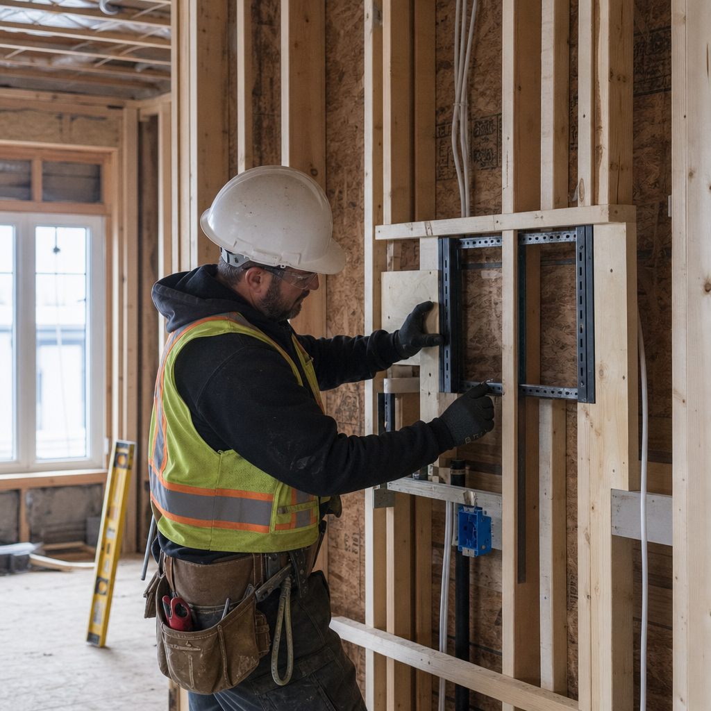
Proper TV wall blocking and wire concealment in Alberta homes is governed by specific detailing conventions, code call-outs, and plan-review protocols. Wall assemblies for flat-screen TV mounting, raceway concealment, and integrated equipment niches engage numerous code sections, require clear drawing cross-references, and are regularly flagged by municipal reviewers for missing or incomplete information.
Structural Blocking Detailing & Code Compliance (NBC(AE) Part 9)
Framed wall blocking for TV mounting is an engineered intervention governed by explicit dimensional requirements, fastening schedules, and code-mandated specifications in the National Building Code - 2023 Alberta Edition (NBC(AE)), notably Sections 9.3 and 9.23. Reviewers routinely cite non-conforming blocking, missing materials data, or insufficient documentation on plan sets, particularly at high-value finish walls.
Material Specifications and Dimensions
Blocking for wall-mounted televisions must match stud width for flush, load-bearing installation. The NBC(AE) Section 9.3.2.1. stipulates that wood used for blocking complies with CSA O141 ("Softwood Lumber"). For 2x4 walls, blocking is therefore 38x89 mm; for 2x6, it is 38x140 mm. Preservative-treated wood, when used (e.g., at exterior walls or framing near masonry), must remain compatible at all connections-this is enforced under Section 9.23.2.4., especially where cold-formed steel or proprietary anchors interface with treated timber.
Fastening Schedules and Load Requirements
Code-compliant fastening is indispensable for structural integrity. NBC(AE) Section 9.23.3.5. specifies that nails must be of sufficient length and diameter to penetrate deeply into both blocking and framing members. Plan sets almost universally annotate blocking to be face-nailed with 63 mm common nails, minimum 2 per end, or #10 screws with minimum 38 mm embedment into supporting framing for steel studs or engineered lumber. On review, redlines frequently note use of under-sized or non-code fasteners: “Blocking at TV wall must be fastened per 9.23.3.5. - Specify 2x 63 mm nails or equivalent screws per end.”
Where blocking serves a structural load-not only TV mass, but also multi-point mounts, equipment arms, or cabinetry-the blocking must be of the same material/species as the studs per Section 9.23.16, and of equal or greater depth. Drawings are redlined if substituted with blocking that's undersized, mixed species, or comprised of non-structural materials (e.g., MDF, plywood infill, or composite blocks) not designed for load-bearing duty.
Location, Spacing, and Dimensioning on Plan Sheets
Blocking is dimensioned and located on plans via direct dimensions (AFF or FFL), section symbols, and keynotes. Most drafters indicate height at 48-60" above finished floor (AFF) for typical TV mounting heights, but code does not prescribe location-only that it is explicitly dimensioned and referenced in elevations/sections. NBC(AE) 9.23.6.2. requires blocking at intervals not exceeding 1.2 m for fixture support-though most TVs are single-install, this establishes precedent for designer intent: heavy fixtures merit dedicated, precisely marked blocking on plans.
Typical notation: “Provide solid 38x140 mm wood blocking between studs at 1350 mm AFF, centers as shown for TV wall mount support. See Detail 2/A6.5.”
Detailing Standard Conventions in Architectural Drawings
- General notes: "Provide horizontal blocking at all wall-mounted TV brackets, min. 2x4 at 48"-60" AFF, secure per 9.23.3.5."
- Call-outs: Detail circle references (e.g., "TV MOUNT BLOCKING - See 3/A5.2") cross-referenced from plan and elevation views.
- Section cuts: Enlarged cut-throughs at TV walls showing blocking inset, nailed or screwed directly to adjacent studs, typically flagged with bold clouding or hex note for permit set clarity.
- Schedules: Some plan sets include a "Wall Blocking Schedule" indicating location, size, material, and anchor spec for each area requiring blocking-common in mid- to high-end infill homes after multiple review cycles introduce repetitive redline requirements to the design process.
Firestop and Fire-Blocking Integration
Where TV blocking intersects fire-resistance-rated or fire-separated assemblies, the NBC(AE) imposes requirements for both material and placement of firestopping. Section 9.10.16.1. and 9.10.16.2. require that blocking provide an effective barrier to fire spread and possess a flame-spread rating not exceeding 25. Drawings must specify fire blocking at tops and ends of cavities where blocking creates a potential concealed pass-through. Plan reviews frequently redline details such as: “Provide firestopping at all penetrations/voids at TV wall as per 9.10.16.2.-Include section specifying material and locations.”
Plan-Review Redlines and Corrections
- Lack of blocking for heavy fixtures: “Blocking absent at TV wall mount-revise plan to show solid blocking @ required height.”
- Non-compliant fasteners: “Specify 2x 63 mm nails or (2) #10 screws per 38 mm end per 9.23.3.5. Revise general notes.”
- Fire-blocking omissions: “Revise section - Firestopping required where blocking pierces rated assembly. Add fire-resistance rating callout per 9.10.16.2.”
Appropriate code call-outs, dimensioned locations, and referencing of blocking details on wall sections prevent delays at permit review and site inspection. Drawing clarity and code compliance are fundamental before subsequent trades coordinate low-voltage and power runs within the same wall system.
Integrated Electrical & Low-Voltage Raceway Systems: CEC/NBC(AE) Compliance
Wire concealment for TV feature walls-encompassing both high- and low-voltage-engages a web of CEC fill requirements, Alberta firestopping rules, outlet accessibility guidelines, and mandatory access panel detailing. The tangled cable nest behind a TV (power, HDMI, coax, Ethernet, speaker wires) can all too easily violate code or become a fire barrier breach without rigorous, up-front detailing in the permit set.
Raceway and Conduit Sizing
The Canadian Electrical Code (CEC) Rule 12-910 is explicit: maximum conduit fill is 53% for one conductor, 31% for two, 40% for three or more. Residential TV walls typically utilize EMT or rigid PVC, sized to accommodate the bundled conductors and future-proofed for occasional owner upgrades (e.g., from HDMI to fiber).
Example Calculation: For three #4 AWG RW90 conductors - 3x52.46 mm² = 157.38 mm²; divided by 0.40 = 393.45 mm² minimum conduit. A 27 mm (1") EMT, with a 40% fill area of 215.65 mm², would be insufficient-oversize to the next available size and document conduit size on the drawing. Permit reviewers will flag any absence of fill calcs, as in: “Conduit fill not shown - Provide schedule/calcs per CEC 12-910.”
Outlet Placement: Dimensioning for Accessibility and Code
Electrical outlet locations are governed by the CEC and must respect both spacing and mounting heights. General use receptacle outlets are to be mounted 300 mm (12") above finished floor (AFF), spaced not more than 1.8 m (6') apart, and no more than 1.5 m from any doorway. For TV feature walls, layouts must also account for equipment-specific power and low-voltage terminations at the intended mounting height (typically 48-60" AFF).
- Drawings frequently key outlets as: “E4 - 15A duplex receptacle, 120V, mtg. height 1350 mm AFF, refer to TV elevation 4/A5.2.”
- Plan reviewers regularly issue redlines such as: “Provide power at TV height per client intent-locate receptacle behind TV, not below, unless specifically detailed for cord chase.”
For low-voltage (HDMI, data, coax, speaker), wall-plates or pass-through grommets must be detailed at both TV mount and source component location, with conduit sized and dimensioned accordingly. All penetration points must appear on both the plan and elevation/section sheets, cross-referenced by sheet and detail number.
Firestopping Requirements at Wall Penetrations
Penetrations by electrical boxes or conduits in fire-resistance-rated walls must be firestopped per NBC(AE) 3.1.9.1.(1)(b), 3.1.9.2.(1), and 3.1.9.3.(1). Products must be listed, tested firestop systems (sealants, collars, or pillows tested to ASTM E814/UL 1479). Plan sets must not only show fire-rated assembly cuts, but delineate firestop product, trade name, and installation method at each detail.
- Common permit comments: “Electrical boxes in fire-rated walls require firestop systems-call out rating and UL system for each location.”
- Section details should indicate: “Firestop at all conduit/wire penetrations-‘Hilti CP 606 firestop sealant or equivalent’, install per manufacturer’s detail.”
Access Panel Specification: Concealed Services and Inspection
Any junction box, split-plate, or media component concealed within a wall or niche must be service-accessible. The NBC(AE) and CEC both require access panels minimum 300x300 mm (12"x12") unless code allows a smaller format by specific listing. Access panels in fire-resistance-rated partitions must match the wall's fire rating (e.g., 1-hour rating for 1-hour walls).
- Drafting call-out: “Access panel AP-1, 305x305 mm, 1-hr fire-rating, refer to 6/A6.4.”
- Inspection note: “Install AP-1 centered per detail for junction box access-maintain unobstructed by finish system or TV bracket.”
Permit reviewers frequently redline the omission of access panels for equipment or wire terminations, especially in fully concealed or high-finish walls: “Add fire-rated access panel for service to concealed junction at TV niche per 3.1.9.2 and CEC rule 12-3032.”
Drawing-Sheet Call-Outs for Electrical Raceway Systems
- Electrical plan symbols: differentiated between EMT, PVC, flexible metal conduit (FMC)-with sizes called out on electrical plan legend.
- Keynotes: “K214 - Raceway for HDMI/data, 27 mm EMT, top-plate to 1350 mm AFF, firestop at all penetrations. See Detail 9/E3.1.”
- Schedule: “Raceway/Outlet Schedule - Type: EMT; Size: 27 mm; Location: TV wall, fridge back, island; Detail: 2/E3.2.”
- Dimension string: “Conduit drop at 350 mm from wall corner, terminate at 1350 mm AFF.”
Detail sheets must cross-reference between architectural and electrical sets, e.g., “See 2/A8.1 for blocking; wire chase elevation 5/E3.2.” Gaps in this coordination trigger review comments and jobsite change requests (RFIs).
Detailed Plan Set Integration & Drawing Standards for TV Wall Components
Integrating TV wall features across multi-discipline plan sets in Alberta homes requires both precision and redundancy-ensuring that details recorded in architectural, electrical, and structural sheets are coordinated, legible, and directly responsive to both code and trade requirements. Inconsistencies here are the direct cause of ambiguous RFI traffic, construction delays, and failed inspections.
Layering Conventions in CAD and Sheet Setup
Adhering to National CADD Standard conventions, wall construction is delineated on A-WALL layers; TV-specific blocking or mounts are assigned A-FURN or A-EQPM layers; electrical raceways and boxes are set on E-POWR or E-LOWV as appropriate. This ensures plan, section, and enlarged details can reference the same feature without accidental omission or duplication when xrefs, layer control, or set coordination are performed.
Permit review comments often state: “Electrical scope not coordinated-blocking shown on A6.2, not cross-referenced on E3.1. Revise and resubmit full coordination.” Robust layering clarifies intent for every trade.
Annotation Keynotes, Cross-Referencing, and Sheet Organization
- Keynotes on Plan: Used for recurring requirements-“K101: Provide 2x6 blocking @ 1350 mm AFF for TV, per 3/A5.1.” or “K106: Concealed conduit drop for TV, 27 mm EMT, refer to E4.2.”
- Section References: On floor plan or elevation, add call-out bubbles: “See Section A-A, Sheet A6.2 for TV blocking and chase details.”
- Detail Schedules: "Wall Blocking & Raceway Detail Schedule: Refer Detail #, Elevation Ref, Material Spec, Fastener Schedule, Firestop Note."
- Drawing Index: “TV feature wall and raceway: see A5.1, A6.2, E4.2, E5.1.”
Whereas typical builder-grade sets rely on legend descriptions, multifaceted TV wall systems use detailed keynoting and heavy cross-referencing-confirmed in practice by review comments such as: “Blocking shown on A5.0 but not dimensioned, no detail reference. Add detail bubble or keynote linking plan to section/elevation.”
Cross-Disciplinary Plan Coordination
TV wall systems appear in both Architectural and Electrical sheets, with raceway/blocking details also sometimes present in Structural if wall modifications affect load paths or require engineered headers. It is common for architectural plans to reference or cloud changes for field review:
- “Clouded revision: Additional blocking for TV arm-coordinate with E4.2 for new wire drop, see SK-5 for engineered stud arrangement.”
Failure to coordinate can produce field RFIs and direct redlines, e.g., “Electrical route collides with supplied blocking - clarify which takes precedence-provide coordinated detail.”
Specific Sheet and Detail Examples
- Plan Keynote: “K215 - Provide solid 2x6 wood blocking between studs @ 1500 mm AFF for TV mounting. See Section 2/A6.2.”
- Section Note: “2x6 SPF #2 horizontal block, face-nailed to each stud w/ (2) 63 mm nails per end, typ. 1500 mm AFF. Pre-run 27 mm EMT for HDMI/data per E4.2.”
- Elevation Call-out: “Equipment niche w/ cable pass-through, refer Detail 6/A8.3, wire path per E5.6.”
Addressing Plan Review Comments & Jobsite RFIs for Concealed TV Systems
Detailed documentation of TV wall assemblies is frequently interrogated by municipal plan reviewers. Among the most common redlines and post-permit jobsite RFIs/ASIs in Alberta:
Common Plan-Review Comments and Redlines
- Fireblocking at Concealed Cavities: “Provide continuous fire blocking at top and ends of wall cavity used for wire chase per 9.10.16.1/2. Add to section and note in legend.”
- Structural Verification: “Modification to studs at TV wall-submit stamped structural detail showing blocking/jack arrangement does not reduce wall capacity.”
- Concealed Electrical Compliance: “Electrical wire for TV chase must be CEC approved for in-wall use-conduit/raceway not specified. Revise plan to indicate pathway, size, and access per CEC 12-510.”
Documentation Protocols
Drawings must include not only plan call-outs and detail references, but also explicit general notes and legend statements that clearly instruct trades and inspectors. These typically include:
- General Note: “All blocking and wire chases for TV feature walls shall be installed per detail, with fire-rated firestop at all rated assemblies. Maintain access to all junctions.”
- Legend Add: “FB = Fire blocking per 9.10.16, typ. at top/end of cavity, see Section 4/A6.2.”
All plan modifications generated from field issues (RFIs, ASIs) must be documented on revised drawings, clouded, and referenced by City permit number and SK/revision #. Field directives lacking formal documentation are categorically rejected by Alberta AHJs (Authorities Having Jurisdiction).
Field Coordination Strategies
- Pre-Install Coordination Meetings: Before rough-in, organize a trade review meeting with framing, electrical, and drywall contractors to inspect blocking, cable paths, and all required access or firestopping prior to boarding-minimizing costly drywall “surgery.”
- Mid-Install Inspections: Conduct interim framing inspections, emphasizing firestop placement, integrity of wall zone, and accessibility of junctions or low-voltage boxes.
- RFIs/ASIs Response Tracking: Site field changes (e.g., bracket height, wire chase size, niche depth) require documented responses with revised details added to clouded drawing sets for inspection records.
Common field RFI: “Can blocking be dropped 150 mm to align with final TV bracket?” Standard response is to issue ASI with updated elevation, revised section marker, and a new clouded area on most current drawing backgrounds-ensuring inspection aligns with construction.
Fireblocking and Serviceability
TV feature walls using deep chases or equipment niches become de facto service spaces. Fireblocking at intervals ≤3 m vertically and ≤20 m horizontally must be detailed, with each cavity termination shown within the section detail and general fireblocking schedule. Materials must be 1-hour fire-resistance-rated if located in a rated assembly; gypsum, mineral wool batts, or code-listed firestop composites are most commonly specified. Redlines arise when access panels to in-wall junctions or chases are omitted or undersized: “Add 305x305 mm fire-rated access panel for concealed TV niche controls-reference detail and rating.”
Special Conditions: Sound Isolation, HVAC Integration, and Accessibility
TV wall assemblies intersect technical requirements well beyond framing, wiring, and finish-affecting acoustics, mechanical systems, and accessible design. The detailing and coordination for these special conditions have direct code-driven impacts on plan reviews, redlines, and construction.
Sound Isolation Performance for TV Walls
For party walls, separating assemblies, or media rooms, the NBC(AE) mandates a minimum Apparent Sound Transmission Class (ASTC) of 47 or STC 50 (Section 9.11.2.1.). Wall constructions must be annotated on plan sets with the relevant sound test performance and component schedule (e.g., resilient channel spacing, insulation product, and thickness).
- Standard note: “2x6 staggered stud, 150 mm mineral batt, 2x 16 mm Type X gyp each side, RC-1 @ 400 mm OC, ASTM E90 test assembly with STC 54.”
- Section detail: “Seal all wire penetrations with acoustic sealant and firestop, maintain full insulation density behind TV niche.”
Plan review redlines may read: “TV wall niche penetrates rated party wall-confirm resulting assembly meets/exceeds ASTC 47. Provide sound test or increase wall spec.” All trades must be required to reseal, re-insulate, and re-block any openings created or disturbed by TV features prior to close-in.
HVAC Integration and Duct Routing Near TV Features
Alberta enforcement of HVAC noise and placement in specialty walls follows good engineering practice and assumes compliance with the NBC(AE) intent for separated sound/noise zones. Where supply or return ducts cross a TV wall or equipment niche, plans must show:
- Sound-attenuating duct boots, lined/isolated trunks, or flexible ducts as needed-call-out on plan: “Include sound attenuator on R/A duct passing through TV wall. All duct penetrations grommeted/sealed, see M4.2/E5.1.”
- HVAC design does not undermine wall structure: “Duct in TV niche coordinated with wall framing/structural detail, maintain structural integrity per Part 4.”
Plan reviews may flag HVAC details: “Duct passing through TV wall not coordinated - revise plan to show isolator and maintain wall thickness and rating.”
Accessible Design: TV Wall Mount Heights and Clearances
The NBC(AE) requires mounting heights and reach ranges for operable controls in accessible spaces per Section 3.8. Controls (power, AV terminations, remote interfaces) must be mounted between 900 mm and 1200 mm AFF. TV wall mounts in accessible suites and public/common areas must be dimensioned to 90-120 cm AFF.
- Dimension strings on plan: “TV wall control panel at 1020 mm AFF (centerline), 760 x 1220 mm minimum clear space in front.”
- Enlarged plan inset: “Equipment niche: shelf, touchpanel, and power mounted valid for accessible reach. Section 8/A8.2.”
Review comments for accessibility: “Control interface for AV not within accessible reach range; revise mounting heights per 3.8.3.3.”
Details for Sealing, Insulation, and Acoustic/Fire Integrity
Wall assembly types must be cross-referenced among wall schedule, section, and details. Insulation type and depth, presence of resilient channel, and sealing methods for penetrations are called out on both plan and section. Careful attention to sealing around electrical and raceway penetrations maintains both STC and fire-resistance integrity:
- Acoustic sealant detail in section: “Seal wire/conduit penetration w/ Tremco Acoustical Sealant and listed firestop-restore mineral batt to full thickness.”
Conclusion
The architectural drafter’s plan set is the contract for construction, coordination, and code compliance-nowhere more so than at the modern TV feature wall in Alberta homes. Every blocking member, conduit, junction access, and firestopping detail must be fully annotated, dimensioned, cross-referenced, and code-cited to avoid review delays and jobsite ambiguity, as evidenced by real-world redlines and field corrections. Structural, electrical, fire, acoustic, and accessibility requirements intersect in these coordinated assemblies. Only rigorous drawing standards and devil-in-the-details annotation can keep Alberta projects on schedule and in compliance-all backed by the diligent, code-driven drafting expertise at Kingsway Drafting & Design.