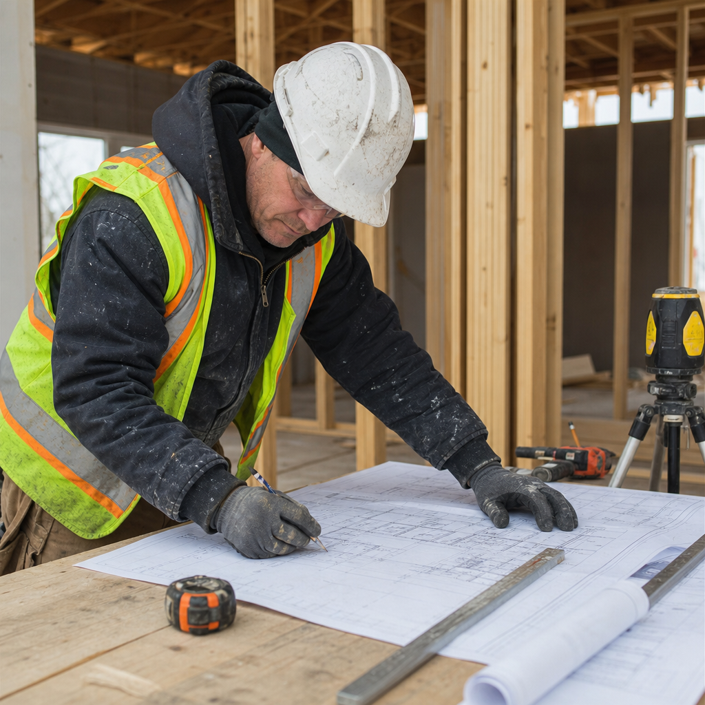
Non-load-bearing interior wall framing beneath roof trusses in Alberta homes must be executed with precision. Roof trusses are susceptible to seasonal upward movement - known as truss uplift - which, if unaccounted for, leads to cracking at ceiling-wall junctions and fails both inspection and homeowner expectations. Proper protection against truss uplift is not only a matter of good practice but is directly governed by the Alberta Building Code (ABC), coordinated plan-to-site detail, and robust communication among all design and site parties. From architectural drawings through permit review, specifications, and construction, every detail must show explicit compliance, dimensional clarity, and buildable information.
ABC 2020 Division B, Part 9: Non-Load-Bearing Wall Framing Under Roof Trusses
Stud Size, Spacing, and Wall Height: Table 9.23.10.1 Compliance
Section 9.23.10.1 of the Alberta Building Code 2020 Division B governs the allowable stud size and spacing for non-load-bearing interior walls under trusses. According to ABC 9.23.10.1(1), for these partitions:
- Minimum Stud Size: 38 mm × 38 mm
- Maximum Stud Spacing: 400 mm on centre
- Maximum Unsupported Wall Height: 2.4 m
When any of these thresholds - particularly the wall height - are exceeded, drawings must bear a clear indication that engineering under Part 4 is required. It is common to see plan-review comments such as “PARTITION WALL HEIGHT EXCEEDS TABLE 9.23.10.1, PROVIDE ENGINEERED DESIGN,” prompting detail revisions or additional professional involvement.
Bracing, Lateral Support, and Finishes: 9.23.10.2 and 9.29 Cross-Referencing
Although these walls are non-load-bearing, lateral stability is still a code concern. ABC 9.23.10.2 clarifies that such walls achieve required bracing when finished in accordance with Section 9.29 (typically, drywall or gypsum board secured to both sides). On plan sheets, the standard drawing convention is to note directly in typical wall section details and general notes: “INTERIOR PARTITIONS TO BE FINISHED BOTH SIDES AS PER ABC 9.29 FOR LATERAL SUPPORT.” Failure to specify this can trigger permit reviewer redlines: “PROVIDE LATERAL BRACING AT NON-LOAD-BEARING WALLS PER ABC 9.29.”
Stud Orientation: Permissible Flat Stud Layouts
ABC 9.23.10.3(1) allows for studs to be installed “on the flat” (38 mm face parallel to the wall finish), provided the wall falls within the table’s maximum derivations. Drawings depicting flat-stud partitions must include explicit general notes and wall type keying. Omitted or ambiguous detailing here remains a frequent plan-check deficiency. Typical plan reviewer feedback: “CONFIRM STUD ORIENTATION IN N.L.B. WALLS; FLAT STUDS ARE NOT TO BE USED FOR WALLS EXCEEDING 2.4 M HEIGHT.”
Standard Drawing-Sheet Call-Outs and Detail Conventions
Plan production conventions require repeated, unmistakable cross-referencing of ABC requirements. Key notes typically read:
- “ALL NON-LOAD-BEARING INTERIOR PARTITIONS TO BE FRAMED WITH 38x38 MM STUDS @ 400 MM O.C. MAX, U.N.O. - SEE ABC 9.23.10.1”
- “REFER TO SECTION 9.23.10.2/9.29 FOR LATERAL SUPPORT AND FINISH REQUIREMENTS”
- Wall section details show precise dimension lines marking required member sizes, gaps, and finishes, referenced by both code paragraph and symbol markers.
Persistent omissions at this stage - missing code references, non-dimensioned heights, unkeyed wall types - account for a significant proportion of back-and-forth corrections with both plan reviewers and field inspectors.
Architectural Detailing: Depicting the Truss Uplift Gap, Dimensions, and Notes
Sectional Representation: The 3/4" (19 mm) Gap
While the Alberta Building Code does not prescribe a numeric gap for truss uplift, Alberta’s builders, drywallers, and inspectors universally require a minimum 3/4" (19 mm) clear space between non-load-bearing top plates and the bottom chord of trusses. Drawings must show this directly:
- Section cut at each truss/partition intersection with dimension arrow from top plate to bottom chord, labeled “3/4" (19 mm) MIN. CLEAR GAP FOR TRUSS UPLIFT.”
- Accompanying keynote or callout directly on the section, e.g.: “PROVIDE 3/4" MIN. CLEARANCE ABOVE N.L.B. WALL TOP PLATES TO B.C. OF TRUSS FOR UPLIFT MOVEMENT.”
Enlarged details may supplement this with exploded views of fastening hardware, clips, and drywall slip connections.
Framing Plan, Wall Type Schedule, and Enlarged Detail Dimensioning Strategies
Framing plans must distinguish all non-load-bearing partitions that pass under trussed ceilings, typically using a unique plan symbol or hatch. Accompanying keynotes or leader tags must point to both the larger wall-type schedule and the specific truss uplift detail, e.g.:
- Keynote “T1”: “SEE DETAIL 3/A512 FOR TRUSS UPLIFT CLEARANCE AND FASTENING REQUIREMENTS”
- Wall Type WT2: “INTERIOR PARTITION, NON-LOAD-BEARING: 38x89 STUDS, FLOATING TOP PLATE WITH MIN. 3/4" CLEARANCE TO TRUSS B.C.”
General notes sections universally include an instruction such as: “ALL NON-LOAD-BEARING INTERIOR WALLS UNDER TRUSSED ROOFS SHALL HAVE A MINIMUM 3/4" (19 mm) CLEARANCE FROM TOP PLATE TO BOTTOM CHORD OF TRUSS.”
Keynoting, Legends, and Detail Referencing
On wall sections and details:
- Keynote numbers (e.g., “5”) reference truss uplift hardware, with a corresponding schedule: “5. TRUSS UPLIFT CLIP, SIMPSON STRONG-TIE HSLU, SEE SPEC.”
- Truss uplift clearance is keyed (e.g. “7”) and in the legend reads: “7. 3/4" (19 mm) MIN. SLIP GAP.”
The clarity in referencing, redundancy across plan, section, and schedule, and precise dimensional annotation is essential. Vague callouts or bolded wall types without clear gap or hardware notation are common plan-review failures.
Fastening Methods: Specifying Truss Uplift Hardware and Drywall Attachment
Approved Truss Uplift Hardware: Slip Plates, Uplift Clips
Field execution and inspection rely on explicit drawing notes with manufacturer and hardware call-outs. Acceptable solutions in Alberta involve:
- Slip Plates: Steel or zinc-plated slip connectors between the top plate and truss chord, specifically allowing for vertical movement. Plans typically call out, e.g., “PROVIDE SLIP PLATE (GYPSUM ASSOCIATION STD-101 OR EQ., 16 GA. GALV. STEEL) BETWEEN ALL N.L.B. TOP PLATES AND TRUSS B.C.”
- Truss Uplift Clips: Proprietary hardware that secures the truss while permitting slip. Architecturals and structural schedules often specify, “SIMSPON STRONG-TIE HSLU CLIPS OR LSUC UPLIFT CLIPS AS PER MFR. INSTRUCTIONS AT ALL INTERSECTIONS OF TRUSS AND N.L.B. WALLS.”
Detail sheets illustrate clip orientation, nailing patterns, and any anti-shear blocking, with corresponding note: “N.A.I.L. IN ACCORDANCE WITH MANUFACTURER REQUIREMENTS - TYP.”
Drywall Attachment: Blocking, Drywall Clips, Fastener Scheduling
Preventing truss uplift damage at the ceiling/wall joint requires that drywall not be rigidly attached at the intersection. Drawing conventions include:
- Ceiling drywall termination “float”: Do not fasten ceiling drywall to bottom chord within 400 mm (16") of wall intersection. Typical note: “DO NOT FASTEN CEILING DRYWALL WITHIN 400 MM OF PARTITION - PROVIDE DRYWALL CLIPS OR BLOCKING AS PER DETAIL 7/A512.”
- Specify blocking (where required) so as not to restrict truss slip. Details may show 2x4 blocking fastened only to the top of the wall, with a gap to the truss.
- Use of F-clips or similar drywall brackets called out in scheduling: “PROVIDE SHEETROCK F-CLIPS OR APPROVED EQ. AT ALL FLOATING CORNERS - SEE SPEC.”
Dimension lines and fastener callouts must be precise: “CEILING BOARD TO BE FASTENED WITH 2-1/2” DRYWALL SCREWS @ 300 MM O.C. EXCEPT AT FLOATING JOINTS - DO NOT FASTEN WITHIN 400 MM OF WALL.”
Fastener Types, Spacing, and Specific Notes
Drawings and specifications must spell out hardware needs:
- Truss Clips/Plates: Fasten using specified screws or nails (e.g., “No. 10 x 1-1/2” screws, 2 per leg minimum, per manufacturer”).
- Drywall: 2-1/2” coarse thread drywall screws at 300 mm O.C. for standard attachment. At floating corners, instructions clarify not only fastener omission but the use of clips or alternative attachment methods.
- “CEILING DRYWALL AT TRUSS/INTERIOR WALL INTERFACE TO BE FLOATING AS PER DETAIL, NO FASTENERS WITHIN 400 MM (16”) OF WALL - TYPICAL WHERE SHOWN.”
Schedules summarizing all connections by location, hardware, and fastener pattern help ensure both estimation and site-work accuracy.
On-Site Pitfalls: Framing Errors Addressed in Shop Drawings
Repeated failures in field review-primarily due to unclear drawings-include:
- Omission of hardware: Trusses nailed directly to partition top plate, negating any uplift protection.
- Incorrect fastener use: Drywall rigidly fastened through both ceiling and wall, causing cracks at joint lines.
- Non-rated or unapproved hardware substitution: Shop drawing reviews and submittals must show correct product (e.g., “Submit Simpson HSLU data for review prior to installation - no substitutions without written approval”).
Shop drawings are the corrective battleground for restoring code-compliant details when absence or ambiguity in the original construction documents causes confusion.
Permit Review Redlines and Proactive Detailing for Approval
Permit Review: Common Comments and Deficiencies
City of Calgary, Edmonton, and other Alberta Authority Having Jurisdiction (AHJ) review staff scrutinize truss uplift accommodations on every permit set. Common plan-review comments include:
- “PROVIDE DETAIL SHOWING 3/4" MIN. CLEARANCE BETWEEN NON-LOAD-BEARING PARTITION TOP PLATE AND TRUSS.”
- “SPECIFY DRYWALL CONNECTION METHOD AT INTERSECTIONS TO ACCOMMODATE TRUSS UPLIFT.”
- “TRUSS SHOP DRAWING TO CONFIRM UPLIFT REQUIREMENTS - COORDINATE WITH ARCH. DETAILS.”
Missing or generic details, incomplete general notes, and absent dimensioning are flagged on nearly every set not drawn to current best practices.
Typical Reviewer Remarks and Detail Shortcomings
Reviewers will specifically ask:
- “CLARIFY IF PARTITION WALLS SHOWN UNDER TRUSSES ARE N.L.B. OR L.B.”
- “DO NOT FASTEN TRUSS DIRECTLY TO TOP PLATE FOR N.L.B. PARTITIONS.”
- “SHOW SLIP JOINT OR HARDWARE AT WALL/CEILING JUNCTIONS.”
Typical drawing failures corrected by reviewer mark-up include missing enlarged section details, no “floating corner” notes, omitted schedule lines for truss clips or drywall fasteners, or relying on generic stock details that do not meet specific site or code conditions.
Strategies for Clear Communication and Approval
The effective permit set layers multiple lines of information across:
- Large-format, dimensioned wall sections at every unique truss/partition condition
- General notes box on each relevant sheet: “ALL N.L.B. INTERIOR WALLS SHALL BE FRAMED AND FINISHED IN ACCORDANCE WITH ABC 9.23.10.1 AND 9.29, AND WITH 3/4" MIN. UPLIFT GAP AS PER DETAIL 5/A521.”
- Reference to truss shop drawings: “TRUSS SUPPLIER TO PROVIDE UPLIFT VALUES; ARCHITECTURAL TO COORDINATE GAP AND CLIP DETAIL AS SHOWN.”
- Explicit, instruction-level notes at relevant connections: “DO NOT FASTEN DRYWALL WITHIN 16 IN. OF CEILING/WALL INTERFACE - USE APPROVED FLOATING CORNER DETAIL - SEE 7/A525.”
Consistently, permit reviewers require direct, dimensioned, and referenced details-a single buried general note or legacy stock detail is not considered adequate.
Coordination: Architectural, Structural, and Truss Shop Drawings for Uplift Detailing
Drawing Set Alignment: Wall, Structural, and Truss Coordination
Non-load-bearing wall uplift protection is a classic test of multi-discipline drawing integration. Architecturals set the room layout and wall types; structurals specify wall bracing and sometimes hardware; truss manufacturers provide shop drawings that determine both magnitude and location of truss uplift. The entire design and permit process depends on aligning these sources:
- Architectural drawings indicate wall status (load-bearing or not), gap, hardware, and finish.
- Structural notes may specify: “TRUSS UPLIFT AT N.L.B. WALLS TO BE ACCOMMODATED - DO NOT PROVIDE RIGID CONNECTION. SEE DETAIL AND SPECS.”
- Truss shop drawings must report uplift magnitude (e.g., “MAXIMUM ESTIMATED UPLIFT: 21 mm AT LOCATION X”), driving architectural gap specification.
Explicit call-outs on all three drawing types, referenced by detail and code section, must remain in agreement-otherwise confusion and field conflicts arise.
Field Scenarios and Contractor Queries
Jobsite error is inevitable where drawings are ambiguous. Typical scenarios include:
- Framers nail the partition top plate directly to the truss bottom chord, having never seen detail sheets or only reading generic notes.
- Drywallers fasten ceiling gypsum board directly to both the truss and wall top plate at the intersection, negating floating detail benefits and causing subsequent cracking.
- Field modifications: Site supervisors instruct additional blocking or fastening “for strength,” thereby locking out required movement.
Normal builder questions to drafter, general contractor, or site supervisor invariably include: “Do we leave a gap here?”, “Are we allowed to attach the truss to the wall?”, “How is the drywall held up if it isn’t fastened at the corner?”
Proactive Drawing Notes, 'Do Not Nail' Call-Outs, and Fastener Schedules
To preempt costly mistakes and late clarifications:
- Employ aggressive “DO NOT NAIL” clouded call-outs directly above walls on framing plans and section details.
- Specify: “TOP PLATE OF N.L.B. PARTITIONS SHALL NOT BE RIGIDLY ATTACHED TO TRUSS BOTTOM CHORD - PROVIDE 3/4" MIN. GAP WITH UPLIFT CLIP (SEE SCHEDULE).”
- Add sequence notes: “INSTALL CEILING DRYWALL PRIOR TO WALL BOARD; CEILING BOARD TO FLOAT AT CORNER AND BE FASTENED WITH CLIPS ONLY - DO NOT PLACE FASTENERS WITHIN 16" OF WALL.”
- Provide fastener schedules on detail sheets, explicitly stating approved fasteners, hardware, and spacing per detail reference.
Where drywall floating cannot be achieved due to room geometry or finish constraints, specs must recommend alternative strategies such as control joints or heavier flexible compounds, all with drawing note cross-references.
Field Modification Protocol: Coordination and Communication
Even with the best drawn details, unplanned field changes occur. Drawings and specifications should instruct: “ANY MODIFICATION TO INDICATED FASTENING, BLOCKING, OR HARDWARE DUE TO FIELD CONDITIONS REQUIRES WRITTEN CLARIFICATION FROM DESIGN TEAM PRIOR TO INSTALLATION.”
Shop submittal review is a vital backstop; rejected submittals cite missing hardware call-outs, noncompliant uplift gaps, or unspecified fastener types and require coordinated revisions prior to acceptance.
Material Schedules, Dimensions, and Manufacturer Call-Outs
Material and Hardware Specifications On Drawings
All material and hardware requirements must appear on the architectural drawing’s material and connections schedule, referenced by symbol, note, and detail:
- Studs (non-load bearing): 38 x 89 mm SPF No. 2 or better @ 400 mm O.C. max, unless engineered otherwise
- Truss uplift clip: Simpson Strong-Tie HSLU or LSUC, or approved equal
- Drywall clip: Sheetrock F-Clip or equivalent, installed at all floating intersections, as per manufacturer’s instructions
- Fasteners: No. 10 x 1-1/2" screws for clips, 2-1/2" coarse thread drywall screws @ 300 mm O.C. on ceiling; no fastening of ceiling board within 400mm of N.L.B. wall intersection
- Uplift gap: 3/4" (19 mm) minimum clearance above top plate of all non-load-bearing partitions under trusses
Manufacturer’s Instructions and Substitution Procedures
Spec notes are vital: “INSTALL ALL UPLIFT, SLIP, AND DRYWALL CLIPS STRICTLY PER MANUFACTURER’S PUBLISHED INSTRUCTIONS. SUBSTITUTIONS REQUIRE WRITTEN APPROVAL FROM DESIGN PROFESSIONAL AND AHJ.”
Conclusion: Enforcing Clarity, Compliance, and Constructability
Truss uplift protection at non-load-bearing interior walls in Alberta is a multifaceted drafting and construction coordination challenge-from dimensioned, code-referenced wall sections and robust general notes, to proprietary hardware call-outs and builder-proof field details. The ABC 2020 requirements (9.23.10.1, 9.23.10.2, and 9.29), along with local permit reviewer expectations and manufacturer instructions, must converge in every permit and construction drawing set. Standard drawing conventions-dimensioned 3/4" uplift gaps, explicit “do not nail” notes, keynoted hardware, and prescriptive fastener schedules-are essential to prevent costly jobsite mistakes and rework. Every detail, note, dimension, and schedule entry must speak with one coordinated voice to permit reviewers, trade contractors, and field inspectors. As truss uplift will continue to challenge Alberta homes in years ahead, robust, code-coordinated drafting remains the frontline defense, and precision in detail is the difference between a project that passes, and one that cracks-literally and figuratively.
For clarity and compliance in every Alberta home, Kingsway Drafting & Design is committed to code-accurate detail, coordinated documentation, and buildable solutions at every intersection of drawing and construction.