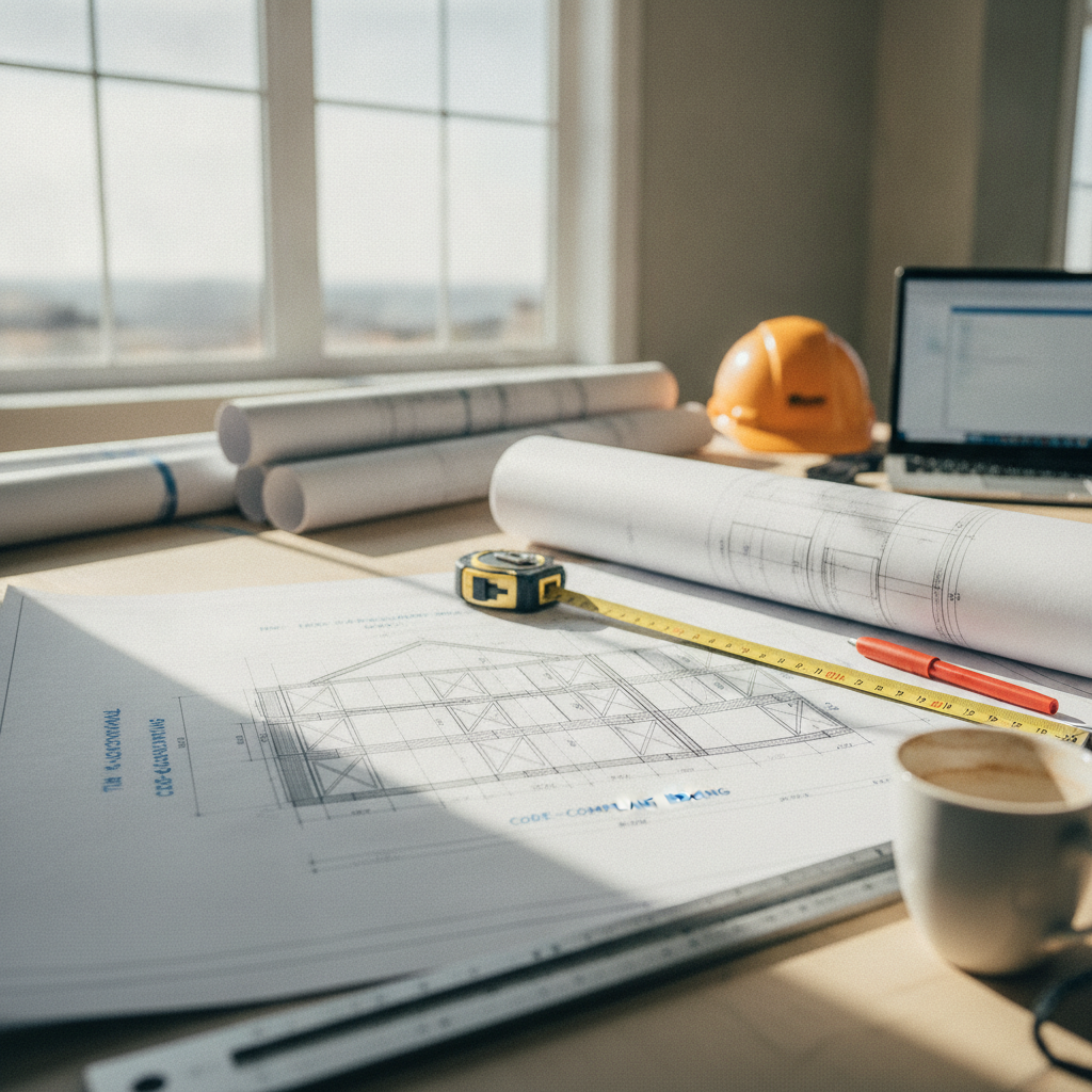
Tall non-load-bearing walls-frequently rising above 3.6 meters (11.8 feet)-are increasingly common in contemporary Alberta homes, especially in open-concept living spaces, dramatic entryways, and rooms with vaulted ceilings. While these walls do not support vertical structural loads from above, their very height subjects them to considerable lateral pressures, particularly from wind and, to a lesser extent, seismic activity. Such lateral forces, if not counteracted, can lead to problematic wall deflection, gapping at connections, drywall cracking, separation at trim intersections, and in severe cases, partial or complete wall failure.
Walls of this scale act as slender cantilevers when unbraced, and their geometry amplifies the possibility of lateral movement-a phenomenon accentuated in Alberta’s climate where wind events are frequent and sometimes severe. Moreover, tall non-load-bearing walls are often misunderstood as being less critical since they don’t underpin floor decks or roofs. However, improper bracing can undermine everything from plaster integrity to the operation of doors and windows within or adjacent to these walls. All of this underscores the importance of rigorous, code-informed drafting and specification of bracing details during the design stage.
Critical Code Requirements Under NBC(AE) 2023 for Bracing Tall Walls
Enforced across Alberta as of May 2024, NBC(AE) 2023 provides comprehensive direction on bracing requirements, tightly prescribing the strategies that must be embodied in both construction and drawing packages. Key compliance points appear within Part 9, with direct reference to:
- 9.23.13 - Bracing to Resist Lateral Loads Due to Wind and Earthquake: Detailed measures are provided to address high lateral loads, encompassing everything from sheathing thickness to nailing patterns, and the need for robust material choices and assembly methods. Exceeding prescribed wall heights or building in ‘high’ or ‘extreme’ lateral force regions requires enhanced measures outlined in this section.
- 9.23.6.1 - Anchorage of Building Frames: Mandates direct anchorage of walls to foundational elements unless a structured analysis by engineering demonstrates an alternative. Bracing design and anchor specifications are integrally linked in permit submissions and on-site inspections.
Drafted wall details must provide clear evidence of how these code clauses are addressed-right down to materials, member sizing, connection details, and explanatory compliance notes-ensuring clarity and code alignment for permitting authorities and construction teams alike.
Consequences of Non-Compliance
Omitting proper bracing or failing to meet code-mandated details can trigger costly delays, mandatory redesigns, or stop-work orders from municipal inspectors. Insufficiently braced tall walls may pass initial framing inspections but later exhibit serviceability failures: uneven floors at wall connections, drywall stress cracking, or non-alignment of finished trim. In resale or insurance scenarios, visible wall movement or cracking can lower property value and expose developers or homeowners to legal liability. For builders, poorly executed bracing translates directly to warranty callbacks, reputational damage, and client dissatisfaction-outcomes easily avoided with code-compliant drafting from the outset.
Structural Mechanics and Drafting Insights for Tall Wall Bracing
Bracing isn’t a single-component solution; it’s the composite result of wall geometry, materials, fastener detailing, and connection to the broader structure. From a drafting standpoint, every line, annotation, and callout contributes to ensuring that each wall can resist lateral loads, remain stable, and serve its intended service life.
Material Selection and Layout
- Sheathing Material and Thickness: Structural sheathing (plywood or OSB) significantly increases lateral rigidity. NBC(AE) 2023 often requires minimum 11.1 mm (7/16") OSB or plywood, but in tall wall scenarios, upgrading to 15.9 mm (5/8") or even 19 mm (3/4") plywood is a practical step. Specifying this directly in wall section details and wall type schedules preempts installation errors.
- Stud Size, Grade, and Spacing: Higher walls exert greater leverage on individual studs. Detailing 38 x 140 mm (2x6) lumber, ideally select structural grades (e.g., SPF #2 or better), and reducing spacing to 400 mm (16" o/c) ensures minimal flex between members. Where adjacent loads exist, such as stair openings or window clusters, incorporating double or triple stud arrangements at the ends of braced panels is highly effective and easily captured in plan and elevation views.
Bracing Methods-From Convention to Reinforced Practice
- Continuous Structural Sheathing: Full-height sheathing minimizes weak points and creates an uninterrupted shear diaphragm. Drafted wall elevations should show panel layouts, butt-joint staggering, and fastening via edge and field nailing (e.g., minimum 100 mm o.c. at panel edges, 200 mm o.c. in the field, with nail size and type referenced by both code and manufacturer).
- Perpendicular Blocking and Bridging: Horizontal blocking at regular intervals (often 1200 mm / 4 ft) between studs is crucial in tall wall assemblies. This prevents ‘stud bowing’ under out-of-plane pressures and provides intermediate shear transfer between sheathing panels. Drawing sections must detail block size (commonly matching the stud size), location relative to floor or roof levels, and fastening schedule-information vital for both framers and inspectors.
- Diagonal or Let-In Bracing: Though less common in modern platform-framed homes due to the predominance of OSB/plywood sheathing, diagonal bracing cut into stud bays remains a viable technique for local reinforcement. When specified, detail the member size, grade, nailing at each intersection, and notched installation depth in plans and sections.
Anchorage and Tie-Downs
- Anchor Bolts: NBC(AE) 2023 requires minimum 12.7 mm (1/2") diameter anchor bolts embedded at least 100 mm into concrete with adequate edge clearance, spaced no more than 2.4 m apart (often reduced to 1.2 m for tall wall segments). Drawings should clearly locate each bolt and specify hardware (e.g., washer and nut types), as well as compliance notes with NBC references (e.g., “Anchor bolts as per 9.23.6.1, 9.23.6.2").
- Hold-Down Devices: At each end of critical braced wall panels, proprietary steel hold-downs (e.g., Simpson Strong-Tie HDU models or equivalent) can be detailed for uplift resistance. These are particularly necessary where tall walls intersect with portal frames, garage doors, or large window assemblies. Elevations and sections must indicate anchorage depth, bolt diameter, and fastener schedule.
Deflection and Serviceability Control
- Wall Height-to-Thickness Ratio: To combat excessive flexure, NBC(AE) guidance and engineering best practices suggest limiting the height/thickness ratio to no more than 20:1. In practice, this often means moving from a 2x4 to a 2x6 (or even 2x8) framing assembly for heights above 3.6 m, and specifying dense sheathing. In unusually tall feature walls-such as two-story great rooms-steel stud reinforcement or engineered wood studs (LVL, LSL) are prudent and must be marked by species, grade, and proprietary product detail in wall assemblies.
- Intermediate Blocking and Bridging: Consistent with best practice and code, horizontal blocking or strongbacks at one-third and two-thirds wall height help dissipate stresses and reduce visible deflection in sheet goods and finishes. Clearly dimension and tag these in wall sections, including blocking attachment to both the stud webs and sheathing edges.
Real-World Implications: Alberta Applications and Material Choices
Alberta’s dynamic weather profile-with wind gusts routinely exceeding 90 km/h in exposed regions-renders the prescribed NBC(AE) bracing protocols especially critical. Builders and drafters in Calgary, Lethbridge, and Edmonton frequently encounter client requests for open-concept main floors, double-height foyers, or window walls-all scenarios introducing non-load-bearing tall walls in direct line with lateral wind exposure.
Practical experience shows that relying solely on thicker drywall or closer screw spacing is insufficient. Instead, moving earlier in the drafting stage to increase stud section or density, augment sheathing, and tightly specify fastener materials (hot-dip galvanized nails for moisture-exposed assemblies, or proprietary shear screws where required) pays dividends-both in code compliance and downstream finish quality. Upgrading wall base anchorage is similarly essential in neighborhoods with expansive soils or poor frost protection, as any shifting at the foundation is immediately magnified in tall, narrow wall profiles.
Step-By-Step Drafting Process for Tall Wall Bracing Details
1. Site Analysis and Wall Geometry
Site-specific factors, including prevailing wind direction, exposure class, and soil characteristics, must be evaluated before wall details are drafted. In perimeter wall locations-especially corners, gable ends, and at major opening returns-NPC(AE) 2023 necessitates “special bracing.” Drafted plans must reflect these loci with annotations or wall type tags (such as “W1 - Tall Braced Wall Panel”). Wall heights, openings, and intersections are mapped in both plan and elevation views, using color-coding or legend keys for clarity in construction.
2. Bracing System Selection and Detailing
- Wall Type Schedules: Integrate bracing assembly specifications into schedules visible on each plan sheet-sheathing thickness, stud size and spacing, blocking intervals, and fastener details. This minimizes site confusion and synchronizes information across all plan, section, and elevation views.
- Bracing Element Placement: Clearly indicate on heavy-line layouts the position and length of braced wall panels, blocked bays, and locations of special tie-down hardware. For multi-floor walls, outline the transfer of lateral forces at each horizontal diaphragm (floor, ceiling joists) and use section callouts linked to detailed drawings.
- Fastener and Connection Callouts: Every braced panel detail should identify the required nail or screw (type, length, gauge, and spacing). On full-scale details, include leader notes or annotation bubbles with reference to schematic and manufacturer installation guides.
3. Anchorage and Load Path Documentation
In foundation plans and wall sections, provide dimensioned anchor bolt layouts, specifying embedment lengths, bolt diameters, and minimum projection above slab as per code. Detail hold-down locations and reference manufacturer and model. Load transfer between tall non-load-bearing walls and any directly connected roof or floor diaphragm is shown via large-scale sections and connection details, with cross-references to structural notes or engineer’s drawings (where applicable).
Above-grade bracing clocks-often by double top plates tied together with mechanical connectors-should be shown in plan and cross-section, including nail patterns at splices. Where walls intersect at internal corners, show how bracing is “stitched” or mechanically linked between returns to dissipate loads into the broader structure. For tall walls intersecting stairwells or open voids, special attention to mid-height blocking (aligned with landing heights) is both practical and code-required.
4. Compliance Notes and References
Each sheet presenting a braced wall assembly must include a compliance footnote referencing NBC(AE) 2023 sections involved-typically appended beneath wall sections or in the general notes. For example:
- “All tall wall assemblies to comply with NBC(AE) 2023 Articles 9.23.6.1, 9.23.13 unless otherwise certified by a structural engineer.”
- “Braced wall panels ≥3.6m high require increased sheathing thickness, closer fastener spacing, and hold-down hardware per this detail and code.”
- “Anchor bolts at 1.2m o.c. max, embedded 100 mm min., c/w 3mm steel washer and nut per NBC(AE) 2023 Section 9.23.6.2.”
Such notes serve both to inform trades during construction and to provide clear evidence of compliance for building inspectors and municipal plan examiners, greatly smoothing the permit process and reducing callbacks.
5. Structural Coordination
For tall non-load-bearing walls exceeding prescriptive tables, a structural engineer’s input is essential. Drawings must leave space for stamped engineer’s details-such as moment connection schedules, proprietary fastener assemblies, custom hold-down sizing, or engineered wood/steel member callouts. Drafters should flag “Engineer Review Required” in schedules or at specific wall assemblies, providing a placeholder for post-design coordination and permitting. Cross-disciplinary collaboration ensures bracing solutions are both practical to build and code-reviewed.
Special Case Details and Advanced Strategies
Certain residential situations require even more advanced bracing and must be draft-detail driven:
- Window Walls and Large Glazed Openings: Drafting must clearly detail “sidelite” narrow wall segments with engineered bracing, as these are most vulnerable to wind-induced deflection. Use composite sheathing, intermittent steel strapping, and proprietary hold-downs, with all connections shown in enlarged wall sections.
- Two-Storey Void Walls: For open-to-below configurations, provide intermediate platform blocking or ‘ribbon’ beams at floor lines, with sheathing and bracing details continuing above and below these structural breaks. Wall elevation drawings should distinguish between panel assemblies above and below breaklines, complete with section markers.
- Non-Wood Framing (e.g., Steel or Hybrid): Drafting details must adhere to both NBC(AE) 2023 and manufacturer specifications for cold-formed steel studs, as bracing methods (shear clips, strap bracing) differ from wood framing. Annotate specific fastener and member sizes and include manufacturer’s installation guides as an appendix in construction documents.
- Retrofits and Renovations: When adding new tall partition walls in finished spaces, details should indicate methods such as surface-mounted steel angle bracing, epoxy-set anchor bolts, or supplemental blocking concealed within soffits or built-ins. In wall elevations/sections, highlight any hidden or non-standard bracing approaches for clarity.
Common Pitfalls in Drafting and Field Execution
Realistically, most bracing failures in residential tall non-load-bearing walls trace back to insufficient drafting detail or omission of compliance notes. Typical missteps include:
- Vague Wall Section Details: Failing to dimension blocking intervals, specify sheathing grade/thickness, or itemize nailing patterns leaves room for field improvisation, often to the detriment of wall stability.
- Omitted or Inadequate Anchorage Notes: Not showing anchor bolt location and quantity, or forgetting to specify hold-downs at critical panel ends, is a frequent cause of missed inspections.
- Failure to Reference Code: Omitting references to NBC(AE) 2023 in drafting notes or compliance statements results in plan check delays and exposes projects to change orders after framing.
- Insufficient Coordination with Structural Engineering: For walls that exceed standard prescriptive details-such as those above 4.8 m (15.7 feet)-builder and drafter collaboration with engineers is indispensable. Non-coordination can result in undersized members or non-approved bracing solutions.
- Inconsistent Information Across Drawing Sets: Contradictory wall type schedules, or discrepancies between architectural, structural, and specification sheets, confuse trades and lead to poor execution.
Every item above is addressable at the drafting phase, and correction is vastly less expensive-and reputationally safer-on paper than on-site.
Practical Examples of NBC(AE) 2023-Compliant Bracing Drafting
- Example 1: Tall Feature Foyer Wall
A 4.2 m high non-load-bearing wall situated in a two-storey foyer requires high-performance bracing. The drafting solution specifies 19 mm plywood sheathing (vertical orientation), 38 x 140 mm (2x6) SPF studs at 400 mm o.c., double horizontal blocking at 1.2 m and 2.7 m above finished floor, and Simpson HDU2 hold-downs at each end, anchored to the strip footing with 16 mm threaded rod and epoxy grout. A compliance note references articles 9.23.6.1, 9.23.13, and holds space for a structural engineer’s connection detail to the upper floor diaphragm. On plan, the braced wall panel is highlighted and detailed in both section and schedule views. - Example 2: Window Wall in a Main Floor Open Concept
A 3.8 m tall wall includes a 2.8 m wide window opening, flanked by 600 mm return walls. Framing is detailed as 38 x 140 mm (2x6) studs at 400 mm o.c., 15.9 mm OSB sheathing spanning from sill to wall top, and mid-height perpendicular blocking. The narrow return walls act as critical braced panels, warranting proprietary steel strap bracing and extra hold-downs. The drawings annotate fastener layouts, sheathing edges, ledger locations, and cross-reference manufacturer install diagrams for straps and hold-downs. Compliance notes tie details to NBC(AE) 2023 provisions and engineer review requirement. - Example 3: Retrofit Tall Partition Adjacent to a Staircase
A homeowner plans to install a 4.0 m non-load-bearing partition alongside an open staircase. The drafted solution shows 2x6 wood studs with triple midspan blocking at 1200 mm, advanced sheathing (15.9 mm plywood), and surface-mounted angle steel bracing fastened to blocking with lag screws. Base anchorage is shown via new anchor bolts, epoxied into the slab, complete with manufacturer anchoring details in the appendix. The section references NBC(AE) 2023 and conditions approval on site verification by a structural engineer.
Expert Drafting Recommendations for Alberta Projects
- Start Bracing Design Early: Incorporate bracing considerations at schematic design, not as an afterthought at permit or construction documentation. Early coordination with clients about bracing impacts can manage expectations, particularly in highly glazed or open spaces.
- Use Visual Clarity in Drawings: Employ color highlights, thickened lines, distinct symbols, and clear note bubbles in both plan and elevation sheets. This not only aids municipal review but streamlines site implementation and inspection.
- Maintain Consistency: All wall type, connection, and bracing information should be present and identical across all plan, elevation, section, and detail sheets. Where third-party (engineer’s) details are required, prepare placeholders and clearly mark items “pending structural engineering input.”
- Cross-Reference Code in Every Detail: Embedding NBC(AE) 2023 references in drafting notes provides explicit evidence of compliance for building officials, reduces city-requested information requests, and upskills field trades.
- Don’t Rely on Prescriptive Alone for Exception Walls: Where walls exceed standard tables-unusually tall, exposed, adjacent to openings-proactively engage a structural engineer. Drafting packages should reflect space and notation for engineered details; never mark such elements as “typical.”
- Encourage Builder and Trade Feedback: While not strictly a drafting function, drafters who maintain an open communication line with builders capture practical lessons from the field (like challenges in placing horizontal blocking or anchoring in slab-on-grade builds) and iterate details for future projects. Real-world insight both enriches drafting quality and reduces construction delays.
Conclusion: Drafting for Compliance and Structural Longevity
Bracing of tall non-load-bearing walls in Alberta residential construction is a specialized technical discipline enabled by meticulous, code-aligned drafting. NBC(AE) 2023 demands thoughtful material choices, explicit connection detailing, thorough compliance referencing, and a collaborative approach with engineering as needed. Effective drafting not only guarantees permit success and regulatory approval-it preserves building integrity, curtails costly callbacks, and upholds client satisfaction from construction through resale. For those striving to realize ambitious design in Alberta’s high-wind environment, detailed, transparent drafting is the linchpin of tall wall safety and durability.
For drafting packages engineered for Alberta’s code and climate, Kingsway Drafting & Design brings proven expertise and precision detail to every residential project.