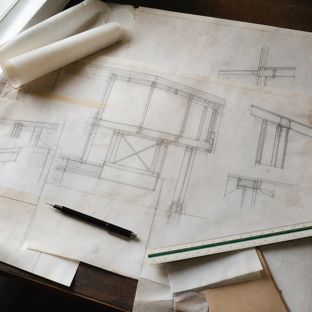
Parapet walls on low-slope residential roofs in Alberta present a suite of architectural and structural challenges, each governed by the requirements and nuances of the 2019 and 2023 Alberta Building Code (NBC(AE)), regional interpretations, and the critically high expectations of local plan reviewers, builders, and building inspectors. In the construction drawing set, these complexities surface as dense call-outs, precisely dimensioned sections, inter-sheet references, and a layering of annotated assemblies designed for rigorous review and field execution.
ABC Part 9 & NBCC 2015/2019 Alberta Parapet Framing and Compliance Annotation
Prescriptive Framing Requirements in Drawings
Parapet walls on low-slope residential roofs in Alberta must exceed mere aesthetics; their construction and specification are grounded in NBC(AE) 2019 Part 9’s prescriptive requirements. Section 9.20.6.5 states, “Except as permitted in Sentence (2), parapet walls shall be solid masonry.” In hollow or semi-solid masonry, “cells shall be filled with mortar, grout, or concrete to a depth not less than 300 mm below the adjacent roof level.” As a result, architectural sheets for projects utilizing masonry parapets typically show section views (e.g., Detail 2/A501) with shaded wall hatching, fill notes like “fill all cells solid min. 300mm below roof per 9.20.6.5,” and bold linework making clear where the parapet ends and the backup wall below begins.
Wood-framed parapets, prevalent in residential uses, require neither unreinforced height nor inboard support be left to chance. Wall studs, double top plates, and solid blocking must be indicated with explicit spacing (“38x140mm SPF @ 400mm O.C.”) and connection notes taken from the code or engineered schedules. Prescriptive roof-to-parapet anchorage, where used, requires both anchorage schedule and top-block reinforcing to be cross-referenced by detail (e.g., “see Detail 5/A302 for parapet anchorage and top plate reinforcing”).
Fire Separation Callouts (Section 9.10) for Parapets
Fire separation features and continuity dominate parapet design. Section 9.10.11.1 requires, “Party walls on a property line separating buildings or compartments shall be constructed as firewalls.” Parapet fire separation must not only rise above the finished roofline, but remain continuous and unbroken by cavities or material changes at the parapet/roof interface (Section 9.10.9.2). Drawing sheets use boxed plan notes such as: “Fire separation per ABC 9.10.11.1 to extend parapet 300mm above adjacent roof-1hr min. FRR, continuous to exterior face.” Redlines from reviewers often highlight any interruption, e.g., “Fire wall at parapet stops at roof deck-revise to maintain continuous fire rating above roof per 9.10.9.2 and 9.10.11.1.” Details must annotate all material transitions, with “Type X gypsum, both sides, continuous to exterior” and “mineral wool batt at cavity” emphasized in large type.
Energy Code Performance Details (Section 9.36) and Notes
Section 9.36 of NBC(AE) 2019 mandates minimum effective R-values for wall and roof assemblies, with strong attention to continuity at parapet/roof interfaces. “Thermal performance of parapet wall to match effective R-value of exterior wall per 9.36.” is the typical specification in detail tags. Enlarged roof-wall sections (e.g., 1/A303) reveal extruded insulation (“50mm min. Rigid XPS, extend vertically min. 300mm above roof”) wrapping continuously behind the parapet finish and linking directly to the roof insulation plane. Air barrier continuity, a frequent plan review concern, is highlighted with dashed lines and leader notes, such as “self-adhered membrane-fully lapped and sealed, continuous over parapet connection.”
Material Specifications: Dimensions and Ratings
- Minimum Height: 300mm above finished roof for fire-rated parapets, as dictated by Section 9.10.
- Fire-Resistance Rating: 1 hour or more (per project FRR schedule, continuous through parapet height).
- Insulation: Effective R-values per 9.36, typically minimum R-20 effective, with “continuous” notation at all intersections.
- Masonry Walls: “Solid fill all masonry cells to 300mm below roof per 9.20.6.5,” bolded on plans and checked during review for completeness.
Plan-Review Trends and Sheet Conventions
Reviewers frequently comment on interruptions in fire separation, incomplete or unclear insulation continuity, and ambiguous height annotation. Sheet conventions require parapet call-outs in plan, elevation, and section, with italic redtext for review comments such as “Clarify gypsum board continuity for fire rating.” Construction notes on plan sheets always cross-reference details (“see 3/A501”) and include code section references right in the note for reviewer transparency.
Structural Connection Detailing: Wind Uplift, Lateral Loads, and Anchorage
Engineered Connections: Translating Calculations into Drawings
Parapet walls above Alberta’s low-slope roofs are highly vulnerable to wind uplift and lateral wind loads-a risk not lost on the province’s building officials. NBC(AE) 2019, Section 4.1.8.1 mandates that “Design wind loadings for building surfaces shall be determined using reference velocity pressure, exposure, and gust effect factors.” Engineered design calculations, typically by a professional engineer, specify uplift and lateral design values along with minimum connection types, but it is the drafter who must convert numbers into call-outs intelligible on the shop floor and to the building inspector. “Hold-down connector, Simpson HDU2 or equivalent, installed per manufacturer, at ends of each parapet stud” and “16ga galvanized steel strap, min. 38mm width, anchored to each stud and roof joist below with (4) #10 screws” are standard plan notes derived from engineer’s schedules.
Anchorage must be direct and mapped in detail sections, with plan notes such as “anchor parapet bottom plate with ½"Ø x 127mm galv. anchor bolts @ 600mm O.C.-see S401 for additional reinforcement.” Where wood framing meets a wood deck, continuous blocking and metal strapping create the uplift-resisting path called for in Section 9.23.6, highlighted on sheets with arrows marking the “load path” and bubble notes referencing “S502/Detail 7: Parapet hold-down and tie-in.”
Sheet Call-Outs and Connection Conventions
- Anchor Bolts: “12.7mm Ø galvanized anchor bolts @ 600mm O.C.,” with bolt schedule shown in both architectural and structural details; extended by note to “locate within 150mm of plate ends.”
- Hold-Downs: “Simpson Strong-Tie HDU4 or equal at each parapet end and at 1.2m max. spacing,” dimensioned in section and plan.
- Top Plate Reinforcement: “Double top plate, 38mm lap joint min. 600mm at corners, (2) rows 3.5" spiral nails @ 300mm O.C.”
- Stud-to-Roof Framing: “Connect stud to roof blocking w/ (4) #10 screws and 16ga steel strap across intersection.”
Redline Comments and Plan-Review Focus
Frequent reviewer responses include: “No uplift prevention shown for parapet-show continuous strapping to roof joists,” or, “Ambiguous stud-to-block connection at roof-clarify with detail and spec bolt size/grade.” Experienced drafters explicitly cross-reference structural details (“see S602, Detail 2”) to ensure inspection does not catch ambiguities missed at the plan desk. All wind connection hardware is listed in hardware schedules with material, grade, manufacturer, and finish.
Dimensions and Material Specifications
- Anchor bolts: 12.7mm dia. x 127mm long min., at 600mm O.C. max spacing per engineered schedule.
- Strapping: 16ga galvanized, 38mm wide minimum, full span over parapet/roof junction.
- Hold-down devices: To match uplift values from calculations, often exceeding 1.5kN/unit, with clear plan note: “Fastener and connector schedule per S401.”
- Top Plate: (2) 38x140mm SPF, nailed at laps, with “no butt joint within 600mm of corner.”
Framing, Blocking & Waterproofing: Roof Membrane Termination and Coping/Fascia Integration
Framing for Roof Membrane Termination
Roof membrane performance at the parapet wall interface is a quintessential issue driving both waterproofing inspection failures and warranty callbacks. Code and best practice require the membrane to turn vertically up the parapet a minimum of 200mm (8")-or 300mm (12") in deep snow zones-above the finished roof per NRCA/RCABC guidance. Details such as “SBS membrane to extend min. 300mm vertically up to parapet blocking, fully adhered and mechanically terminated, see Detail 3/A504” are standard; the membrane’s top edge must be mechanically clamped and overflashed by coping.
Sections denote cant strip installation “at deck/parapet intersection, 75-100mm (3-4") base” fabricated from beveled pressure-treated 2x lumber, typically specified as “PT 38x89mm beveled cant strip.” Blocking for membrane term and coping receives explicit annotation for size, fastener type, and preservative treatment, as in: “Install PT 2x6 continuous blocking at parapet top, fasten with (2) 89mm galvanized framing screws @ 400mm O.C., staggered.”
Coping Attachment and Finish Detailing
Coping-whether metal, membrane, or stone-requires sloped installation (min. 1/4" per ft or 2%) toward the interior roof, a common redline when omitted. Standard detail note: “Pre-formed metal coping, 1.0mm galv. steel, hemmed edge, sloped min. 2% toward roof, extend min. 25mm past exterior face, drip hem required, see 4/A504.” Fasteners are detailed as “concealed anchor clips @ 600mm O.C., finish pop-rivet in returns,” with cross-references to both architectural and sheet metal schedules.
Through-Wall Flashing and Drainage
Masonry parapets demand through-wall flashing to prevent interior moisture ingress-a repeated ABA code review concern. Assemblies are drawn with a horizontal flashing line “through full wall thickness, lapped min. 150mm at joints, with weep holes @ 600mm O.C. full length.” Flashing materials-metal, peel-and-stick membrane-are labeled with manufacturers and thicknesses. Reviewer redlines commonly note, “Through-wall flashing not continuous-add section and keynote for weeps per 9.26.4.”
Blocking, Cant, and Integration Details
- Membrane Extension: 200mm (min.), 300mm in snow zones, above finished roof.
- Coping: 25mm overhang minimum, 2% slope inboard, hemmed drip required.
- Blocking Lumber: PT 2x4 or 2x6, “Install continuous, fasten both sides” notes.
- Cant Strip: “PT triangle, 75x75mm. Secure with (2) 89mm galv. screws @ 600mm O.C.”
- Fasteners: All exterior/roof fasteners “hot-dip galvanized or stainless in weather-exposed applications.”
Common Reviewer Comments and Redlines
- “Roof membrane detail fails to show vertical extension beyond cant. Revise for 8" min. height at parapet per industry/hazard zone.”
- “Coping detail does not include positive slope; add dimension and note for 2% minimum inward slope.”
- “Weep hole spacing for through-wall flashing not specified or dimensioned; add 24" O.C. to plan note.”
- “Block dimension/fastening not specified as PT. Revise to indicate PT for all exposed/blocking at parapet.”
Plan-Set Sheet Organization, Dimensioning Standards, & Annotation Protocols
Location, Layering, and Sheet Numbering
In Alberta architectural plan sets, parapet walls are typically detailed on “A500-series” sheets (“A501-Architectural Details,” “A503-Enlarged Roof Details”), with key section and isometric details located immediately following or adjacent to roof plans and exterior elevations. Blown-up sections (“1/A501: Parapet at roof corner; 2/A501: Parapet control joint”) zoom on critical interfaces. Structural tie-ins and load path elements appear on “S” sheet equivalents (“S503-Framing Connections at Roof Parapet”). Sheet index includes explicit cross-references (“see A504 for coping flashing details; see S602 for wind anchorage schedule”).
Dimensioning Sequences and Material Annotation Standards
Parapet details deploy both vertical (height above finished roof/deck, membrane height, coping thickness) and horizontal (parapet width, overhang, wall thickness) dimensions. Dimension chains begin at structural deck and run upward-to bottom of parapet, membrane term, finish grade-as “300mm PARAPET HGT. ABOVE ROOF (ABC 9.10),” “150mm membrane upstand,” “PT 2x6 BLOCKING (38x140mm),” all in bold for code/dimension compliance. Noting conventions require all sizes and thickness in Canadian metric (“38x140 SPF,” “1.5mm prefinished steel”). Material tags (clouded or boxed) directly key to a “Materials Schedule” table nearby.
Keynoting and Cross-Referencing within and between Disciplines
- Keynotes: Numbered and/or lettered tags match schedule: “K1-Self-adhered membrane, 1.5mm, fully lapped”); “K2-Prefinished galv. steel coping.”
- Detail Referencing: Bubble callouts (“see 2/A504”) index to enlarged or 3D details. Tagging must be consistent: if “Detail 1/A501: Parapet Cap”; all related references use the same number.
- Coordination Notes: Where architectural and structural elements overlap, notes state, “Coordinate with S503 for anchorage,” or “See S602 for tie-down schedule.”
Common Plan-Review Redlines
- “Flashing position ambiguous-move section reference to indicate location over wall sheathing.”
- “Air barrier continuity not shown at parapet transition-add dashed line/symbol per Part 5 convention.”
- “Scale missing on parapet detail-show ‘1:5’ in title bar.”
- “No material tags for coping or membrane-add call-outs and cross-ref. to materials schedule.”
Integrating Expansion/Control Joints and Fire-Stopping in Parapets
Expansion/Control Joint Placement, Framing and Detailing
Alberta climate throws large temperature swings at rooftops, making control/expansion joints essential for long parapet runs and material transitions. Joint spacing is typically 6-9m (20-30 feet) in masonry, referenced in plan grids: “Provide expansion joint at grid lines 3/6-coordinate with control joint in wall below.” In wood-framed parapets, details (“4/A502: Parapet Expansion Joint”) call for “gap min. 12mm-25mm, filled with compressible backer rod and sealed with fire-rated intumescent caulk.” Blocking is interrupted and capped at joints, with both sides tied to structural framing using slotted steel plate connectors (to allow for movement), noted as, “16ga galvanized slip plate at joint, attach each side with (3) #10 screws-no positive fastener through joint.”
Fire-Blocking, Draft Stops, and Fire-Rated Assemblies
Firestopping requirements in parapets stem from NBC(AE) Article 3.1.10.2, with “fire separations, including all joints, must maintain specified ratings through roof and wall transitions.” Sectional and plan details annotate “mineral wool fire-block at parapet/roof joint-install continuous through cavity, fully sealed, see Detail 5/A503.” At firewalls, Article 3.1.10.4 requires that “the parapet must extend not less than 150 mm above the roof surface where a firewall is required to have a 2-hr fire resistance rating,” shown on plans as “Parapet/Firewall Elevation-ABC 3.1.10.4, min. 150mm height above membrane.” Material call-outs include “Type C gypsum x2 layers, both sides parapet, continuous,” and “firestop caulk, red, rated, at all transitions.” Control joints within fire-rated parapets require by-code tested fire barrier assemblies, so details list UL or cUL assembly references, such as “Fire barrier assembly: see UL WJ1077 for joint firestopping at expansion channel.”
Sheet Call-Outs, Dimensions and Material Tags
- Expansion Joint Width: 12-25mm gap, backer rod and intumescent sealant, “gap must not be bridged by continuous blocking.”
- Fire-Resistance Rating: “Parapet FRR as wall/firewall below, not less than 2 hrs where firewall required, continuous through roof.”
- Fire-Blocking Material: “Mineral wool batt, FSK faced, continuous,” or “2 x 16mm Type X gypsum.”
- Inspections/Redlines: “Move firestop to cavity midpoint for continuity,” “Verify non-combustible construction through full parapet height.”
- Detail Referencing: Bubble “see 6/A503 for typical fire separation at parapet/roof.”
Typical Reviewer Comments
- “Expansion/control joints lack firestopping-add tested assembly and detail at all joint locations.”
- “Parapet at firewall not shown with full-height FRR-reference 3.1.10.4 and coordinate S/Arch.”
- “Fire block detail unclear-add section and clarifying material call-out.”
Alberta Code References and Assembly Conventions
- Firewalls per ABC 3.1.10.4: “Extend minimum 150mm above roof for 2hr FRR firewall.”
- Fire Separation per 9.10.11.1: “Party wall to continue through parapet.”
- Exp. Joint Assemblies: UL or cUL listed, “must maintain fire resistance at joint per code.”
Summary: Code-Driven Parapet Documentation and Detailing for Construction
Effective parapet wall detailing on Alberta low-slope residential roofs distills code into layered, dimensioned, and highly cross-referenced plansheets, blending fire, wind, energy, and waterproofing requirements. The construction documents bear the cumulative force of prescriptive standards: Section 9.20.6.5 calls out solid fill to 300mm, Sections 9.10.11.1 and 3.1.10.4 dictate continuous fire separation and minimum heights, Section 9.36 enforces R-value continuity, and both wind (4.1.8.1) and anchorage (9.23.6) stress repeatable, dimensioned structural ties. Reviewer redlines and approvals alike hinge on clarity of detail tags, scale, material specification, referenced code sections, and explicit connection to engineer directives across the architectural (“A”) and structural (“S”) drawing sets.
By weaving these drawing and specification conventions into plan documentation, drafters and design teams provide the surest roadmap for successful permit review and durable on-site performance-no parapet left behind.
Kingsway Drafting & Design sets the benchmark for Alberta drafting practices, ensuring every plan sheet for parapet wall assemblies is both code-exact and constructible in the field.