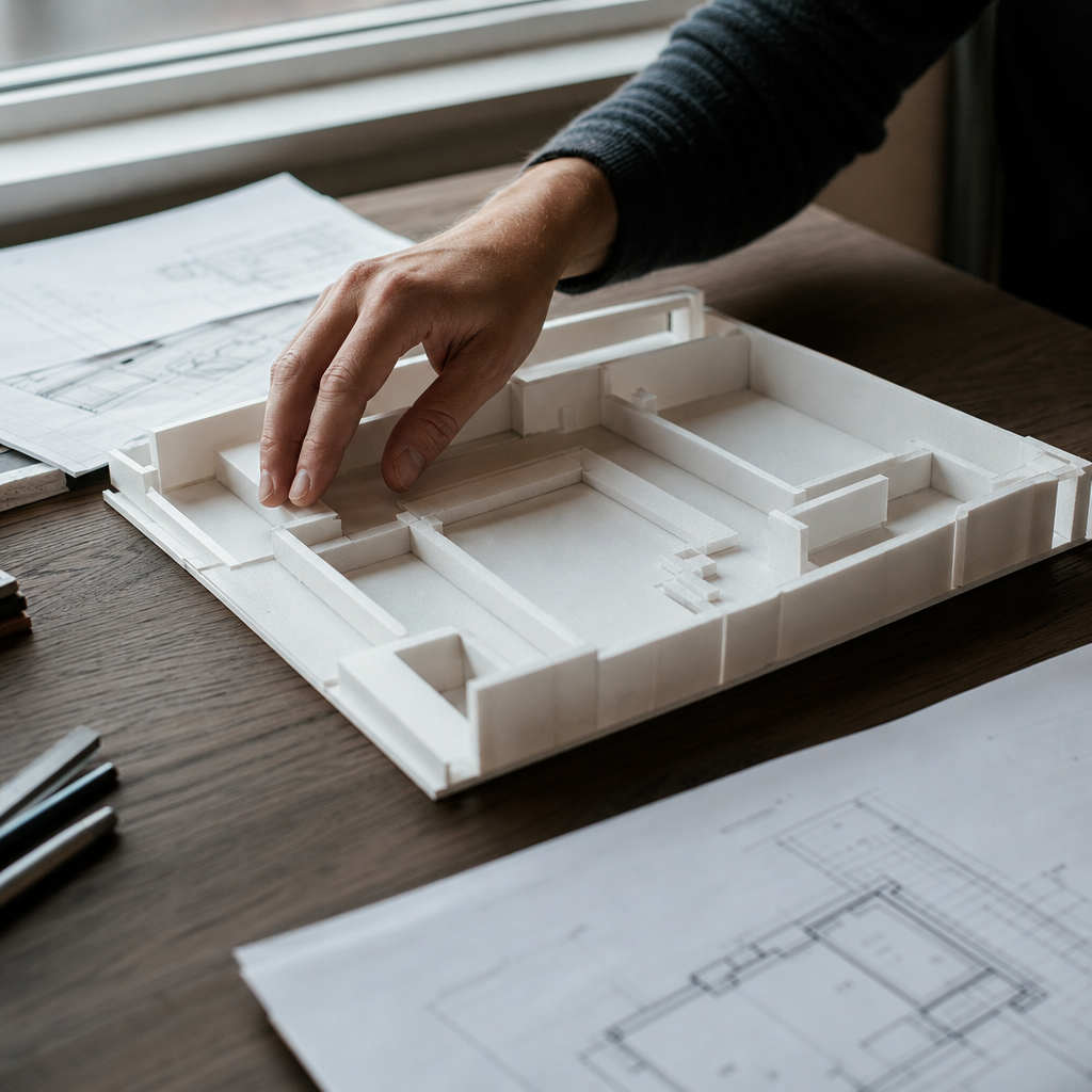
Slab depressions and recesses for floor finish transitions in Alberta basements are governed by tightly defined parameters in the National Building Code - 2023 Alberta Edition (NBC(AE)) and by best practice construction detailing. Accurate drawing annotations, dimensioning strategies, reinforcement and formwork conventions, MEP coordination, and plan-review readiness are all non-optional if clearances, accessibility, finish levels, and inspection approvals are to be achieved without friction. Modern floor assemblies-from tile to luxury vinyl plank-make slab depressions routine, but never trivial: a few missing millimeters or an ambiguous note can disrupt the entire finish and expose projects to costly rework. Basements in particular, with their low head clearances and integration of below-slab systems, demand even higher scrutiny.
ABC-Compliant Specification and Drawing Annotations for Slab Depression Depths
Minimum Floor-to-Ceiling Heights in NBC(AE) Section 9.5.3.1
Determining slab depression depths begins by referencing Alberta’s mandatory minimum floor-to-finished-ceiling heights. NBC(AE) 2023 Section 9.5.3.1 mandates:
- 2.1 m (6'11") for habitable rooms (living, sleeping, or recreation), measured on the finished floor after all floor finishes are installed, over the lesser of the whole room or its code-required minimum area (e.g., 10.0 m² for living rooms).
- 2.0 m (6'7") for unfinished basements or under beams/ducts in passage zones; 2.1 m for finished basements throughout.
Any slab depression must account for not only the finish thickness but also the remaining available headroom post-installation. A depression that encroaches on the code minimum exposes the entire finished space to non-compliance at inspection-even if it is limited to a small footprint.
To prevent this, the following general note often appears on working drawings:
“ALL SLAB DEPRESSIONS TO ACCOMMODATE FINISH MATERIALS AS SPECIFIED. VERIFY FINAL FLOOR ELEVATIONS TO MAINTAIN MINIMUM CEILING HEIGHTS PER NBC(AE) 9.5.3.1.”
Step Changes and Accessibility: NBC(AE) Section 3.8.3.3
Slab depressions designed to create finish recesses must also comply with NBC(AE) Section 3.8.3.3, which addresses interior ramps and floor level changes. The code clearly prohibits abrupt changes in floor elevation exceeding 200 mm (7 7/8") unless addressed by a ramp or lift. While most finish-related slab depressions are much less dramatic, those for showers or built-in sunken zones must have precise documentation:
- “MAXIMUM FLOOR LEVEL CHANGE WITHIN A STOREY NOT TO EXCEED 200 mm UNLESS OTHERWISE NOTED AND DETAILED WITH RAMP/LIFT, PER NBC(AE) 3.8.3.3.”
Calculating Slab Depression Depth: Material Build-Up References
Each finish assembly should be decomposed into its full material thickness at the drawing stage. For example:
- Standard Tile Over Mortar: 10 mm porcelain tile + 28 mm reinforced mortar bed = 38 mm total build-up
- Luxury Vinyl Plank (LVP): 5 mm LVP + 3 mm foam underlayment = 8 mm total build-up
- Laminate with OSB Underlay: 8 mm laminate + 11 mm OSB + 3 mm underlay = 22 mm total build-up
This prompts explicit plan annotations, which may read:
- “SLAB DEPRESSION -38 mm AFF FOR 10 mm TILE + 28 mm MORTAR”
- “SLAB DEPRESSION -8 mm AFF FOR 5 mm LVP + 3 mm UNDERLAY”
The intent is to communicate unambiguously to every cross-disciplinary site actor-including concrete crew, inspectors, and flooring trades-the expected finish level relationship.
Exact Drawing Note Examples with Code Call-Outs and Redline Prevention
- On plans: “PROVIDE SLAB DEPRESSION AS SCHEDULED; RE: S101/Detail 3 FOR DEPTHS AND FINISH BUILD-UP. COORDINATE TO MAINTAIN 2.1 m CEILING HEIGHT, SEE NBC(AE) 9.5.3.1.”
Common review comments:
- “Insufficient detail-specify all finish materials and exact slab depression depths. Confirm post-finish floor-to-ceiling dimensions.”
- “Step depth exceeds 200 mm-adjust for accessibility or provide ramp detail as per 3.8.3.3.”
Explicitly annotating slab depressions and cross-referencing with assembly schedules yields clear builds and smooth approvals, sparing weeks of lost time to submittal rejections or field changes.
Code Reference Quick Sheet
- Ceiling heights: NBC(AE) 9.5.3.1
- Accessibility/steps: NBC(AE) 3.8.3.3
- Local STANDATA: Always verify interpretations or new variances via alberta.ca/building-standata
Dimensioning and Graphical Representation of Slab Depressions in Working Drawings
Precise Dimensioning Conventions and Datum Control
Plans must dimension slab depression perimeters, locations, and extents relative to non-negotiable building fixed points-foundation walls, gridlines, framing centers. An effective strategy uses:
- Continuous dimension strings from wall face or gridline: “DEPRESSION EXTENDS 1200 mm FROM NORTH FOUNDATION WALL”
- Dimension to clear, easily established site objects; never to “foam line” or “approximate slab edge” due to placement tolerance issues.
Insufficient or ambiguous depression extent is a top plan-review redline:
- “Slab depression boundaries not dimensioned to fixed references. Revise for field layout.”
Graphical Methods: Line Weight, Hatching, Elevations, and Markers
Typical representation protocol includes:
- Heavy lineweight (solid): depression perimeter
- Distinct hatch pattern (dense crosshatch or diagonal): within depressed area, as assigned in the drawing legend
- Spot elevation markers: shown at each corner and at any inflection (e.g., “-38 mm AFF”, or related to project datum, e.g., “+100.000 m” main slab, “+99.962 m” depression)
- Elevation datum call-outs for all slab transitions: “TOP OF ADJACENT SLAB = DATUM”; all spot elevations in reference to that datum.
Section Markers and Match-Lines
Sections through depressions are referenced directly from the plan using consistent markers:
- “SEE DETAIL 2/S-103 AT ALL SLAB DEPRESSION EDGES”
This guides field crews directly to all necessary information for step edge forming and reinforcement details.
Concrete Placement Tolerances and Acceptance Criteria (CSA A23.1)
Depressions are rarely achieved to absolute millimeter precision post-placement; allowance for slab thickness and base elevation tolerance is critical. Per CSA A23.1:
- Thickness tolerance: average thickness not more than 10 mm less than specified; no individual location more than 20 mm less than specified.
- Granular base elevation: variation not to exceed ±10 mm.
Drawings must translate these tolerances into field instructions and specify acceptable range for finish, flagging any tolerance-critical locations in the general notes:
- “SLAB DEPRESSION +0/-10 mm FROM DESIGN DEPTH; CONTRACTOR TO COORDINATE WITH FINISH INSTALLER.”
Redlines from Lack of Graphical Clarity
- “Hatch pattern unclear in depressed area; revise legend and shading for clarity.”
- “Spot elevation missing at depression edge-cannot confirm depth at transition.”
Sophisticated graphical conventions and disciplined dimensioning both remove layout guesswork and satisfy review scrutiny.
Reinforcement Detailing and Formwork for Depressed Slab Transitions
Maintaining Reinforcement Continuity at Step Edges (CSA A23.3)
Intact load transfer and crack control at elevation changes depends on proper rebar anchorage, bends, and laps:
- Bent rebar: Main slab reinforcement often needs a 90° downward leg extending into the depression, conforming to minimum bend diameter per CSA A23.3.
- Lap lengths: Laps must meet minimum values to develop full strength; for Grade 400 rebar, typical minimum lap is 600 mm for 10M bar per CSA A23.3, Table 12.
- Clear cover: At step edges and transitions, minimum 75 mm clear cover for slab-on-ground per CSA A23.1-19, Clause 6.6.6.2.
Section details should show:
- Bar size and spacing (e.g., “10M @ 200 mm O.C. E.W.”)
- Bends terminating within the depression with proper cover
- Splices/laps clearly dimensioned and labeled
Formwork Material and Method Call-Outs at Step Transitions (CSA S269.1)
Clean, square edges at depressions are only achieved with purpose-built, secured, and braced formwork.
- Standard note: “PROVIDE 2x4 FORMWORK, SECURELY BRACED TO ACHIEVE TRUE EDGE ALIGNMENT AT SLAB DEPRESSIONS. STRIP AFTER CONCRETE SETS.”
- Materials for exposed edges: 18 mm (3/4") plywood supported at 400 mm O.C. max for sharp lines.
- Refer to CSA S269.1 for additional design, fabrication, and erection procedures.
Vapour Barrier/Membrane Transitions and Detailing
Beneath any slab depression, vapour barrier continuity is required to prevent moisture intrusion:
- Lap all vapour barrier seams minimum 150 mm and seal with compatible tape/adhesive.
- Show barriers running continuous across step transitions, clearly toed into both main and depressed slab areas on sections.
- “CONTINUOUS 6-MIL POLYETHYLENE VAPOUR BARRIER UNDER ALL SLAB AREAS INCLUDING DEPRESSIONS; LAPS 150 mm MIN, SEALED.”
Redlines for membrane discontinuities are common:
- “Vapour barrier break at depression-not shown continuous. Revise detail.”
Concrete Strength, Bar Grade, and Other Material Specifications
Standard Alberta slab depression details will reference:
- Concrete: 30 MPa at 28 days (residential), higher strength possible for garages/commercial
- Reinforcement: CSA G30.18, Grade 400, detailed size and spacing
- Formwork: 18 mm plywood, 2x4 dimensional lumber as brace, suitable release agent for clean stripping
Comprehensive section and detail call-outs prevent ambiguity at field execution and passing inspection.
MEP Integration in Slab Depressions: Drawing and Coordination Tactics
Plumbing Rough-Ins: Section 9.31.4.4 and Coordination Detailing
Slab depressions nearly always coordinate with plumbing elements-floor drains, shower sumps, and pipe penetrations. Drawings must:
- Show sleeves/blockouts for all pipe penetrations, dimensioned to finished wall face or column grid
- Indicate required slab thickening or added rebar mats around large penetrations to maintain load path continuity
- Add keynotes such as “PROVIDE 100 mm PVC SLEEVE FOR FUTURE DRAIN LINE, RE: PLUMBING DWGS”
Plan reviewers frequent comment on missing/ambiguous information:
- “Plumbing penetration not located/dimensioned within depression-risk of conflict with slab rebar. Revise.”
Radiant Floor Heating: PEX Tubing Layouts and Below-Slab Insulation
Radiant floor systems raise coordination stakes further. NBC(AE) and STANDATA Variance 19-BCV-005 require:
- Insulation under heated slabs: Rigid insulation minimum R-10 under heated depression zones; note “PROVIDE 50 mm TYPE II EPS UNDER DEPRESSION PER STANDATA 19-BCV-005”.
- PEX Clearances: Ensure minimum 50 mm (2") concrete cover over PEX (CSA B214 residential hydronic standards). Tubing must avoid slab edge at depressions-detail on mechanical/structural overlay.
- Blockouts for manifolds or stub-ups: Show on both plan and section, with call-outs referencing plumbing/MEP set.
Typical plan keynotes:
- “16 mm PEX @ 300 mm O.C., 50 mm MIN. CONCRETE COVER. AVOID CROSSING DEPRESSION TRANSITIONS; REFER TO MECH DWGS.”
Electrical Conduit and Floor Boxes: Canadian Electrical Code in Slabs
Electrical elements must also be coordinated at the drawing stage:
- Conduit sleeves: Show location and size in plan, with exact stub-up position and elevation-"PROVIDE 25 mm EMT SLEEVE, MIN. 50 mm COVER TO TOP OF CONDUIT, RE: ELEC DWGS."
- Blockouts for floor boxes: Drawings and general notes must define slab thickening or rebar crossings at electrical box locations.
Common redlines/review comments:
- “Electrical sleeve detail not coordinated with slab depression reinforcement, revise for adequate cover and clearances.”
Coordinated Overlay and Clash Detection Drawings
Project teams increasingly demand BIM overlays or at minimum MEP/structural plan overlays to avoid in-field conflicts. Clear layering, hatching, color-coding, and precise spot elevation markers highlight all MEP penetrations and below-slab features within depressions, with cross-reference notes to each engineering discipline’s drawing set.
Preventing Common Plan Review Redlines and Field RFIs for Slab Depressions
Catalog of Frequent Plan Review Redlines (NBC(AE), Engineering Reviewers)
- Missing level indications: “Provide finished floor elevations for all slab depressions; reference NBC(AE) 3.2.1.1.”
Best practice: Spot elevations at every corner, referenced to established project datum. - Unclear extents: “Define the horizontal extents of slab depressions on plan; see NBC(AE) 3.2.2.2.”
Best practice: Dimension strings from fixed elements, perimeter highlighted with distinctive hatch. - Insufficient structural detail: “Detail reinforcement for slab depressions to prevent cracking; refer to NBC(AE) 4.3.3.1.”
Best practice: Provide sections showing edge details, bar bends/laps, and step edge thickening. - Finish build-up conflict: “Slab depression too shallow for specified finish system-clarify assembly and adjust depth.”
Best practice: Tie all depression depths to finish schedules; include general note instructing adjustment per final selection with minimum code height reserved.
Examples of Jobsite RFIs Prompted by Drawing Ambiguity
Common site questions flowing from incomplete or vague drawings:
- Incorrect pour depths: “RFI-102: Level 1, Grid B3 - Confirm correct pour depth for slab depression; current drawings indicate 100 mm, but site conditions suggest 150 mm.”
- Rebar interference: “RFI-205: Level 2, Grid D5 - Rebar layout in slab depression conflicts with mechanical penetrations; request revised detail.”
- Finish material conflict: “RFI-310: Level 3, Grid F7 - Slab depression depth insufficient for specified tile assembly; advise on adjustment.”
Best Practices for Supplemental Instructions and Revision Annotations
- Supplemental instruction clarity: Use precise language and always cross-reference affected plan, section, or detail number. Pair with diagrammatic markups.
- Revision clouds: Encircle all changes. Assign unique revision number and date. "Rev. 3-Slab Depressions by main entry deepened to -38 mm, see S101-4".
- Legend updates: Update all drawing-legend descriptors for new or clarified hatch patterns and symbols; avoid any informal or ambiguous marks that may confuse subtrades or scrutineers.
Standard Call-Outs and Material Specs by Alberta Practice
- Depression thickness: Minimum 100 mm for residential (slab-on-grade or basement); increase as required for load or where penetrated by numerous services.
- Reinforcement: 10M bar at 300 mm O.C. (each way), or as per structural; critical at depression perimeter and any thickened zones for mechanical/electrical blockouts.
- Thermal/vapour protection: R-10 rigid insulation for heated slabs, continuous 6-mil poly vapour barrier lapped and sealed.
- Finish notes: “INSTALL FINISH PER MANUFACTURER SPEC. COORDINATE WITH DEPRESSION DEPTH TO ENSURE FLUSH OR INTENDED RECESSED FINISH.”
Schematic Layout for Most Common Issues
- Plan View: Heavy linework per depression, hatch fill, multiple clear dimensions to structural grid, labeled spot elevations at all depression corners, clear tie-ins to adjacent assemblies.
- Section View: Full layering (slab, insulation, vapour barrier, finish assembly), bar top/bottom, dimensioned height from top of main slab to depression base, and explanatory finish call-outs.
This level of explicitness not only solves code compliance, but also prevents “workarounds” and re-pours by site crews.
Conclusion
Every slab depression or recess in Alberta basement construction is controlled by code thresholds, physical tolerances, and the demand for buildable, inspection-ready detail. Projects succeed or fail at these transitions based on the drafter’s discipline in annotation, dimensioning, reinforcement layout, MEP coordination, and responsiveness to review redlines and site queries. Industry-standard practices-backed by Section 9.5.3.1 for ceiling heights, Section 3.8.3.3 for accessibility, and technical specifications from CSA and local STANDATA bulletins-prevent the most frequent, costly issues. Unambiguous drawings, clear material build-up notes, and coordinated supplementals eliminate ambiguity and uphold both code and site realities. For Alberta projects, rigorous documentation of slab depressions delivers not just finishes that align-but entire buildings that pass on the first inspection.
Kingsway Drafting & Design delivers code-compliant, detail-driven architectural drafting for residential construction throughout Calgary and Alberta.