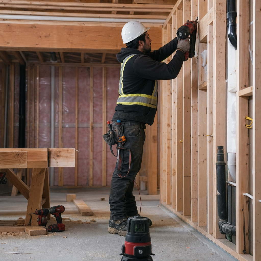
Future basement development potential profoundly shapes the information presented on Alberta residential plan sheets. Code-compliant rough-ins, structural backing, and explicit drawing conventions form the backbone of well-documented, future-ready homes. On project sites across Calgary and Alberta, careful dimensioning, deliberate material call-outs, and inter-discipline coordination ensure that future work-plumbing, electrical, HVAC, and finish-ready backing-can be executed without code violations, demolition, or inspection failures. From DWV provisions appearing as dashed lines on foundation plans to blocking for bathroom grab bars detailed on wall-framing sheets, every provision must stand the scrutiny of both the Alberta Building Code (ABC 2019, NBC(AE) 2023) and the rigorous redline of plan reviewers. The resulting set of contract documents is not merely an instruction manual for present construction, but a code-mandated roadmap for tomorrow’s value-adding improvements.
Drafting & Code Compliance for Future Plumbing DWV Rough-Ins
Dimensioning, Notation, and Fixture Unit Schedules on Foundation Plans
Future plumbing drainage, waste, and vent (DWV) rough-ins must be precisely located and identified on foundation plan sheets. On Alberta permit sets, DWV rough-in stubs for future bathrooms, kitchens, or suites are most often shown with standardized plumbing symbols (per CSA standards), keyed with fixture call-outs and annotated as "FUTURE 3PC BATH ROUGH-IN" or similar. In accordance with the Alberta Building Code (ABC) Part 7, drafters must include:
- Fixture Unit Schedules: Table or schedule indicating the anticipated fixture unit (DFU) loads for each future connection. For example, for a full bath rough-in: "Future Bathroom Group (Toilet, Lav, Bath): 6 DFUs. Pipe Size: 3” min. as per ABC 7.4.9.2(2)".
- Pipe Size & Slope Notation: "3ӯ PVC @ 2% MIN. SLOPE (1:50) TYP. PER ABC 7.4.9.2, 7.4.10.1"
- Trap Arm & Vent Notation: "ALL TRAP ARMS TO MEET MAX LENGTHS PER ABC Table 7.5.6.3 - 1¼” trap arm max 1.5m (5ft), min slope 2%".
- Future Fixture Outlets: Clearly marked stub-out locations (dashed lines), labeled by type-e.g. "FUTURE LAV. 1½”Ø OUTLET", "FUTURE WC 3”Ø STUB, VENTED".
Precise centreline dimensions from foundation walls or structural grids are required for all future rough-in points, typically called out as "X mm from inside face of West foundation wall" and "Y mm from nearest gridline", ensuring future framing aligns with rough-in locations.
Code Requirements: Pipe Sizing, Slope, and Future Connections (ABC Part 7)
- Per ABC 7.4.9.2(2): "A water closet shall be served by a 3 in. (75 mm) min. drain and branch... If three or more water closets are connected, the building drain downstream shall be 4 in. (100 mm) min."
- Bathe outlets and vent stubs: "1½” min. for tub/shower, 1¼” for lavatory, all at min. 1:50 slope."
- Cleanout locations: "ABC 7.4.7.1(1) - A cleanout shall be provided at the base of every waste stack and at each change of direction exceeding 45 degrees."
- Trap seal retention: "Trap arm lengths shall not be exceeded; see ABC Table 7.5.6.3. Minimum vent connections via vent stack to atmosphere shall be called out for each fixture group."
- "Future connections": Provide capped (accessible) wyes or sanitary tees as connection points, annotated as "FUTURE 3” WYE W/ SCREW CAP-LOCATED FLUSH W/ SLAB, ACCESSIBLE POST-DEVELOPMENT".
Slab Depressions and Structural Coordination
Foundation plans must contour slab depressions for future showers or bathtubs, with explicit dimensions and cross-references to structural sheets. A typical call-out: "100mm slab depression for future shower, ref. Struct. Dtl 2/S4.1." Plan notes must ensure this does not compromise slab bearing or load-transferring elements. Coordination between architectural, plumbing, and structural is flagged with coordination notes such as:
- "ARCH to coordinate all future rough-in locations and slab depressions with STRUC prior to permit issue."
Plan Review Redlines: Real Comments & Construction Issues
- "Add cleanout access per ABC 7.4.7 - none shown in future bath rough-in location."
- "Future bathroom group does not meet minimum trap venting/trap arm distance - revise notes to cite ABC Table 7.5.6.3 limits."
- "Indicate fixture unit (DFU) count and total cumulative load per branch."
- "Dimension slab depression to match anticipated shower base-specify finished grade drop and waterproofing note per ABC 9.27.3.1."
Standard Drawing Notation & Conventions
- Dashed piping lines with bolded “FUTURE” annotation for planned but-uninstalled runs.
- Call-outs such as: "FUTURE 3PC ROUGH-IN: 3”Ø WC, 1½”Ø LAV, 1½”Ø TUB WASTE, VENT TO BE EXTENDED UPON FUTURE DEVELOPMENT."
- General notes: "All plumbing rough-ins to conform with ABC 2019, Part 7. Contractor to verify in field prior to pour."
Electrical Rough-Ins & Main Panel Future-Proofing
Main Panel Sizing and Permit Overviews
Dwellings anticipating future basement finishes or suites must be drafted with main panel and service sizes reflecting potential future loads. The Canadian Electrical Code (CEC) Rule 8-200 dictates that "the minimum ampacity for a residential service is 100A; where a suite or secondary kitchen is anticipated, 200A panels are strongly recommended." This is noted on electrical sheets as:
- "100A/200A MAIN PANEL (TYP), SIZED FOR FUTURE BASEMENT DEVELOPMENT/SECONDARY SUITE. LOAD CALCS PER CEC RULE 8-200."
Electrical single-line diagrams dimension main panel height ("1.7m to centre AFF"), with future sub-panel knockouts or conduits shown and labeled as dashed lines/conduits with explicit future annotation ("FUTURE BASEMENT SUB-PANEL: 60A MAXIMUM CAPACITY, 27mm CONDUIT FROM MAIN PANEL").
Dedicated Circuits and Conduit Rough-Ins
- Kitchen: Per CEC rules, "2X 20A circuits min. for kitchen counter receptacles (CEC Rule 26-652). Future kitchen GFCIs annotated as ‘FUTURE 20A 120V GFCI, 3#12 AWG IN 19mm CONDUIT’."
- Bathroom: "Bathroom receptacle circuit to be GFCI-protected per CEC Rule 26-704. Provide blanked-out junction box and spare conduit if future full bathroom is expected."
- Laundry: "Laundry outlet: dedicated 20A min., rough-in 27mm conduit for potential future dryer if none present above slab."
Plan notes frequently specify: "INSTALL CONDUIT AND JUNCTION BOXES FOR FUTURE CIRCUITING - SEE ELECTRICAL PLAN FOR LOCATIONS" and "ALL ROUGH-INS TO EXTEND TO ACCESSIBLE LOCATION ABOVE BASEMENT CEILING FOR FUTURE PULLS." These are supported by schedules on the sheet denoting circuit numbering, dedicated uses, and breaker slot allocation for the future development.
Future Receptacle/Switch Location Representation
Future device boxes are marked with dashed device symbols ("GFCI RECEPTACLE BOX (FUTURE)" or "FUTURE 3-WAY SWITCH BOX"), corresponding to a legend. All future electrical elements use distinct line-types (dashed) and annotation, with dimensions from framing/grid for clear as-builts ("FUTURE BATH RECEPT. BOX 1050mm AFF, 600mm from West framed wall").
General notes reiterate: "Contractor to install conduit only; wiring to be installed at future suite build-out. All future boxes to be blank-plated until energized under separate permit."
Plan Review Redlines and Common Electrical Comments
- "Panel sizing inadequate for future suite load - show updated panel schedule with load calc per CEC 8-200 and future suite appliances."
- "Insufficient GFCI and AFCI protection indicated. Update plans to show all future living areas AFCI-protected (CEC 26-656); all future wet-area receptacles GFCI-protected."
- "No conduit for future kitchen/bath/laundry - add 21mm/27mm conduit runs between main and future basement areas as per Alberta STANDATA."
Drawing Sheet and Detail Conventions: Legends, Schedules, & Dimensions
- Comprehensive legend for all symbols, including dashed representations for future work apparatus.
- Panel schedules on drawing: showing "SPARE SPACES FOR FUTURE SUITE CIRCUITS, MIN. 4 SPACES RESERVED."
- Electrical conduit routings dimensioned and referenced to floor penetrations ("FUTURE CONDUIT THROUGH FLOOR SLEEVE - 75mm DIAM. CORE, ALIGN W/ STRUCT. SCHEDULES").
- "All work to conform to Alberta Electrical Utility Code, CEC 2021, and local bylaws."
HVAC Provisions for Future Basement Development
Specifying & Dimensioning Supply/Return Ducts and Provisions
Mechanical drawings must unambiguously detail future supply and return air distribution for unfinished basements. Duct drops are illustrated with dashed-line ductwork, labeled as "FUTURE SUPPLY AIR DROP LOC [300x200mm DUCT] - INSTALL CAP, VERIFY ACCESS TO MAIN TRUNK" and complete with dimensions to foundation walls or structural grids. Duct sizing aligns with calculated future loads ("FUTURE BASEMENT ZONE: 400CFM ESTIMATED, SUPPLY DUCT 300x200mm, RETURN 300x200mm, PER SMACNA MANUALS & NBC(AE) 6.2.2.1").
That plan sheet might annotate:
- "DEDUCT FUTURE SUPPLY/RETURN DUCTS FROM MAIN TRUNK AS SHOWN. LOCATE DROPS W/IN 150mm OF INDICATED GI GRID."
- "ALL FUTURE HVAC TO BE CAPPED AND SEALED PER NBC(AE) 2023 6.2.3.5 TO MAINTAIN CONT. AIR/VAPOUR BARRIER UNTIL FUTURE ACTIVATION."
Anticipated Vent Locations and Provisions for Zoning
Drafted drawings typically show anticipated supply and return vent locations, each annotated "FUTURE 4x10 GRILLE @ 200mm AFF, cf. NBCAE 6.2.2.4 VENTILATION BALANCING" and further dimensioned to structural grid or walls. For intended future zoning, plans illustrate potential damper locations and wiring routes for future thermostats, such as:
- "FUTURE BASEMENT ZONE - ALLOW FOR MOTORIZED DAMPER IN MAIN FEED, T-STAT WIRE TO RETURN TO PRIMARY MECHANICAL ROOM, RUN CONCEALED W/IN WALL CAVITY."
- "ROUTE SPARE 21mm CONDUIT FOR FUTURE T-STAT, STUB IN MECH. ROOM"
Coordination notes alert the HVAC contractor and electrician to maintain these pathways unblocked and accessible for retrofits.
Mechanical Plan Annotations for Code Compliance (NBC(AE) Part 6)
Mechanical drawings require explicit code citations and references, for example:
- "ALL HVAC ROUGH-INS TO CONFORM TO NBC(AE) 2023, PART 6. DUCTWORK AND TERMINALS TO MEET MATERIAL STANDARDS PER 3.6.5.1"
- "FUTURE HRV/ERV CONNECTION POINT PROVIDED ON MAIN RETURN AIR (SEE DETAIL 2/M4.2). SEAL UNTIL FUTURE USE; INSULATE DUCTS PER NBCAE 6.2.2.3."
Drawing notes ensure the air barrier, vapour barrier, and insulation continuity are not defeated by future rough-ins, and instruct sealing until future activation: "SEAL ALL UNUSED DUCT CAPTIVELY W/ FOIL TAPE, INSULATION SLEEVES (R8 MIN) UNTIL FUTURE OCCUPANCY."
Jobsite Coordination Challenges & Verification Points
- Structural Conflicts: Duct routing must clear beams, bearing walls, and future ceiling bulkheads; notes such as "COORD. W/ STRUCT TO MAINTAIN 25mm MIN. CLEAR TO JOIST TOP/BOTTOM FOR DUCT INSTALL" are standard.
- Space Provision: Mechanical rooms dimensioned to spare area for future AHU or HRV - "FUTURE FURNACE SPACE ALLOWANCE: 900x600mm, LOCATE AS SHOWN; PROVIDE 600mm CLR. IN FRONT FOR SERVICE ACCESS."
- Verification at Pour: Notes to field: "ALL HVAC DUCT SLEEVES TO BE PLACED PRIOR TO SLAB POUR, VERIFY WITH ARCH COORD."
Coordination failures (missed sleeves, clashing with steel) remain among the most common jobsite errors that compromise future HVAC installation and municipal re-inspection compliance.
Standard Drawing and Section Details for Future HVAC
- Mechanical sheet legends for future items: "SEE LEGEND FOR ALL DASHED DUCTWORK-FUTURE."
- Section views: Call-out typical duct drops crossing basement ceiling, with references such as "SEE DETAIL 3/M5.1" showing how branch is capped and insulated to NBC(AE) specification.
- Integration notes: "ARCH, STRUC, MECH TO COORDINATE ALL FUTURE DUCT OPENINGS AND STRUCT. SLEEVES PRIOR TO ISSUE FOR BUILDING PERMIT."
Structural Backing & Blocking Details for Future Fixtures
Material Specification and Code Citation for Blocking & Backing
Plans must identify future fixable locations for millwork, grab bars, TVs, railings, etc. using cross-referenced details from ABC 9.31 and 9.30. For future grab bars (per NBC(AE) 9.31.2.3.1), plans detail:
- "2x8 S-P-F #2 BLOCKING BETWEEN STUDS, INSTALLED FLUSH @ 860-920mm AFF FOR FUTURE GRAB BAR TO ABC 9.31.2.3.1 (1.3 kN LOADING V OR H)."
Material notes specify "2x blocking" ("38x140mm S-P-F") or "19mm plywood" as standard, with application location by use. Cabinet, vanity, or TV backing identified on both architectural wall plans and framing elevations.
Dimensioning & Detailing on Framing/Detail Sheets
- Framing plan: Call-outs with dashed lines such as "FUTURE CABINET BACKING: 38x140mm SOLID LUMBER BLOCKING, SEE DETAIL 12/A6.1."
- Detail sheets: Section details showing block location relative to stud grid, finished floor, and adjacent plumbing/electrical penetrations; dimensions clearly marked, e.g. "BLOCKING @ 1200mm AFF FOR FUTURE UPRIGHT GRAB BAR."
- Annotation: "Blocking secured to min. two studs, ends flush with stud face, fasten with (2) #10 x 3” construction screws each end."
Plan Review (Safety Codes) Redlines & Typical Scrutiny
- "Indicate blocking location for future accessible bathroom fixtures in compliance with ABC 9.30/9.31.2.3."
- "Specify size, type, and fastening of backing near stair for future handrail; details missing."
- "Dimension all blocking from baseline/grid or F.F.L.; revise to show coverage for full grab bar range."
- "Wall size and stud type not noted for TV/monitor mounting - revise for load transfer as per details."
Code reviewers routinely flag non-dimensioned, omitted, or noncompliant backing details-especially in bathrooms-to ensure both future accessibility and structural safety of mounted elements.
Standard Wall-Backing Annotation & Coordination
- Designers call out "FUTURE BACKING (DASHED LINES): 2x8 @ 850MM AFF (GRAB BAR), 2x10 @ 600MM AFF (BASE CABINET)."
- Coordination note: "Verify final blocking location with architectural elevations prior to board installation."
- Reference to detail/section views on architectural/structural sheets "FOR TYP. FASTENING SEE DTL 4/A7.3".
Drawing Sheet Mechanics, Annotation Standards, and Plan Review
Line Types, Sheet Notation, and Explicit Code References
All future work is graphically distinguished by dashed line styles in both plan and elevation views. Drawing legends must specify:
- "DASHED LINES INDICATE FUTURE WORK - SEE LEGEND FOR SYMBOLS AND ABBREVIATIONS."
- Tags such as: "FUTURE D.W.V. STUB-OUT", "FUTURE HRV CONNECTION", or "FUTURE BACKING".
General notes section typically includes:
- "CONTRACTOR TO CONFIRM ALL ROUGH-IN AND BLOCKING LOCATIONS IN FIELD PRIOR TO SLAB POUR."
- "ALL FUTURE WORK TO MEET NBC(AE) 2023, ABC PART 7, CEC AS ADOPTED IN ALBERTA."
Explicit code references placed adjacent to design elements:
- "INSTALL FIRE SEPARATION TO BASEMENT AS PER NBC(AE) 2023 ART. 9.10.8.1."
- "ALL DWV ROUGH-INS TO CONFORM W/ ABC PART 7; SEE SCHEDULE P1."
- "ELECTRICAL PANEL/CIRCUITS FOR FUTURE SUITE TO MEET CEC RULE 8-200."
Coordination Between Architectural, Structural, Mechanical & Electrical
Cross-referencing between sheets is maintained via:
- Notes such as: "COORD. ALL DWV STUB-OUTS W/ S4.1 FOR SLAB DEPRESSIONS."
- "ARCH TO ALIGN FUTURE HVAC DUCT RUNS WITH STRUCTURAL BEAM LAYOUT, SEE M3.1 & S2.2."
- "ELECT. TO PROVIDE CONDUIT ROUTING ABOVE SLAB PER P1 AND M2.1."
Critical future-proofing conditions-like stacking future ductwork chases or aligning plumbing with framing layout-are flagged with coordination notes and referenced to related details and gridlines on all relevant sheets.
Common Plan Review Redlines and Municipal Comments
- "Clarify all dashed lines in basement as future (legend missing); add 'FUTURE' tags to all in notes."
- "No slab depression detail referenced for future shower - provide cross-section and structural note."
- "Blocking for future stairhandrail not dimensioned or specified - provide material call-out and fastening detail."
- "Confirmed rough-in not coordinated with electrical panel location - revise to avoid interference."
- "Insufficient site note for verification prior to concrete pour; add to general notes."
Redlines at the plan review stage routinely address ambiguous lines, omitted dimensions, or lack of cross-referencing, each potentially resulting in site work delays or costly as-built modifications.
Detail Conventions, Material Schedules & Specification Tables
- Schedules for fixture unit (DFU) counts, pipe/conduit sizes, breaker slot allocations must be included for all future points.
- Material specification tables list blocking material ("2x8 SPF No. 2") and fastener ("#10 x 76mm wood screws, min. 2 per end, typ.").
- Drawing references such as "SEE DETAIL 7/A7.2 FOR TYP. BACKING LOCATION".
Fire ratings, smoke-resistance, energy efficiency (NBC(AE) 9.36 for mechanical), and waterproofing are cross-referenced in general notes and schedules where future work penetrates assemblies or alters fire/barrier continuity.
Conclusion
On Alberta residential projects, drafting for future basement development demands both disciplined drawing conventions and rigorous code compliance-woven together through every dimensioned rough-in, backing note, and sheet annotation. From the permit set's first review to the final slab pour and eventual suite fit-up, clear documentation, code citations, and careful cross-discipline coordination on plan sheets prevent failed inspections, change orders, and expensive rework. As demonstrated in the plan review comments, code sections, and detail practices referenced above, precision in rough-in and backing documentation is inseparable from the success and value-retention of any future basement development in Alberta.
Kingsway Drafting & Design delivers permit plans and construction documents that anticipate tomorrow’s needs, ensuring homes across Calgary and Alberta are always ready for what’s next.