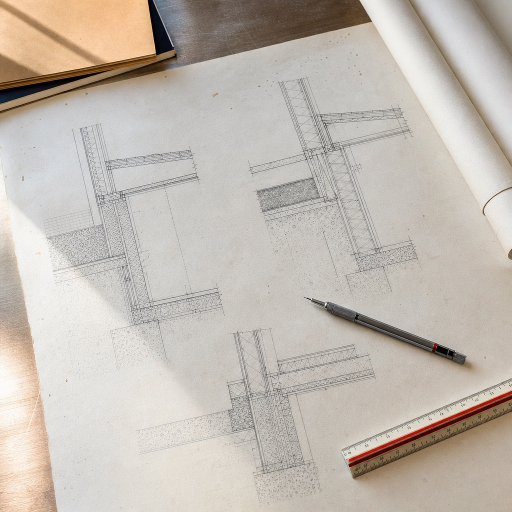
Permanent Wood Foundations (PWF) constructed to the standards of the National Building Code - 2023 Alberta Edition (NBC(AE)) provide a high-performance below-grade system for Alberta residential construction. Achieving true code compliance in both construction and documentation demands meticulous attention to material selection, detailing, and coordination-on the plan sheets, in annotated details, and throughout the permit process. Every dimension noted and annotation made must be rooted in actual code sections, tied to local Alberta STANDATA interpretations, and cross-checked against jobsite realities and inspectors’ most common redlines. This comprehensive discussion follows the full trajectory of PWF detailing-from footing plate to MEP penetrations-with a focus on what truly matters on Alberta drawings, permit submissions, and jobsites.
Dimensioning and Material Specification: PWF Wall Assemblies, Footing Plate to Top Plate
Stud and Sheathing Schedules under NBC(AE) 2019 Section 9.3
Alberta Part 9 prescribes all facets of PWF stud and sheathing schedules, referencing Table 9.3.2.1 for all dimension lumber. Typical residential PWF walls utilize 2x6 (38x140 mm) pressure-treated studs at 400 mm (16”) on center. Details on architectural plan sheets must call out both dimension AND grade with treatment: e.g.:
- “2x6 PWF Studs @ 400 O.C. - CSA O80 Series, Minimum No. 2 SPF, CCA-Preserved”
Wall sheathing is always exterior-grade, 12.5 mm (1/2") thick plywood or OSB with pressure-preservative treatment conforming to CSA O80 and legible, code-accepted face stamp. A correct wall section detail will include:
- “12.5 mm PWF-rated Plywood/OSB Sheathing, Exterior/CSA O80, CCA Pressure-Treated, Face-Stamped”
Plan-review redline: “Sheathing call-out must include CSA O80 & verification note for preservative type; submit certificates with permit package.”
Fastener Types, Corrosion Resistance, and Connection Detailing
Section 9.23.3.4 of NBC(AE) establishes fastener requirements for wood-frame construction. For PWF assemblies in Alberta’s high-moisture soils, hot-dipped galvanized steel nails are required for both stud and sheathing connections. Plan details must call out:
- “Studs to plate: 3.25” hot-dipped galvanized common nails, 2 per connection.”
- “Sheathing to studs: 8d hot-dipped galvanized nails @ 150 mm O.C. edges, 300 mm O.C. field.”
Plan reviewer comment: “All fasteners in PWF walls must be galvanized per 9.3.2.9(2); update generic ‘nail’ symbols to specify finish.”
Treated Lumber and Preservative Certification Call-Outs
Lumber for foundations must comply with CSA O80 series-generally CCA preservative for Alberta residential. Wall section call-outs and Schedules A/E should specify:
- “All PWF Sawn Lumber and Panels: Factory pressure-treated to CSA O80, Use Category UC4.1, CCA, provide mill certificate with deliveries.”
The permit reviewer will redline generic “pressure-treated” call-outs as insufficient, demanding field or shop certificates as permit conditions as per local STANDATA.
Assembly Dimensions and Section Detailing
Typical Alberta PWF wall detail for permit drawing (referencing code and standard practice):
- Footing Plate: 2x8 (38x184 mm) treated, fastened to 150 mm (6”) washed gravel pad, call out: “2x8 PWF Plate, CCA-PT, CSA O80”
- Studs: 2x6 @ 400 mm (16”) OC, min. No. 2 SPF, CCA-treated, call out: as above
- Sheathing: 12.5 mm (1/2”) plywood or OSB, see call-out above
- Top Plate: Double 2x6, CCA-PT, call out: “2-2x6 PWF Top Plate, CCA-PT, CSA O80”
Drawings must show section bubbles referencing wall assembly sheets (“Refer to Detail 2/A4.2 for Full PWF Wall Assembly”). All component call-outs reference actual material specs and code section numbers where practical, e.g., “Per NBC(AE) 9.3.2.1, Table 9.3.2.1”.
Local Amendments, STANDATA, Plan-Review and Permit Submission
Alberta-issued STANDATA documents, accessible at alberta.ca/building-standata, may override prescriptive NBC tables in specific soil/geology contexts encountered in southern Alberta. Permit script typically includes a note: “PWF wall assemblies and all treated elements to comply with current Alberta STANDATA and CSA O80-provide supplier certification documents at framing inspection.”
Below-Grade Envelope Detailing: Weeping Tile, Damp-Proofing, Backfill, Sump Pit
Weeping Tile System: Drawing, Spec, and Slope Detailing
NBC(AE) 2023, Section 9.14.2.1, makes weeping tile a mandatory defense against hydrostatic pressure at the base of PWF wall assemblies. The architectural and foundation drawings must display:
- “100 mm (4”) Ø Perforated PVC Weeping Tile with Geotextile Filter Sock-Minimum 1% Slope to Sump Pit”
- Section detail showing tile placed at or below the bottom of the PWF footing plate
- 150 mm (6”) granular (washed gravel) envelope above and beneath the pipe
Plan reviewers routinely redline “missing slope arrow on drainage system” or flag non-compliant materials if the detail lacks the phrase “geotextile-encased.”
Damp-Proofing and Waterproofing Membranes
Section 9.13.2.1 requires damp-proofing-bituminous spray or similar-over all below-grade portions of the PWF sheathing. Where site conditions suggest a high water table or poorly draining soils, a robust membrane system such as 60-mil self-adhered sheet waterproofing (e.g., Blueskin WP 200) plus a drainage board is often required, per code and best practice.
- Foundation elevation / wall section must call out:
- “Damp-proofing: Bituminous (CAN/CGSB-37.2-M89), continuous from bottom of footing plate to finished grade.”
- “Waterproofing [if required]: 60-mil Self-Adhered Sheet Membrane (Blueskin WP 200 or equal), fully lapped and rolled.”
- “Dimpled Polyethylene Drainage Mat (e.g., Delta-MS) over membrane.”
Permit reviewer note: “Clarify where damp-proofing transitions to full waterproofing; add membrane section with labeled lapping and protection board.”
Granular Backfill Placement and Protection Board Requirements
Section 9.12.3.2 dictates clean, coarse gravel or crushed stone for the first 300 mm (12”) adjacent to foundation wall, compacted in 200 mm (8”) lifts. Specifications on site and section plans must read:
- “Free-Draining Granular Backfill, Type ‘B’, Compacted in 200 mm Lifts-No Clay or Fines Within 300 mm of PWF Sheathing.”
Where drainage mat/dimpleboard is required, details must show:
- “Install Dimpled Drainage Board Over Waterproofing Prior to Backfill to Prevent Membrane Damage”
Field inspections frequently redline the failure to protect the below-grade membrane during backfilling.
Sump Pit Integration: Location, Sizing, and Notation
The NBC(AE) and most local Alberta municipalities require a connected sump pit for all PWF foundation weeping tile systems. Typical specification:
- “Sump Pit: Polyethylene, 750 mm (30”) deep, min. 0.25 m² plan area, airtight cover per local bylaw.”
- Section detail (“See Detail 3/A4.4 - Sump Pit and Tile Integration”)
- Pipe entry: “Weeping tile enters at mid-depth, 100 mm (4”) above pit floor”
Plan reviewers invariably redline “sump pit location not shown on mechanical” or “no discharge path indicated for pumped outflow.”
Anchorage and Lateral Restraint Detailing: Hold-Downs, Anchor Bolts, Connection Schedules
Wall-to-Footing Connection: Anchor Bolt Detailing per NBC(AE) 9.23.6.1
For PWF, the base plate must achieve positive anchorage to prevent uplift and sliding. The Alberta code minimum:
- “12.7 mm (1/2”) Ø Hot-Dipped Galvanized Anchor Bolts @ 2.4 m (8’) O.C., Min. Embedment 178 mm (7”) in Concrete Footing-One Within 305 mm (12”) of Each Plate End”
Section and plan details require anchor positions symbolized along footings, referenced to a “Wall-to-Footing Anchorage Detail (1/A4.3).” Code section 9.23.6.1(2) must be notated to avoid permit conflict.
Inspector’s redline: “Verify anchor bolt embedment-add dimension and show anchor/hardware schedule on plan.”
Wall-to-Floor Joist and Rim Joist Connections
NBC(AE) calls for strong mechanical coupling between PWF wall tops and floor framing. If joists run perpendicular to the wall:
- “Joists: Secure to Top Plate with 40 mm x 4.76 mm Galvanized Steel Straps or Simpson StrongTie H1 Clips @ 2 m (6.5’) Max. O.C.”
- “Fasten per manufacturer’s published schedule and NBC(AE) 9.20.11.1 requirements.”
- Detail: Section cut through wall/joist intersection on sheets A4.2/A5.1
Parallel joists require strapping across three adjacent members for lateral transfer-show on plan and 3D isometric details if possible.
Shear Wall and Inter-Component Ties
Intersecting PWF walls, or transition zones between wood and other assemblies, are tied using heavy-gauge straps or engineered hold-down anchors. Architectural plans must call out:
- “Hold-Down Anchor (Simpson HDU Series or Equal), Specified per Structural Engineering Schedule, @ Shear Wall Ends and Corners-Verify Uplift Calculations per NBC(AE) 9.20.11.3.”
- “Metal Strap, 38 mm x 600 mm, Galvanized, At All Intersecting Walls-Lap and Secure Both Sides”
Permit reviewer’s measured redlines: “Omit generic ‘tie as required’-reference manufacturer, embedment, and code section in note.”
Connector and Fastener Specifications
All inter-component connectors exposed to below-grade conditions must be hot-dipped galvanized. Typical fastener notes for drawing call-outs:
- “Hurricane Plate/Strap Fasteners: Hot-Dipped Galv. Nails, Size per Manufacturer”
- “All Connectors per ICC-ES ESR, 2023 Catalogue”
Framing and Dimensioning Openings: Headers, Sills, Jack Studs, and Moisture Detailing
Headers: Sizing, Section Notation, and Code Reference
Opening header requirements in PWF walls follow NBC(AE) Section 9.23.12.2 and 9.23.12.3. Each window/door schedule must tie to an appropriately detailed plan section:
- “Lintel/Header: [e.g., 2-2x8 SPF No.2, CCA-Pressure Treated], Sized per NBC Table 9.23.12.2A for [Span = 1200 mm]”
- “Support: Jack Studs Each End, [e.g., 2-2x4, CCA-PT] Per 9.23.12.3”
Header depth is annotated above each opening, either in plan or elevation (“See Detail 5/A7.1”). For large openings, “Engineer-Designed LVL Header, shop drawings required” is a standard call-out.
Common inspector comment: “Header schedule missing or does not reference code; resubmit with full spans and loads.”
Sill, Cripple, and Opening Framing Dimensions
For windows, sills and their supporting cripple studs distribute vertical loads and build out nailing surfaces. Standard detail:
- “2x6 Pressure-Treated Sill, Supported by Cripple Studs at Max. 400 mm (16”) O.C., Typ. for All Window Openings”
Plan sheets note rough opening (R.O.) sizes coordinated with window/door schedules and add an installation note: “Verify all R.O. against approved window/door submittals prior to constructing opening.”
Moisture and Air Sealing at Penetrations: Flashing and Barriers
NBC(AE) 9.25.2.1 and 9.25.3.1 mandate a continuous air/vapour barrier system in all exposed above- and below-grade wall sections, and 9.27.3.1 requires that all wall penetrations (like window/door heads/sills) are fully protected from precipitation.
- “Install Self-Adhered Membrane Sill Pan at All Window Sills and Door Thresholds”
- “Head and Sill Flashing: Metal or Liquid-Applied, Lap Minimum 100 mm Each Side, Direct Water to Exterior”
- “Seal Perimeter with Low-Expansion Polyurethane Foam PLUS Bead of Paintable Exterior-Grade Caulking”
Top-grade details will also include: “Continuous Poly Vapour Barrier, Tape and Seal at All Penetrations, Overlap Min. 300 mm at Joints.”
Inspector's field note: “Window lacks sill pan; water ingress risk-remediate per NBC 9.27.3.1. Add detail to drawing set.”
Common Jobsite Call-Outs and Inspection Focus
- Undersized Headers: “Header for 1375 mm opening must be 2-2x10 PT, not 2-2x8-see 9.23.12.2A.”
- Jack Stud/Omitted Trimmers: “Missing second jack at door header; frame opening to match plan details.”
- Flashing/Barrier Missing: “No head flashings or air barrier wrap; install and verify tape lapping.”
- Fastener Incorrect: “Interior fasteners at sill not galvanized; replace for PT lumber.”
Integrating MEP Penetrations: Sleeves, Seals, Firestopping, and Plan-Set Coordination
MEP Sleeves and Structural Backing in PWF Walls (ABC 9.10.3.1 Note 16)
All joints must be backed with lumber at fire-resistance rated PWF assemblies (Table 9.10.3.1.-A, Note 16)-a highly Alberta-specific, frequently-missed plan detail. Architectural and MEP coordination drawings must clearly indicate:
- “MEP Penetration Sleeve-2 Nominal Pipe Sizes Larger than Pipe/Conduit-Install 38x140 mm (2x6) Backer at All Joints, Per ABC 9.10.3.1 Note 16”
Details (A7.12 or similar) will show pre-cut holes with pressure-treated lumber sleeves or PVC pipe sleeves passing through the wall assembly, labelled to match penetration schedule.
Common plan-check note: “Backer required for all joints per ABC 9.10.3.1 Note 16-not shown in Detail 7A/A6.1. Revise and resubmit.”
Waterproofing and Air Barrier Continuity: Penetration Seals
Below-grade PWF wall penetrations must be gas-tight and waterproofed to preserve the building envelope. Details and mechanical plans should note:
- “Pipe/Conduit: Passes Through Sleeve with 10 mm Annular Gap-Fill Gap with Closed-Cell Backer Rod, Tool Intumescent Sealant (3M Fire Barrier 2000+ or equal), AND Install Link-Seal or Equivalent for Waterproofing”
Above-grade PWF penetrations require continuous vapour barrier taping and low-expansion foam fill, again referenced in a dedicated “Penetration Waterproof/Firestop Detail” sheet (A8.x).
Inspection note: “Conduit not fully sealed at exterior-install Link-Seal around sleeve per detail A8.2 and re-inspect.”
Firestopping and Code-Required Assembly F-Ratings
For assemblies with a required 1-hour fire-resistance rating (per ABC 9.10.3.1), penetration firestop systems must meet or exceed F-rating of the host assembly. Penetration schedule to specify:
- “Firestop System: Tested, Listed-e.g. 3M FB-1000NS or Hilti CP 606-1hr F-rating minimum, Tightly Fit with Mineral Wool Backer”
- “Provide certification of listed system with occupancy permit”
Permit reviewer redlines often specify: “Generic fireseal not accepted-list ULC-tested system compatible with PWF wall (wood framing, gypsum, exterior sheathing) and pipe type.”
Plan-Set Coordination and Penetration Schedules
Detailed, coordinated penetration schedules on the architectural set (A9.x or A10.x) must tabulate:
- ID/elevation of each penetration
- Exact size/location (referenced to grid/section lines and grade datum)
- Piping/conduit material and diameter
- Required sleeve/penetration type and firestop system
- “Firestop-Required” column and “Waterproof-Required” column checked ‘YES’ as applicable
Discrepancies between architectural, mechanical, and plumbing disciplines are a common source of field-change orders and inspection delays. On Alberta sites, pre-construction review meetings (with all trade foremen and the inspector, where possible) should cross-check the penetration schedule prior to rough-in.
Drawing call-out example:
- “See Penetration Schedule Sheet A9.1, Detail 8/A8.2 for Typical Firestop & Sealant Detail at 50 mm Ø ABS Drain Through PWF Wall”
Specific Material Call-Outs for MEP Sleeves and Seals
- Sleeves: Schedule 40 PVC (for non-fire-rated), Galv. Steel where fire-rating or structural transfer is required, sized at pipe size plus minimum 38 mm annular space; “to be installed and sealed prior to backfill.”
- Sealants/Firestop: 3M Fire Barrier 2000+ or Hilti CP 606-list product and ULC system #; “Intumescent, self-expanding, tested to CAN/ULC-S115, installed per listing.”
- Waterproof Penetration Seals: Link-Seal Modular Seal, Valspar PWF-Exterior Elastomeric, or equal “continuous below grade.”
Conclusion
True Alberta code compliance for PWF foundations depends on integrated, thoroughly referenced drafting practices: precise dimensioning, explicit code-call-outs (e.g., “Per NBC(AE) 9.14.2.1”, “See STANDATA 19-BCJ-002”), material and fastener certifications specified on plans, and a plan set that enables seamless plan review and site translation of every critical detail-from wall studs to sump pit, and from mechanical sleeves to sill pans. The difference between a smooth permit and costly delays is most often found in the discipline of construction documentation and the code-referenced clarity of every note and section.
Kingsway Drafting & Design supports Alberta builders, developers, and homeowners with deep code knowledge and impeccable construction drawing discipline, streamlining PWF compliance from first sketch to final inspection.