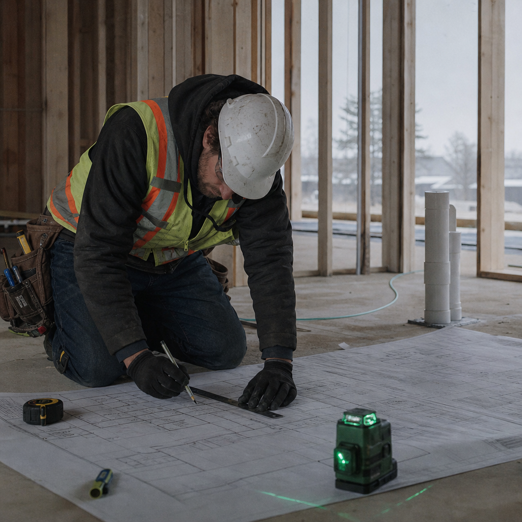
Accurate plumbing vent pipe sizing and layout on Alberta residential drawings hinges on a detailed application of the Alberta Building Code, especially NBC(AE) Part 7, and a disciplined approach to plan documentation, spatial coordination, and response to plan review and field issues. Missteps-incorrect fixture-unit calculation, missing frost protection details, uncoordinated vent runs-result in costly redlines and jobsite rework. Direct integration of code references and explicit dimensioning is essential from plan annotation through plan check and construction handover. Each step, from fixture count to field RFI response, must map precisely to Alberta’s regulatory expectations and specific construction realities.
Precise Fixture Unit Calculations and ABC(AE) Table Application in Vent Pipe Sizing and Drafting
Applying Fixture Unit Calculations and ABC(AE) Table 7.5.8.3. in Sheet-Level Documentation
Vent pipe sizing on Alberta residential plans is determined explicitly by fixture unit loads and developed vent lengths, with strict reference to Section 7.5.8.3. of the 2019 Alberta Building Code and Table 7.5.8.3.. These requirements are non-negotiable: every vented fixture, from the most remote basement floor drain to the third-storey lavatory, must be included in the hydraulic load calculations. The resulting total fixture unit count directly drives vent riser sizing and layout, as must be shown on plan.
- Code callout: “All branch vents, vent headers, continuous vents, and circuit vents shall be sized in accordance with Table 7.5.8.3., based on hydraulic load and developed length.” (ABC 7.5.8.3.)
- Fixture Unit Matrix (typical callout): A schedule on the plan or riser diagram tabulates fixture units per fixture (see Table 2.6.3.2.A for fixture-unit values), total per branch, and the vent size proposed. Example: “Tub/Shower (1.5 FU), Water Closet (4 FU), Lav (1 FU): Total 6.5 FU; 2” vent per Table 7.5.8.3. max 18m developed length.”
- Developed Length Annotation: Plan or isometric diagrams should clearly show each vent’s developed length (not simple run-length), with key junction distances dimensioned. For example, a 1½” vent serving 8 FUs cannot exceed 30m developed length (Table 7.5.8.3.).
- Plan review redline (actual notes): “Vent pipe undersized: revise 1½” to 2” for 14 FUs per Table 7.5.8.3.,” “Developed length of circuit vent exceeds Table 7.5.8.3., increase pipe size or introduce additional vent.”
Air Admittance Valves (AAVs), Compliance, and Plan Jurisdiction
Where AAVs are used, Section 7.5.9.3. requires explicit plan annotation: “AAVs not permitted in supply or return plenum or in areas exposed to freezing. Must be accessible and installed as per manufacturer’s instructions. At least one vent must terminate to open air (ABC 7.5.6.5.(1)).” Drafters must confirm AAVs’ locations on mechanical plans and cross-reference “AAV PER ABC 7.5.9.3.-REFER TO MANUFACTURER'S DATA, PROVIDE ACCESS AT FINAL FINISH.”
Sheet Conventions: Riser Diagrams, Floor Plan Call-Outs, and Dimensioning
Successful plan submissions provide:
- Vent Riser Diagrams fully dimensioned to indicate all vent pipe sizes, fixture unit loads (per fixture and branch), developed lengths, and the Table 7.5.8.3. reference. Arrows and notes indicate direction of flow and termination point.
- Plan Annotations with explicit pipe sizes, “VENT PIPE: 2”Ø, 12m DEV. LENGTH, 9 FU. SIZED PER ABC 7.5.8.3.” Each vent’s pipe material (“PVC SCH 40”), slope (“ALL HORIZ. VENTING MIN. 1:50”), and termination (referenced to specific detail) are included.
- Detail Drawings for complex groupings (“Basement bathroom group, SEE DTL 5/A102: 2” wet vent, 14 FU, 10m, upsizes to 3” before roof.”)
Material and Slope Specifications
Only PVC, ABS, or cast iron pipe approved for venting may be shown. Code-mandated slope (“1:50 min.”) and maximum developed length are always called out. Typical notation: “1.5” PVC DVW, 2% SLOPE TO STACK.”
References and Best Practice
The ABC 2019 and current STANDATA bulletins must be referenced directly on sheets; plan review authorities will flag any deviation. For example, “VENT AND DRAIN SIZING PER ABC 7.5.8.3., STANDATA PLUMB-19.”
Spatial Coordination of Vent Piping within Residential Structure: Clash Detection and Concealed Runs (ABC(AE) 7.5.2.x)
Clash Avoidance with Structure, HVAC, and Electrical
Vent pipe runs in floor assemblies, wall cavities, and ceiling spaces must be coordinated directly with structural, mechanical, and electrical systems on plan. ABC(AE) mandates vent routing “as directly as possible” (ABC 7.5.6.2.), which sharply limits the kinds and number of offsets, especially horizontally below flood level. Plans must dimension all crossings and penetrations, as well as own discipline’s requested notching or boring, to coordinate on engineered framing drawings.
- Sample redline: “Re-route kitchen vent to avoid TJI web-coordinate with structural for joist hole size and location per joist manufacturer's limit.”
- Code callout on section or detail: “VENT PENETRATION THROUGH JOIST PER TPI GUIDELINES; COORDINATE WITH FRAMING SUPPLIER.”
- Minimum clearances: Plans dimension vent pipe away from combustibles or other systems (“50mm MIN. TO ELECTRICAL CONDUIT; 25mm MIN. TO FRAMING CLAD MATERIAL”).
Documenting Concealed Runs: Sections, Elevations, and Coordination Notes
- Detailed Building Sections/Elevations show vent pipes within wall cavities, through floor assemblies, and in proximity to other elements. Dimensioned references: “1½” VENT, 38mm FROM FINISH FACE, 89mm STUD CAVITY, 25mm CLR. TO GWB EACH SIDE.”
- Coordination notes highlight mechanical/electrical conflicts: “TUB VENT TO BE ROUTED ABOVE HVAC SUPPLY DUCT; VERIFY CLEARANCE WITH MECH SHEETS AT FINAL COORDINATION.”
BIM and Manual Clash Detection
Building Information Modeling (BIM) is increasingly used, but many Alberta projects still operate with 2D CAD. Drafters must proactively overlay their piping layouts atop structure and HVAC runs to ensure clearances are met before permit submission. “SEE MECH/ELEC/STRUC SHEETS FOR COORDINATION; FIELD COORDINATION REQ’D AT FRAMING.” is a standard note for home builders.
Concealed Runs and Inspections
- Plan review comment (actual): “Vents routed horizontally more than permitted below flood level-revise to vertical or provide detail per ABC 7.5.6.2.”
- Inspection fail/call-back basis: Unnoted offsets, sharp bends, or mechanical duct/pipe crossing that preclude code min. slope or access.
Mastering Wet Vents & Common Vents Per ABC(AE) 7.5.3.X: Drawing Annotation, Pipe Sizing, and Plan Review Comments
Wet Venting and Circuit Venting: Pipe Sizing and Layout Annotation
Alberta’s code provides for both wet vent and circuit vent arrangements under ABC(AE) 7.5.2 (Wet Venting) and 7.5.3 (Circuit/Common). Wet venting-most commonly employed for compact group bathrooms-demands that all sizing, layout, and limitations be recorded graphically and textually on working drawings.
- Vent Sizing (typical note): “2” PVC WET VENT: SERVES (1 WC, 1 LAV, 1 TUB-TOTAL 5 FU). MAX. ALLOWED 2 WCs PER 2” VENT PER 7.5.2.”
- Limitation Table (callout): “PER ABC 7.5.2, 2” WET VENT MAX: 4 FU (NO WC) OR 3 FU (UP TO 2 WCs). PROVIDE 3” WET VENT IF GREATER LOAD.”
- Circuit vent annotation: “ALL FIXTURES CONNECTED TO CIRCUIT VENT TO BE ON SAME STOREY PER 7.5.3. No stacks upstream. PROVIDE RELIEF VENT DOWNSTREAM OF MOST DISTAL FIXTURE.”
Detail Conventions and Drawing Requirements
Common venting requires drafters to visually distinguish waste, vent, and wet vent segments in plan and riser diagrams, typically through a unique line type or colour on CAD and explicit labeling (“2” WET VENT”, “VENT UP”, “RELIEF VENT-SEE DTL 4/P101”). Fixture unit tallies are boxed alongside pipe sizing at each branch or vent intersection, not just at the stack.
- Elevation diagrams are mandatory for multi-storey vent stacks or complex groupings. A “SEE RCP & ISOMETRIC FOR ALL CIRCUIT VENT ROUTING” note on the plan reinforces the linkage.
- Pipe sizing matrix (on plans): At each fixture group, “TOTAL FU: 8 - 3” VENT TO ROOF, 3” WET VENT TO BSMT BATH PER 7.5.3.”
Common Plan-Review Comments and Correction Cycles
- “Wet vent oversized-reduce per Table 7.5.8.3. for proper trap protection.”
- “Circuit vent branch has upstream stack-re-route for code compliance per 7.5.3.2.”
- “No relief vent indicated at end of circuit - add per 7.5.3.”
Materials and Fixture Considerations
Alberta code standardizes on PVC, ABS, or cast iron for all vent pipes. On drawings, “MATERIAL: PVC DWV (CSA B181.2)” or equivalent is typical, as is explicit identification of all approved fittings at transitions.
Code-Compliant Vent Pipe Terminations at the Roof Line: Frost Protection, Clearances, and Detailing for Alberta Climate
Frost Protection: Upsizing and Insulation
Vent pipe terminations exposed at or above roof level must mitigate frost closure and snow blockage. ABC(AE) 7.5.6.6. requires that “the vent pipe shall be increased by at least one NPS, to minimum NPS 3, immediately before it passes through the outer building wall or roof,” within the insulated envelope. Elevation and isometric details must show this upsize location, material, and transitions, such as:
- “2” VENT UPSIZED TO 3” (50mm to 75mm) WITHIN INSULATED ATTIC 400mm MIN. BELOW ROOF SHEATHING, PER ABC 7.5.6.6. AND STANDATA 19-BCI-013.”
- “VENT UPSIZE LOCATION BUILDING SECTION: SEE DTL 2/A104.”
Roof Termination Heights and Clearance Dimensions (ABC(AE) 7.5.6.5.)
- Minimum vent terminal height above finished roof: 150mm (6") (callout on plan section at roof penetration).
- Distance horizontally from windows, doors, or air intakes: 3.5m.
- Vertical separation above windows and openings: 1.0m.
- Minimum distance to occupied roofs: 2.0m vertical, 3.5m horizontal.
- Property line distance: 1.8m minimum.
All dimensions are shown on roof plan or elevation. Example note:
“VENT TERMINAL TO BE 150MM (6") ABOVE ROOF FINISH, 3.5M MIN. FROM WINDOWS/DOORS/AIR INTAKES, 1.8M MIN. FROM PROPERTY LINE PER ABC 7.5.6.5. & STANDATA 19-BCI-013.”
Typical Plan Review Redlines and Correction Strategies
- “Vent not upsized at attic-add PVC coupling and upsize to 3” per ABC 7.5.6.6.”
- “Vent too close to operable window on dormer-adjust plan layout to maintain 3.5m horizontal per code.”
- “Roof clearance not dimensioned-add annotation on elevation and plan.”
Flashing, Insulation, and Material Specifications
Details must show flashing method (“PVC/EPDM FLASHING PER 7.2.10.14.”) and insulation type (“Roxul or equal, R-12 min. batt wrap to attic vent extension”). Material callouts such as “3” PVC SCH 40 (CSA B181.2), UV stable above roof” specify compliance. A note for builders: “FIELD-VERIFY ROOF THICKNESS; ADJUST FLASHING AS REQ’D DURING ROUGH-IN.”
Preventing Jobsite Call-Backs
By strictly following upsizing and clearance protocols and ensuring dimensional clarity, cold-climate frost closures and snow loads are avoided-major sources of field call-backs for frozen stacks, interior gas odours, and vent icing. Reference details directly on both plan and mechanical sheets for cross-trade clarity.
Integrating ABC(AE) Part 7 Plumbing Code References on Plan-Sets: Navigating Plan Review and Recording Field Solutions (RFI/ASI)
Integrating Explicit Code References and General Notes
Full code compliance and smoother permit review hinges on direct reference to the relevant code provisions-section numbers and local variance notes-within the drawing set:
- Include a “CODES AND STANDARDS” section in general notes: “ALL DVW SYSTEMS INSTALLED PER ABC(AE) 2019, PART 7; FIXTURE UNIT SIZING PER 7.5.8.3.; VENT TERMINATIONS PER 7.5.6.5.-7.5.6.6. REFER TO ALL APPLICABLE STANDATA.”
- Label individual details and callouts by section: “CIRCUIT VENT PER ABC 7.5.3.1.” or “AAV PER ABC 7.5.9.3.-SEE DETAIL X/P101.”
- Isometric diagrams annotate each branch: “VENT SIZING PER TABLE 7.5.8.3. AND 7.5.8.4.”
Field Issue Documentation: RFIs and Architect’s Supplemental Instructions
When on-site discrepancies or unforeseen conditions arise-say, a vent stack conflicts with a relocated HVAC trunk-the site plumber or builder issues an RFI referencing the plan and ABC code clause (eg: “Vent stack at Grid 3/E conflicts with ductwork; propose offset with additional cleanout. Please confirm acceptability as per ABC 7.5.6.2.”). Architect’s Supplemental Instructions (ASI) respond: “Vent may be offset horizontally minimum possible, all per ABC 7.5.6.2.; maintain min. 1:50 slope, verify developed length remains within Table 7.5.8.3. allowance.”
- All field solutions must be marked up on the plumbing as-built set, calling out code section and justification per ABC Part 7. Example: “Field revised vent offset per ASI #14, ABC 7.5.6.2., approved by inspection 2024-07-15.”
Typical Plan Reviewer Redlines and Prevention by Sheet Documentation
- “Lacks section reference for vent sizing: Please indicate Table 7.5.8.3. and associated fixture unit calc.”
- “General notes incomplete; add reference to local STANDATA for AAV installation.”
- “No code reference for plan deviation; please submit RFI with ABC clause citation.”
Specifying Dimensions, Ratings, and Materials
Where not specified explicitly on standard details, all vent pipe dimensions, slope, and materials are confirmed in both general notes and details, such as:
- “VENT PIPE: PVC SCH 40 DWV, CSA B181.2, SLOPE 1:50 MINIMUM”
- “PIPE SIZE AND LENGTH PER TABLE 7.5.8.3., ALL CHANGES FIELD VERIFIED”
- “FLASHING: SEE 7.2.10.14., PROVIDE EPDM BOOT AT ROOF PENETRATIONS”
- “NOTE: IF SITE ADJUSTMENT REQUIRED, SUBMIT RFI REFERENCING APPLICABLE CODE CLAUSE”
Standard Drawing Conventions for Alberta Plan Sets
- All vent routes color-coded or line-typed on plans and isometrics (“VENT: BLUE DASHED LINE,” “WASTE: SOLID BLACK”).
- Pipe size and length on every run with corresponding code table.
- All details enlarged where vent transitions or terminations occur.
Conclusion
Sheet-level fidelity in vent pipe sizing, layout, and code citation is paramount for successful Alberta residential project delivery. By rigorously following ABC(AE) and detailing fixture unit loads, maximum run lengths, material specs, spatial coordination, and climate-specific vent terminations, all documented with explicit call-outs, plan sets survive permitting and translation to the field. When coupled with responsive plan annotation and robust field/RFI documentation, this approach eliminates redlines and minimizes time lost to construction setbacks-empowering contractors, inspectors, and builders alike to deliver to standard. For drafting teams aiming to set the benchmark in Alberta, these practices distinguish true code compliance from mere plan issuance, a standard consistently delivered by Kingsway Drafting & Design.