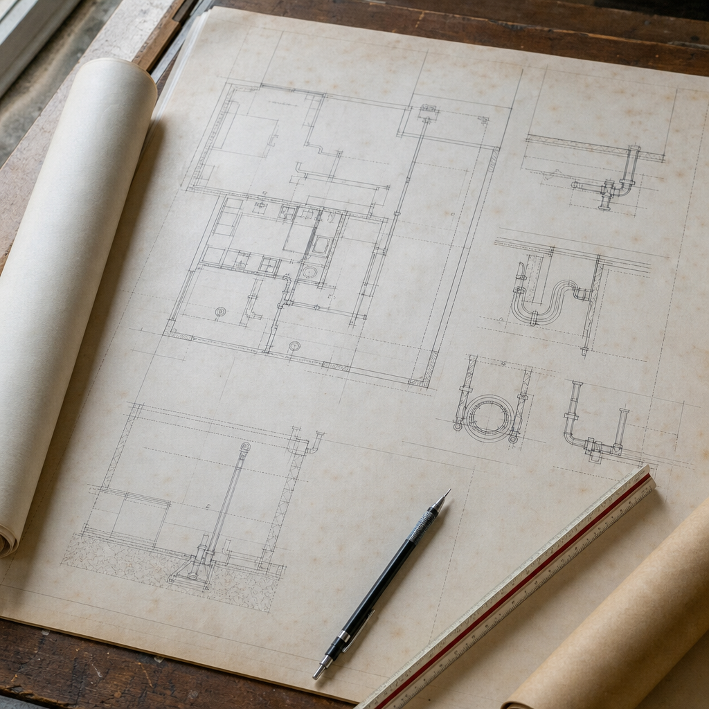
Every year, hundreds of plan-review redlines in Alberta flag missing, misplaced, or improperly dimensioned plumbing cleanouts. Maintaining code-compliant spacing and precise location not only ensures approval at plan review but is also critical for long-term performance, emergency maintenance, and minimizing future remedial demolition. In Alberta, the controlling authority for residential drainage cleanout locations is the adopted National Plumbing Code (NPC), 2020 - with Section 2.4.7 as the reference for drainage systems. Alberta municipal reviewers expect strict adherence to the following cleanout requirements and clear, standard notation on every plumbing plan and detail sheet.
Cleanouts at Base of Stacks
NPC 2.4.7.1.(7) is unambiguous: “A cleanout fitting shall be installed at the base of every soil-or-waste stack.” Drafters must either:
- Show a CO (cleanout) exactly at the base of the stack, or
- Dimension the cleanout not more than 3 meters upstream from the stack base, or
- Place the cleanout on a Y fitting that connects the stack to the building drain or branch (clearly shown and labeled in plan view).
A common annotation: CO AT BASE OF STACK - REF: NPC 2.4.7.1.(7). On residential plan sets, this note typically appears alongside an enlarged “CO” symbol where the vertical stack meets the building drain. Failure to show this detail will result in plan review comments such as “cleanout omitted at stack base - see NPC 2.4.7.1.(7).”
Cleanouts on Building Drains and Sewer Entry
For the main building drain, NPC 2.4.7.1.(6) requires a cleanout located “as close as practical” to where the drain leaves the building. Drafters should dimension this with respect to the foundation wall, referencing both the pipe invert and finished floor level. A typical plan annotation: 4" CO @ 1.0m FROM FOUNDATION WALL - REF: NPC 2.4.7.1.(6).
Where a building sewer is 8” (200 mm) or larger, the code (NPC 2.4.7.1.(4)) escalates the cleanout requirement to a manhole, which is almost never encountered in Alberta residential construction but must be explicitly noted if encountered: “MANHOLE REQUIRED FOR SEWER ≥ 8" - REF: NPC 2.4.7.1.(4)”.
Cleanouts at Changes in Direction
Horizontal pipes changing direction or slope between the house and street/building sewer require cleanouts to maintain one-way rodding at code-defined angles and distances. As per NPC 2.4.7.1.(5):
- Up to 5° per 3 m is permissible without a cleanout.
- Cumulative changes in direction ≤ 45° between cleanouts are allowed (using sweep or Y + 1/8 bends).
Plans must show and dimension all directional changes, with detailed call-outs such as: CO REQUIRED AT DIRECTIONAL CHANGE >45° CUMULATIVE - REF: NPC 2.4.7.1.(5).
Spacing: Maximum Intervals - Dimensioning Conventions on Plan Sheets
NPC Table 2.4.7.2.(1) is the basis for all drawn spacing of cleanouts on horizontal lines:
- Pipes <3": CO every 7.5m for one-way rodding, 15m for two-way.
- Pipes 3" or 4": CO every 15m (one-way), 30m (two-way).
- Pipes >4": CO every 26m (one-way), 52m (two-way).
Dimension strings on plan sheets should use the abbreviation “CO @ X.Xm O.C. MAX” for each branch/run. Example: CO @ 15m O.C. MAX - REF: NPC TABLE 2.4.7.2. These must be dimensioned from CO center-to-center, not footprint edge, and annotated with direction arrows if rodding direction is one-way only.
Graphical Symbols and Standard Annotations
Consistency in graphical communication reduces redlines. Standard conventions in Alberta include:
- CO symbol: Circle (diameter per plan legend, typically 10 mm at 1:50 scale) with “CO” label.
- In riser/stack diagrams: “CO” in a square denotes a vertical stack cleanout.
- Two-way cleanout: Double-headed arrow or explicit “2W CO” note.
Legends must reflect all CO symbols used and annotate each with drawing reference and code section, e.g., “CO = Cleanout, size/type per schedule, install per NPC 2.4.7.1-2.”
Material, Size, and Schedule Specifications
Cleanout fittings and covers must match the drain line in size up to 100 mm (4"), with larger drains requiring minimum 100 mm (4") cleanouts (NPC Table 2.4.7.2). Drafted schedules must reflect this. Materials must follow CSA B70 (cast iron), CSA B181.1 (ABS), or CSA B181.2 (PVC), and specify non-ferrous plugs in ferrous fittings as per NPC 2.4.6.8. Notes should state: ALL CLEANOUTS TO MATCH PIPE MATERIAL, NON-FERROUS PLUGS FOR FERROUS PIPE.
Detailing Cleanout Access and Clearances for Interior and Exterior Installations
Cleanouts that are accessible on paper but unreachable after construction are among the most frequent-and costly-failures. The NPC 2.4.7.4.1 mandate for “readily accessible” cleanouts requires architectural and plumbing drafters to include not just cleanout locations, but also access means and sufficient clearance so maintenance tools and technicians can reach and operate each CO without demolition or disassembly.
Representing Required Clearances and Access Spaces
While the NPC lacks a fixed minimum clearance in millimeters for cleanout accessibility, industry standard in Alberta is a minimum 300 mm x 300 mm (12" x 12") access panel for concealed wall/floor cleanouts. For exterior grade cleanouts, this clear area must extend through surface treatments (sod, concrete, pavers) and be depicted as a hatched square or circle on site plans and foundation plans. A common drawing note: PROVIDE 300x300 ACCESS ZONE CLEAR OF OBSTRUCTION AT ALL CO's.
Interior Cleanouts: Access Panels and Finish Integration
Whenever a cleanout is concealed in a wall or floor, it must terminate either:
- Flush with the finished wall, floor, or ceiling (annotated: CO FLUSH W/ FINISH), or
- Extended to be outside the building envelope.
If a CO sits behind tile, cabinetry, or built-ins, an access panel of not less than 300x300 mm must be clearly detailed, coordinated with partition detail and finish schedules. For fire separations, the panel must satisfy the required rating, which is to be noted: ACCESS PANEL AT CO TO BE 45 MIN. FIRE-RATED WHERE CROSSING DWELLING UNIT SEPARATION.
A frequent plan review redline: “cleanout access panel missing or undersized-NPC 2.4.7.4(1).” Proactive detail sheets should show a 1:5 or 1:10 enlarged detail of the cleanout, insulation, wall structure, and access panel.
Exterior Cleanouts: Recessed Boxes, Covers, and Grade Integration
For cleanouts on exterior walls or at/near grade:
- Specify a frost-resistant cleanout box with a tight-fitting (lockable if required) steel or polypropylene cover rated for anticipated live load (e.g. foot traffic).
- The cover detail must be coordinated with hardscape and landscape plans, stating: CO COVER TO BE FLUSH W/ FINAL GRADE, LOAD-RATED.
- Dimension all exterior COs horizontally and vertically from fixed building corners, showing depth to the extension cap (recommended: no more than 100 mm below finished grade for maintainability).
Any deviation between CO placement and final grades or slopes must be coordinated; drawing call-outs should include: VERIFY FINAL GRADE AND SLOPE FOR CO ACCESSIBILITY.
Coordination with Structural Framing and Slab Conditions
Slab-on-grade installations require special coordination to prevent COs from ending up beneath slab thickening, pads, or footings. Drafting should indicate:
- “NO CLEANOUTS TO BE LOCATED WITHIN FOOTING OR SOG THICKENED AREAS.”
- “FOR SLAB COLD JOINTS, STUB CO EXTENSION TO FINISH PER COORDINATED DETAIL X/A700.”
A recurring field or plan-review comment: “CO obstructed by structural member-not accessible for snake/rodding. Revise.”
Specifying and Drawing Proper Cleanout Fittings and Material Types
Cleanout functionality and long-term durability hinge on both correct fitting type and compatible, code-approved material selection. NPC 2.4.6.1-3, 2.4.6.8 and Alberta amendments spell out the do’s and don’ts of fittings and their graphic representation. Errors in this area routinely yield plan-review notes like “improper cleanout type” or “material mismatch.”
Cleanout Fitting Types: Selection, Use, and Notation
Situational fitting selection for Alberta residential plumbing includes:
- Y-Branch (Wye) Cleanouts: Used in horizontal runs for access in flow direction. Noted by “Y w/ CO” on plan-always include arrow indicating maintenance direction.
- Combination Wye & 1/8 Bend (“Combo”): Provides smoother transitions in tight spots. All combi COs must be sized for the main (not branch) pipe and annotated as “COMBO WYE+1/8 BEND CO.”
- Test Tees: Required on vertical stacks or as “cleanout tee.” Plan notes: “TEST TEE AT BASE OF STACK TO NPC 2.4.7.1.(7).”
- Two-Way Cleanouts: Used at the junction of building drain and sewer or where backflow protection is needed. Annotated as “2W CO” or “TWO-WAY CLEANOUT.”
- Directional Cleanouts: Used at complex direction changes-note direction with arrow and “DIRECTIONAL CO.”
Cleanout Plug and Cover Materials: Specification and Code Compatibility
Cleanout plugs and covers must be corrosion-resistant and match the compatibility of pipe material. As per NPC 2.4.6.8:
- No ferrous plug may be installed in a ferrous fitting or pipe; all threaded plugs must be non-ferrous (e.g., brass) within cast iron or steel pipe systems.
- ABS and PVC systems require compatible threaded plugs or solvent-welded caps; notation should state: “CO PLUG TO MATCH SYSTEM - ABS FOR ABS, PVC FOR PVC.”
- For cast iron: “BRASS THREADED CO PLUG - REF: NPC 2.4.6.8(1)”
Schedule tables included in plan sets should row by row list:
- CO number or tag
- Serving branch or stack
- Type/fitting (test tee, wye, two-way, etc.)
- Material
- Plug type
Example entry: CO-05, BLDG DRAIN, 2W CO, PVC, PVC PLUG.
Graphical Symbols: Discipline in Drafting
Standard symbols reduce both contractor error and plan review confusion. For Alberta:
- Circle with “CO”: Floor or wall cleanout.
- Square with slash or “CO” label: Stack or vertical cleanout.
- Double arrow: Two-way cleanout.
Legend should clearly reference meaning, e.g., “CO: Cleanout, detail/schedule as indicated; 2W CO: Two-way cleanout per schedule.”
Common Drafting Errors and Redline Mitigation
Typical avoidable errors include:
- Failing to upsize CO plug for >4" pipe per code
- Using ferrous plug in cast iron fitting (flagged by plan reviewer as “improper plug material-NPC 2.4.6.8”)
- Omitting direction arrows for cleanout on directional runs
- Incorrectly swapping test tee for wye in a location not allowed (“improper cleanout type-NPC 2.4.7.1”)
- Placing CO symbol without matching detail or schedule entry (“CO TYPE NOT SPECIFIED” redline)
Review plansheet call-outs before submission: every CO symbol must refer to a standard schedule detail and include the relevant material spec and code reference.
Integrating Alberta Building Code References and Mitigating Plan-Review Redlines for Cleanouts
Explicit cross-referencing of code sections within drawing call-outs and keynotes is a primary mitigation against approval delays and plan-review redlines in Alberta. Plan reviewers commonly cite missing references and incomplete drafting-drafters should embed code call-outs, abbreviations, and detail tags directly where each cleanout occurs.
Code Section Referencing on Drawings
Key plan-sheet annotations for Alberta’s code environment include:
- At every base-of-stack CO: “CO @ BASE OF STACK - REF: NPC 2.4.7.1.(7)”
- For changes of direction: “PROVIDE CO @ CHANGE OF DIRECTION >45° - REF: NPC 2.4.7.1.(5)”
- For access: “ALL COs TO BE READILY ACCESSIBLE - NPC 2.4.7.4.1”
General notes should specify: “ALL DRAINAGE CLEANOUTS TO COMPLY WITH NPC 2.4.7 INCLUDING SIZE, SPACING, AND ACCESSIBILITY.”
Mitigating Redline Comments: Plan-Review Analysis
Plan reviewers most frequently tag cleanouts with:
- “Cleanout omitted”: A cleanout is missing at a required location-usually at stack bases or main outfall. Most often cured by strict plan check using “CO @…” code-referenced annotation for every stack and drain branch.
- “Insufficient accessibility”: A CO is shown but with no access (e.g., in mechanical room corner, behind casework). Fix by dimensioning required 300 x 300 mm access zones and noting “NO PERMANENT OBSTRUCTION-CO ACCESS PANEL AS SHOWN.”
- “Improper cleanout type”: Wrong fitting for application, often seen at base of stack (missing test tee) or horizontal run (wye instead of two-way). Proactively specify in both plan and schedule, e.g., “TEST TEE CO-REF: NPC 2.4.7.1.(7)” and match symbol in all sections and details.
Proactive Drafting Techniques: Standardization and Coordination
- Keynote system: Assign each cleanout a keynote linking directly to the schedule, with the full code clause in the keynote legend (“KN-05: CO at base of stack to NPC 2.4.7.1.(7)”).
- Detail cross-referencing: Every CO symbol carries a bubble tagged with detail and schedule-e.g., “CO-01 - See Detail 5/P502.”
- General notes: “All cleanouts and access panels to conform to NBC(AE) Part 9 and NPC 2.4.7; verify on site any concealed locations prior to framing inspection.”
Proactive integration of code citations directly on plan sheets-rather than relegating to specs or a code matrix-prevents most red-line cycles tied to “compliance insufficiently documented.”
Jobsite Call-Outs, Rough-In Coordination, and Troubleshooting Cleanout Installations
Field installation success is overwhelmingly determined by the clarity, dimensional accuracy, and coordination provided on construction drawings. Missing or misplaced cleanouts on site most often result in RFIs, change orders, and exposed non-compliance at plumbing and occupancy inspection.
Essential Field Call-Outs and Coordination Notes
Drawings must include distinct installation call-outs for each cleanout:
- “VERIFY FFL FOR CO EXTENSION”: Direct the contractor to align CO with finished floor level based on the actual site build-up-critical for basements where slab or finish elevation may vary. Show vertical dimension on detail, e.g., “CO CAP 75mm ABOVE FINISHED SLAB.”
- “COORDINATE ACCESS PANEL WITH WALL FINISH SCHEDULE”: Triggers field coordination between the mechanical and architectural trades to ensure no tile, panelling, or cabinetry blocks CO access-dimensioned on partition details.
- “PROVIDE 300x300mm ACCESS PANEL FOR CLEANOUT”: Specifies minimum panel size for any concealed CO, matching the code and local industry practice.
- “DO NOT BURY CLEANOUTS BENEATH SLAB/FINISH”: Prevents COs from being inadvertently covered by topping or under-slab insulation; critical on basement or renovation projects. Call-out example: “CO TO REMAIN EXPOSED THRU SLAB FINISH-COORD. INSTALL SEQUENCE.”
- “COORDINATE WITH ALL CONCEALED UTILITIES”: Avoids field conflicts with electrical, gas, or HVAC services by demanding layout review at rough-in, reducing site relocation RFIs.
Critical Rough-In Dimensioning
- Cleanouts servicing horizontal drainage in habitable spaces must terminate within 100 mm of finished floor (per Alberta industry best practice-see Kingsway Builders). Plan and section must show floor-to-cap distance, often as: “CO CAP AT 75mm A.F.F.”
- Access panels must be dimensioned laterally and vertically relative to room finishes-if the access panel is behind casework, note: “CASEWORK FIELD MODIFIED FOR 300x300mm CO ACCESS PANEL.”
- Exterior COs must be not more than 100 mm below final grade, with flush cover shown in section. Plan call-out: “CO COVER 50mm BELOW FINISHED GRADE - FLUSH WITH HARD/PAVED SURFACE.”
Preventing Jobsite Challenges, RFIs, and Post-Occupancy Maintenance Issues
- Buried Cleanouts: Regular failures arise from poor documentation or unclear cap heights, resulting in COs installed before floor pours and forever lost beneath finished flooring. To avert, require: “FIELD VERIFY CO LOCATION AFTER SLAB PREP AND PRIOR TO POUR.”
- Utility Conflicts: Mechanical, electrical, and structural conflicts are minimized by mandating coordinated shop review and walkthrough, and by aligning CO dimension strings to the established building grid or measure-off structural features rather than notional walls.
Plan annotation: “CO LOCATION TO BE FIELD-VERIFIED WITH MEP/STRUCT PRIOR TO INSTALL.” - Incorrect Height or Location: Wrong-side-of-wall or misplaced floor elevation settings can only be avoided if dimensioned precisely from both established control lines and finished grades. Provide two dimensions for each CO: e.g., “1200mm FROM S.A. WALL, 75mm ABOVE FFL.”
- Obstructed/Missing Access: All cleanouts must be unobstructed by permanent fixtures, cabinetry, or finishes. If an access panel is required, coordination with architectural elevations and finish schedules is vital. Elevation notes: “COORDINATE ACCESS PANEL LOCATION W/ ROOM ELEVATIONS.”
Material and Cover Specifications Detailed for Field Compliance
Field success is frequently determined by clean, unmistakable specification statements adjacent to each CO call-out and schedule:
- “ALL CLEANOUT CAPS TO BE NON-FERROUS IF INSTALLED IN FERROUS PIPE - NPC 2.4.6.8(2)”
- “CO COVERS FOR EXTERIOR APPLICATIONS TO BE LOAD-RATED, LOCKABLE WHERE EXPOSED”
Field Redline Examples and Quick Corrections
RFIs and redlines commonly appear as:
- “CO buried by finished slab-relocate or provide access panel.”
- “CO installed behind electrical panel-move to clear.”
- “Access panel undersized-not compliant with 300x300 mm requirement.”
Clear and standardized drawing call-outs, with accompanying schedule and detailed elevations, resolve nearly every chronic field challenge. Coordination notes on the G-sheet or M-sheet general notes, and overlay coordination models where feasible, are strongly recommended for larger or more complex builds.
Conclusion
Detailed, code-anchored drafting of drainage cleanouts-encompassing location, spacing, access, fitting type, material, and explicit plan call-outs-ensures both regulatory compliance and practical constructability across Alberta’s residential landscape. By integrating precise code references, unambiguous dimensions, coordinated detail sheets, and jobsite-focused call-outs, drafters and designers eliminate the most persistent barriers to timely approvals, error-free installation, and maintainable infrastructure. Kingsway Drafting & Design’s meticulous approach positions every project for seamless review and long-term reliability.