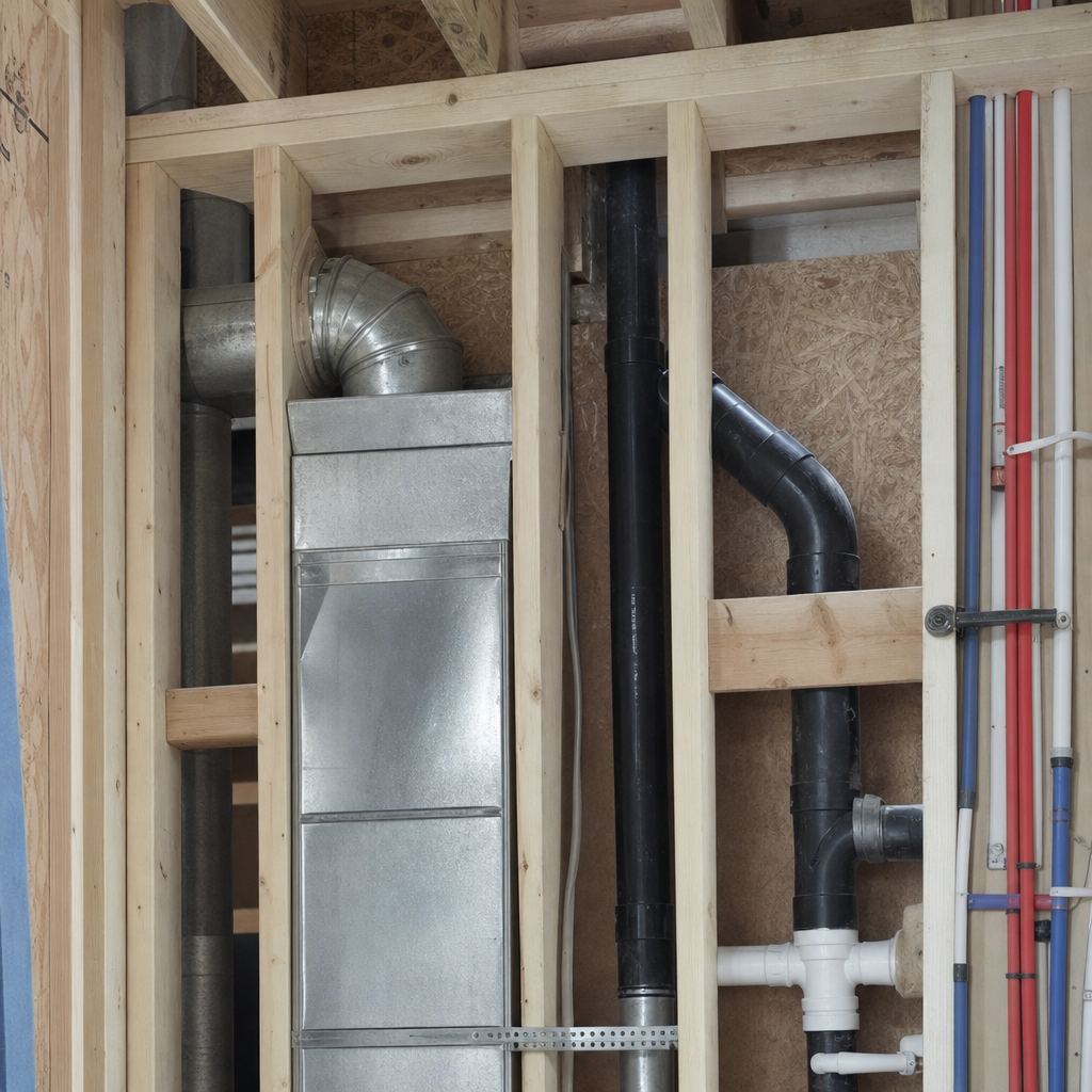
Notching, boring, and routing of large mechanical and plumbing systems in Alberta residential buildings is one of the most challenging aspects of architectural drafting, requiring rigorous attention to Alberta Building Code (ABC) dimensional limits, built-up member design, penetration firestopping, and explicit, cross-referenced detailing between architectural, structural, and MEP sheets.
Detailed Drafting of Structural Modifications for Large MEP Penetrations
Mechanical and plumbing systems routinely demand significant structural accommodations in Alberta homes-extended rectangular trunks for heat recovery ventilators, 10"x24" supply mains, 4" DWV stacks, and multi-branch supply risers. Drawing these penetrations or routings onto floor or wall framing plans triggers a host of code provisions under NBC(AE) 2023 9.23.5.1 through 9.23.5.7, as well as potential requirements outlined in Alberta's STANDATA bulletins.
Notching, Boring, and Alteration Limits
- Holes in floor, ceiling, or roof joists: NBC(AE) 9.23.5.1 strictly limits holes to no more than one-quarter the member depth (d), with centerlines at least 50 mm from edges, unless the member's depth is increased by the diameter of the hole.
- Notching of framing: NBC(AE) 9.23.5.2 restricts notches at joist ends to one-quarter depth, while top notches (within 1.5d of bearing) to one-third. For a 2x10 joist (actual 235 mm) that means an end notch or hole up to 58 mm, with explicit dimensioning required on plan over/under duct or pipe centerlines.
- Wall studs: Load-bearing studs must maintain at least two-thirds of their depth undisturbed, per NBC(AE) 9.23.5.3. Non-load-bearing studs notched or drilled must retain at least 40 mm.
- Top Plates: Penetrations or notches in double or single top plates cannot reduce the undisturbed width to less than 50 mm, except with reinforcing detail. All material call-outs (fasteners, steel plate gauge, sistering requirements) must be specified adjacent to penetrations in plan and section.
- Roof Truss Alteration: Per 9.23.5.5, field modification-whether hole, notch, or coped passage-of a roof truss member is strictly prohibited unless shown on sealed manufacturer's truss drawings.
Plan Sheet Implementation and Detail Conventions
- Annotation and Dimensional Clarity: All proposed notches and holes are circled in redline review if dimension strings or offset notes are missing. Clarify on framing plan: "(2) 58 mm holes at 2500 mm and 2850 mm from grid A, centreline 90 mm below top of joist."
- Section Cuts and Typical Details: Use section keys (e.g., 4/A501) to direct to enlarged cross-sections showing how the mechanical run passes through or below the framing. Standard legend symbols define typical notches, sistering, or steel Z-clips.
- Structural Reinforcement Call-Outs: If notching/boring exceeds code limits, detail "Sister joist both faces with 38x235 SPF No.2, full-length, fasten with 8d nails at 200 mm o.c." or specify steel plate size/fixings per engineer.
Plan-Review Redlines and Common Triggers
- Exceedance of Notch/Hole Limits: Reviewers note: "Hole diameter at duct run exceeds allowable under 9.23.5.1-provide engineer's design and specify reinforcement."
- Placement Adjacent to Bearing: Notches located above supports or near joist ends are flagged ("Notch at grid D/Rim exceeds 1/3 joist depth within span"). Relocating the run or redesigning framing is typically required.
- Omission of Material Specs/Reinforcement: "Bulkhead above supply trunk lacks reinforcing detail and fastener schedule-revise section and call-out."
Examples of Dimensions, Ratings, and Specs (Plan and Section)
- On a basement framing plan: "2x10 SPF floor joists @16" o/c (actual d=235 mm); provide (2) 60 mm holes at 140 mm o.c.; centerline of hole min. 60 mm from bottom; reinforce as per Detail 5/A502."
- For a supply trunk in a main floor beam drop: "Beam dropped to 400 mm below subfloor to allow passage of 14" round duct (outside diameter 363 mm); beam designed per engineer to accommodate dropped bearing at grid 4/C; see section 9/S301."
- Material spec: "Steel reinforcing plate to ASTM A36, min. 150 mm x hole diameter, 3 mm thick, secure to both sides of joist with (6) 12-gauge wood screws, staggered within 50 mm of hole edges."
STANDATA and Alberta Amendments
- STANDATA bulletins are referenced at the bottom of detail blocks: "Structural modification for MEP per Alberta STANDATA 14-BCV-016 and ABC(AE) 9.23.5.4-See Alberta.ca"
- When permitted by variance, details must reference engineer’s sealed design and local Building Safety Codes Officer interpretation.
Strategies for Integrating Main HVAC Trunk Lines and Return Air Ducts within Framing Cavities
HVAC trunk lines (e.g., 10x24" rectangular, 14" round) and large return air ducts require systematic integration into joist bays, behind bulkheads, or within floor chases. Every interference results in time-consuming coordination changes, so reflected ceiling plans (RCPs), floor plans, and architectural sections must act as the primary battleground for clash avoidance and code compliance.
Soffit Dimensions and Bulkhead Construction
- For a 10x24" rectangular duct, draft soffits with a minimum inside clear of 12x26", allowing 1" insulation and 1" air space above and beside. Plot soffit width and drop on both RCP and section (e.g., "Soffit: 300 mm deep x 650 mm wide, 2.1 m above FFL; see reflected ceiling plan note 7 and Section 4/A701").
- All soffits indicated for mechanical runs must provide minimum finished clear ceiling heights (not less than 2.10 m per ABC 9.5.3.1), with specific notes locating dropped portions: "Provide 7200 mm long x 350 mm deep bulkhead adjacent to mechanical room, min. 2100 mm clear AFFL-see RCP key 2."
Vertical Chases
- Supply, return, and HRV trunk lines passing up or down are shown in plan as dashed rectangles or circles, cross-referenced to section details referencing both typical chase framing and insulated duct assembly.
- Dimensioned chase widths must accommodate both duct OD and statutorily required clearances (see NBC(AE) 6.2.3.19, "Ducts and plenums must maintain clearance from combustible construction as per 3.6.5.6"). Note: "Duct chase, 14"x14" clear (min.), 18" x 18" framed, provide 2x4 stud min. on all four sides; insulate per mech. schedule."
Floor/Wall Penetrations
- Each mechanical trunk or take-off shown passing through floor or wall membranes must include a penetration key (e.g., "Ref: Penetration Schedule, Detail 7/M401"), and diagrammatically shown in elevation/section within architectural and mechanical sets.
- Fire-rated assemblies: add balloon call-out "(P1) Provide UL-classified firestop system with F rating = assembly (45 min/1 hr)" and reference in general notes.
Clash Avoidance and Coordination Notes
- RCP uses differentiated line types (dashed for supply R/A, solid for exhaust/HRV, cross-hatch for plumbing bulkheads) to separate service runs.
- All potential interferences are tagged: "Verify above ceiling: duct cross-over with 4" PVC DWV in proximity; coordinate offset as required-see Section 10/M501".
- General notes include: "No penetration of primary floor beams permitted without structural engineer review; coordinate all mechanical offsets with framer prior to rough-in."
Code, Material, and Dimensional Call-Outs
- Rectangular duct sizes (e.g., 10x24, 14x8) are noted on each trunk, with supply/return arrow and CFM if relevant for energy code review.
- Duct material noted: "26 ga. galvanized steel (min.), SMACNA Table 1". Insulation spec: "R6 foil-faced glass fibre insulation on all duct in unconditioned space".
- Fire-damper integration called at all rated assembly penetrations, shown: "FD-1 fire damper, ULC listed, with access: see Detail 13/M900".
Plan-Review Redlines and Jobsite Review Notes
- Reviewer: "Return air trunk at southeast corner projects below min. ceiling height-revise bulkhead to 2.1 m AFFL and note depth on all relevant RC plans and sections."
- Jobsite clarification: "Field verify joist depth at grid 2/A before rough-in of 14" round-modify penetration if depth less than 360 mm; submit RFI for change approval."
Coordinating Large Diameter DWV and Supply Risers within Multi-Storey Framing
Drainage, waste, and vent (DWV) pipes (esp. 3"-4") and supply risers must traverse multiple structural zones-joist/deck penetrations, stud bays, and chase builds-without undermining framing, fire/barrier continuity, or finished heights. Detailed isometric and plan documentation is essential for both design approval and construction execution.
Isometric Details for Wet Vents and Horizontal Runs
- Plumbing isometric diagrams specify all DWV runs, pipe sizes, fitting types/angles, and required slopes. Example note: "4" PVC main stack (wet vented), 45° long sweep, min. 1:50 slope (2%), branches as per ABC 7.5.8.1 hydraulic limitations."
- Offset limitations: e.g., "Single offset permitted above first storey, 2.5 m max. length for 4" stack-see ABC 7.5.8.1."
- Vent connections for each fixture group shown, with fixture units tabulated adjacent to each vertical (F.U. legend on plan and iso sheet corner).
Chase and Stud Bay Coordination
- Dedicated plumbing chases are dimensioned to suit largest group (e.g., stacked 3" DWV, 1" supplies, insulation), as in "Plumbing Chase: 14" x 18" clear, min. 90 mm from stud face to pipe centerline; frame 2x4 @12" o/c, double layer drywall per fire rating".
- Where large DWV is forced into load-bearing stud walls, call-out required: "Reinforce double studs both sides, maintain min. 64 mm undisturbed per ABC 9.23.5.3; engineer review required if further reduction."
Dimensioned Locations for Rough-Ins on Plans
- Plumbing and architectural plans are fully dimensioned to grid lines or finished walls: "4" stack centre 1350 mm from east wall, 2200 mm from grid B-coordinate with floor penetrations, see section 6/P601".
- RCP and bulkhead callouts for horizontal runs: "DWV horizontal: 4" PVC pipe, soffit drop 300 mm x 450 mm wide, finish height 2.15 m AFFL; see reflected ceiling plan and Detail 12/A802."
- Sections provide vertical dimensions from FFL to pipe centerline, plus finished clearances, e.g., "4" main sewer, centreline 1750 mm AFFL at lowest point; finish drywall 2.10 m below joist per ABC 9.5.3.1."
Plan-Review and Field Comments
- Reviewer: "No fire separation detail at bulkhead penetration in demising wall-provide detail callout and specify listed assembly type."
- Field: "Rough-in DWV conflicts with engineered floor truss; submit revised run to avoid truss web; RFI required."
- Dimension clarity: "Dimension the length and location of all soffits for DWV and show relationship to finished ceiling at return-non-conforming as drawn."
Drawing Conventions, Legends, and Schedules
- Every plumbing plan and iso sheet includes a legend of symbols (DWV, supply riser, vent, cleanout) and a rough-in schedule tabulating service, location, dimension to nearest grid, and elevation above FFL.
- Detail bubbles cross-reference all major rough-in penetrations: circle, detail number above, sheet number below (e.g., 12/P601).
Code Specs and Material References
- DWV slopes: "3" pipe: 1:50 (2%); 4" pipe: 1:100 (1%) per Appendix A ABC Table 7.4.10.7."
- Fire separation: "Bulkhead at rated floor: (2) layers 16 mm type X gyp., caulked at all junctures, tested to CAN/ULC-S101".
- Pipe materials: "DWV: CSA B182.1 certified PVC; supply: Type L copper or PEX A/B, manufacturer's cut sheet to accompany shop drawing."
Drawing Management and Clash Detection Protocols for MEP/Framing Coordination
Efficient integration of large mechanical and plumbing runs within residential structural cavities in Alberta increasingly depends on advanced drawing management-both in 2D set conventions and in 3D digital models. BIM-based clash detection, meticulous layer management, and rigorous detail cross-referencing form the backbone of modern residential documentation.
BIM/Clash Detection Workflow with Revit/Navisworks
- Discipline models (structural, architectural, mechanical, plumbing) use Alberta project's shared coordinates for exact overlay in Navisworks Manage. Models federated as NWC/NWD files.
- Navisworks clash test: run "MEP vs. Framing" and "Ducts vs. Joists/Beams" rule sets with a hard tolerance (e.g., "Report all intersections over 5 mm").
- Clash reviews generate issue lists, each tagged to drawing location and system, e.g., "Clash #21: 4" DWV riser intersects steel beam at grid 5/E-refer Detail 6/S402 and RFI #18."
- Resolution tracked with status ("Active," "Resolved," "Require RFI"), with comments uploaded to drawing issue log.
Layer Management and Drawing Set Protocols
- All plan sets employ standardized layer naming convention: ARCH-, STRU-, MECH-, PLUM- prefixes, per AEC CAD Standards. Item-specific layers-e.g., MECH-DUCT-TRUNK, STRUC-JOIST-OPENING-enable quick isolation of MEP routes or structural modifications.
- Layer filters/templates applied to consultant backgrounds to toggle between "Clear Framing Only," "Show Concealed MEP," and "Plan Review: Clash Mode."
Standardized Cross-Referencing Notes and Detail Keys
- Detail key bubbles and reference notes are coordinated across sheets so that, for example, "Penetration Detail 12/M401" on mechanical matches "Penetration Section 16/S701" on structural and call-out "Bulkhead Assembly 7/A802" on architectural.
- Cross-indexing: Drawings maintain a penetration schedule ("See Schedule S403") and a master index: "All MEP/structural coordination details referenced by dual keying system-number per discipline sheet series."
- Symbols and abbreviations are explicitly defined in a project legend at the start of each plan set.
Plan-Review and Redline Triggers
- Reviewer comment: "Duct pass-through at grid G/7 conflicts with header drop at same location on structural-revise both sheets for alignment."
- Redline: "Layer convention not consistent-modify architectural, structural, and MEP to match project standard for plan overlays."
- Reviewer field report: "No cross-reference between detail 8/M601 and 9/S502 for chase reinforcement-provide consistent detail bubbles on all affected sheets."
Sheet Call-Outs, Detail Numbering, and Drawing Convention
- Title blocks reference discipline, sheet number, and revision for traceability: "A-501: Architectural Framing Details; S-401: Structural Sections; M-701: Mechanical Penetrations".
- Grid lines and column lines shown on all plans, with major intersections referenced in dimension strings for all large duct/plumbing runs.
- Penetration details indexed in both a "Penetration Schedule" (service, location, opening size, required rating) and on the drawing via bubble and section cut symbol-e.g., 12/M501, 8/S501, 9/A802.
Navigating ABC for MEP Penetrations and Firestopping Requirements
Every large mechanical or plumbing run passing through fire-rated assemblies, demising walls, or between suites engages specific firestopping obligations under ABC Part 9 (esp. 9.10.9.6-9.10.9.9), with critical implications for plan annotation, field verification, and code compliance.
Fire-Rated Assembly Penetrations and Detailing
- Penetrations through fire separations must be sealed with a listed firestop system, with F or FT rating equal to or greater than the assembly (e.g., 1 hr wall = min. 1 hr rated firestop, CAN/ULC-S115).
- All firestopping details must be drawn in section and plan: "4" DWV pipe, penetration through 1 hr. party wall-see Detail 10/A900; fill annular space with Hilti CP 606 firestop sealant, min. 20 mm thickness all sides, metal collar clipped to drywall both sides."
- Where code permits, outlet boxes or small MEP devices in concealed spaces may penetrate provided the firestop assembly is listed for that condition (9.10.9.8); otherwise, maintain a 600 mm separation horizontally.
Material and Assembly Specifications (Drawing Call-Outs)
- Firestop systems are tagged with listing reference and minimum performance: "Provide 3M FB-3000 fire barrier wrap, F/FT rating 1 hr, as per listed system CAJ 120-7. Firestop schedule on G902."
- All through-penetration firestops must be tested to CAN/ULC-S115 and must match both the wall/floor rating and penetration type (plastic pipe, cable tray, duct, etc.), with annular space and installation method specifically dimensioned on detail.
Common Plan-Review Redlines and Uncoordinated Service Triggers
- Redline: "Unsealed pipe sleeve through rated corridor-add firestop call-out and assembly reference."
- Comment: "Electrical box on opposite sides of wall at grid 4/F with no listed putty pad-revise to provide separation or listed FT-rated device."
- Reviewer note: "Firestop listed as 'caulking' without system reference; revise to full listing, UL/ULC tested, and add to specification schedule."
Jobsite Field Verification and RFI Protocol
- Each penetration is tagged in field as per sheet: "Penetration ID#9 - refer to A900/10; verify assembly and take photos for inspection record".
- If service location or type differs from approved drawing, contractor must submit an RFI: "4" duct passing through 1 hr floor shifted from gridline; propose new penetration at revised location, submit new firestop detail for review."
- Inspection records include installation photos, firestop product labels, and completed schedule checked by installer and third-party inspector.
Specific Dimensions, Ratings, and Product Examples
- Firestop material: "Annular space: 12 mm min., 25 mm max.; seal with Hilti FS-ONE Max sealant, certified CAN/ULC-S115, 1 hr F rating".
- Combustible outlet box: "If not protected with FT-rated firestop, maintain min. 600 mm horizontal between opposing boxes-see Plan Note 2/A901 and ABC 9.10.9.8".
Integrated Documentation Ensures Code-Driven Coordination and Constructability
Coordinating large MEP runs through residential framing in Alberta demands unparalleled rigour in cross-discipline documentation. Maximum permitted notching, boring, and fire-rated penetrations must be dimensioned and cross-referenced between architectural, structural, and MEP sheets using standard conventions (detail bubbles, penetration schedules, BIM-linked overlays) and explicit Alberta code citations to avoid field conflicts and failed inspections. From specifying a 58 mm hole 90 mm below joist top in compliance with 9.23.5.1, to dimensioning an 18" chase for 4" DWV, to documenting firestop products listed to CAN/ULC-S115, these best practices-when fully implemented-not only avert redlines but ensure safe, efficient, code-compliant homes from plans to turnover.
Kingsway Drafting & Design brings these code-driven coordination strategies to every Alberta residential project, ensuring precision, compliance, and constructability at each drawing milestone.