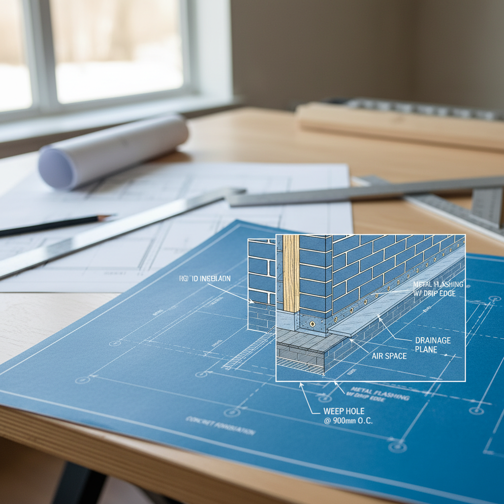
Moisture management within the wall assemblies of Alberta’s homes is a decisive factor in the long-term durability and thermal performance of residential structures. Nowhere is this more evident than in the proper detailing and drafting of masonry veneer weep holes and flashing systems. In the province’s demanding climate, even a minor lapse in moisture control at the design or construction stage can lead to expensive callbacks, structural repairs, and compromised indoor environments further down the road. As of May 1, 2024, the National Building Code - 2023 Alberta Edition (NBC(AE) 2023) sets forth explicit, enforceable requirements that drafters, architects, and builders must not only follow, but understand in detail to ensure resilient, code-compliant masonry veneers.
Why Weep Holes and Flashing are Fundamental to Wall Performance
Water works its way behind even the best-built masonry claddings-through mortar cracks, porous units, misaligned joints, wind-driven rain, or capillary action. Once inside the wall assembly, this moisture seeks the path of least resistance, collecting at the base of cavities or lingering behind window and door heads. Left unmanaged, this trapped moisture accelerates:
- Mold and Mold Spores: Forms in humid, confined spaces behind veneers, compromising indoor air quality.
- Freeze-Thaw Cycling: Water that freezes inside walls expands, causing cracking, spalling, and displacement of masonry units.
- Corrosion: Embedded steel (anchors, wall ties, or lintels) rusts rapidly when chronically moist, threatening structural safety.
- Insulation Degradation: Wet insulation loses R-value, diminishing the home’s energy efficiency and leading to condensation issues.
Weep holes and flashing work in tandem: weep holes form the drainage route, evacuating water to the exterior, while flashing collects and channels water from critical points within the cavity to these weep holes. Designing and drafting these systems with precision is both an art of foresight and a science grounded in the latest building code mandates and material sciences.
Code-Compliant Weep Hole Placement: NBC(AE) 2023 Requirements and Real-World Application
Effective weep hole design starts with precise placement and appropriate spacing, as prescribed by NBC(AE) 2023. Every cavity wall, whether full-depth masonry or masonry veneer (brick or stone cladding anchored to a structural backup), must include weep holes at the bottom of the air space, just above the flashing. This configuration does not only pertain to the base of wall sections; the code is clear that every cavity or airspace, including those above lintels and flashing at windows, is subject to these rules.
Spacing and Locations
- Base of Wall Veneers: Weep holes are required at the lowest course of brick or stone veneer, directly above the foundation sill or brick ledge. Spacing must not exceed 800 mm (~31.5 in)-drafted as a maximum center-to-center requirement for each wall segment.
- Above Flashing at Lintels: Each window, door, or opening that interrupts the normal drainage plane must have a cavity or airspace above its lintel. Here, new weep holes must also be drafted into the veneer directly above the flashing, observing the same 800 mm maximum spacing.
- Corners and Wall Returns: Special attention must be paid to wall terminations, inside corners, or returns where isolated cavity segments may form. Weep holes should always be specified in such a way that no ‘dead zones’ or undrained pockets remain after masonry installation.
Best Practice-Drafting for Functionality
- Coordinate with Structure: Depending on the wall backing (concrete, wood frame, steel stud), place weep holes where water will pass easily over the flashing and out of the assembly-never below a continuous steel shelf angle or any discontinuity that could act as a water dam.
- Consistent Detailing: In drafting drawings, clearly indicate the spacing dimension and label each required weep location, including above all flashed openings, parapets, and stepped foundations.
- Clear Draining Path: Draft a cavity air gap of at least 25 mm (preferably more in Alberta’s climate), ensuring water falling into the cavity can move freely towards the nearest weep hole. Use section call-outs to show continuity of the drainage plane around corners, sills, and transitions.
Material Options and Detailing for Weep Holes
Weep holes can be formed using several methods, each with practical drafting and construction implications:
- Open Head Joints: Simply omitting mortar from vertical joints at the designated locations creates unobstructed weeps. This is commonly specified and easy to draft, but during construction, may be partially filled if not properly supervised. Include material notes and enlarged details to emphasize their importance.
- Weep Tubes (Plastic or Metal): Inserted into the head joint, these tubes (typically 10 mm to 12 mm diameter) provide a reliable exit regardless of mortar slumping. However, they must not become clogged, so their inclusion in shop drawings and specifications must be paired with cleanout and inspection instructions.
- Mesh/Insect Screens: Specify mesh inserts or purpose-made screens to fit inside open joints or tubes, blocking insect entry while allowing drainage and airflow. These are critical in areas where insects or rodents may exploit open weep locations.
Flashing Details: Exacting NBC(AE) 2023 Code Provisions and Applications
Flashing is the backbone of cavity wall water management. It provides the horizontal barrier that collects water and guides it toward weep holes-protecting sills, lintels, and the top of building elements from moisture intrusion. Thoughtful drafting of these components is essential, as correct placement and integration often spells the difference between a dry, healthy wall and premature deterioration.
Required Flashing Locations
- Beneath Jointed Masonry Window Sills: Flashing is not optional beneath sill courses-especially where the sill is sloped and jointed. It should extend out to the face of the wall, then up behind the sill block. This prevents water ingress at the vulnerable window-to-masonry interface.
- Over Parapet Heads and Copings: Parapets, whether above rooflines or at balcony edges, are mapped points of water entry and freeze-thaw concern. Draft flashing that fully wraps the back and top of parapets and returns down each side to direct water outward.
- Heads of Glass Block Panels: Glass block assemblies in Alberta’s climate need robust horizontal flashing above to shed water that could otherwise seep downward along mortar joints.
- Beneath Weep Holes: Every course of weep holes must sit directly above flashing surfaces. The flashing is typically sloped outward and extends beyond the building face or ledge for positive drainage.
- Lintels over Openings: The code introduces a stipulation for window or door head flashing whenever the vertical distance from the frame head to the eave’s bottom exceeds one quarter of the overhang’s horizontal projection. This means if openings are close to the eave, flashing may not always be required, but for most modern residential designs with tall walls or short overhangs, it is a must.
Flashing Dimensions and Upstands
One of the most nuanced elements in drafting is the geometry of flashing. The NBC(AE) 2023 mandates that, for masonry veneer over wood-frame walls:
- Flashing must project no less than 5 mm beyond the face of the supporting building element (i.e., out past the shelf angle, foundation ledge, or supporting trim).
- Flashing must rise at least 150 mm up the face of the wood-frame backup, under the sheathing membrane or insulating sheathing, as shown for compliance in wall section details.
This vertical upstand is critical to prevent “wicking” of water over the backup wall and into the insulated cavity or framing. In all detail sections, the flashing termination should be shown turned up behind the sheathing membrane-a point often missed in incomplete or generic shop drawings.
Material Transitions and Compatibility
Material selection is a function of intended lifespan, wall assembly type, and chemical compatibility:
- Stainless Steel: The gold standard for longevity, especially in severe climates or commercial-scale projects. Requires careful isolation from copper or dissimilar metals to prevent galvanic reactions.
- Copper: Durable and easy to form; it patinates over time and provides exceptional weather resistance. However, runoff can stain adjacent stone or brick, so specify with caution and provide isolating layers as needed.
- Rubberized Asphalt Membranes and Peel-and-Stick Flashings: Suitable for most residential applications, compatible with wood framing, and easy to install around complex corners and returns. Must be protected from ultraviolet light, typically by the overhanging masonry course.
- Polymeric Flashing: Engineered sheets can offer flexibility, easy lap-jointing, and good service life at modest cost, but require secure terminations and compatible adhesives or sealants.
Integration with weather-resistive barriers is paramount: the WRB must be lapped over the upturned leg of the flashing (“shingled” in drainage direction), not merely abutted or left behind. Incomplete or reversed laps are a common and costly site error; detailed drafting must highlight these intersections with large-scale callouts and explicit notes.
Integrating Flashing and Weep Holes with Wood-Frame Veneers
Wall Section Detailing for Alberta’s Climate
In Alberta, the majority of residential homes use wood-frame backup walls with brick or stone veneer. This assembly is particularly vulnerable to moisture cycling given the temperature extremes, wind loads, and freeze-thaw cycles in the region. Thus, code-compliant flashing must not only function during initial construction but continue to protect the assembly for decades.
- Shelf Angle and Ledge Details: At the foundation, a brick ledge or steel shelf angle provides support for the masonry. Draft the flashing to extend a minimum of 5 mm past the outer face and ensure the drip edge is clear of obstructing elements below.
- Upstand Integration: The 150 mm vertical upstand behind the veneer is clearly shown positioned behind the sheathing membrane or rigid foam. If multiple layers are present (e.g., WRB over foam), the flashing is installed behind both, maintaining the one-way drainage path outwards.
- Termination at Sills and Heads: Large-scale details at window sills and heads must indicate the flashing return up the jambs or with end dams at both ends, preventing water from leaking into the assembly at vulnerable terminations.
- Clear Air Cavity: Specify a continuous drainage mat or mesh at the base of the cavity to prevent mortar droppings from bridging the gap and blocking the weeps.
At every transition-from wall to window, from veneer to parapet, from below-grade to above-grade-drafting must reflect not just the “what” but the “why” of flashing continuity, positively directing water to the exterior in all realistic site scenarios.
Practical, Constructible Weep Hole and Flashing Drafting-From Drawings to Built Reality
Addressing Construction Sequencing and Trades Coordination
The best drafting predicts not only theoretical performance, but also how details will be executed in the field. Drawings must anticipate typical construction practices in Alberta-a sequence often involving:
- Wood framing and sheathing installation
- WRB and window/door flashing installation
- Masonry support placement (shelf angle or brick ledge)
- Flashing installation and lapping under WRBs
- Masonry veneer placement with concurrent weep hole formation
Clear, unambiguous callouts and detail sections should:
- Show which trade is responsible for each step
- Specify shingle order of WRB and flashing to avoid reverse laps
- Include enlarged sections at corners, parapets, window/door transitions
- Reference sample installation methods and mockups when new products or assemblies are used
Keeping Weep Holes Open and Cavities Clear
Mortar bridging and “clogged cavities” are among the most frequent causes of failed masonry veneers. Even perfectly spaced weep holes and expertly installed flashing cannot perform if water cannot reach them. To address this, draft:
- Mortar Collection Devices: Specify proprietary drainage mats or fibrous mesh at the footing of the air cavity. These collect dropped mortar, preventing blockages and maintaining a clear path for water to travel to the weep holes.
- Cavity Depth: Increase the minimum air gap beyond 25 mm where possible, as Alberta’s climate makes quick drainage and air movement critical. Detail a continuous, unobstructed cavity space in all section details.
- Access for Inspection: Where practical, draft removable brick units or oversized weep openings at isolated locations to permit post-construction inspection and maintenance if needed.
Sill and Lintel Slope
Both sills and lintels require special attention in the drafting stage to actively shed water:
- Draft stone or brick sills with a pronounced outward slope-typically 1:12 (about 5 degrees)-to prevent ponding. Clearly show this slope in wall sections and elevations.
- The top surface of flashing above lintels must never be level or sloped inward; a min. outward slope of 6 mm over its width is generally accepted best practice. Include dimensions or slopes in detail notations.
End Dams and Side Flanges
Without properly drafted end dams at flashing terminations, water can simply run off the side of flashing segments, potentially re-entering the wall assembly. For all shelf angles, sills, and head flashings:
- Detail vertical “end dams” of at least 25 mm (1 in.) height at each end of the flashing segment.
- Where flashing runs into a perpendicular wall, draft a continuous upturn at the intersection, forming a trough that ensures water detours back to the exterior rather than leaking toward inner corners.
Proper Sealing and Fastener Placement
Penetrations through the flashing for wall ties or fasteners are potential leakage points. In detail callouts, specify:
- Staggered or offset placement of anchors where possible, so that flashing is not perforated in a continuous line.
- Sealant compatible with both flashing and adjacent materials to be applied at all penetrations, laps, and transitions. Specify minimum bead dimensions and detail in section drawings.
Illustrative Detail Examples (Described)
- Base of Veneer Wall Section: Shows foundation wall, projecting brick ledge, upturned flashing with upstand behind WRB, drip edge projecting 5 mm beyond ledge, mortar collection mat at cavity base, and open head joint weep holes spaced at 800 mm o.c.
- Window Head Detail: Lintel supports masonry, continuous flashing over lintel, 150 mm upstand behind membrane, end dam at jamb, outward slope of flashing, and open or tube weep holes above lintel/flashing spaced at 800 mm o.c.
- Window Sill Detail: Sill course sloped out, continuous flashing extends from under sill block to beyond the masonry face, 150 mm upstand, properly lapped WRB, and flashing end dams to direct water to weep holes at ends.
Beyond Code: Best Practices for Long-Term Success in Alberta’s Mixed Climate
The NBC(AE) 2023 establishes the required baseline, but resilient design incorporates additional safeguards commensurate with Alberta’s severe freeze-thaw cycles, seasonal driving rains, and rapid warming and cooling. Proven best practices in drafting and construction make the difference between minimum compliance and exceptional long-term performance:
- Use of Higher-Performance Flashings: Upgrade to stainless steel or fully adhered membranes in high-exposure or tall wall applications for additional peace of mind.
- Regular Inspection and Maintenance Access: Incorporate “access weep” bricks or removable inspection panels for periodic drainage checks, especially in larger or multi-family structures.
- Enhanced Cavity Ventilation: In high-moisture zones (e.g., below garden beds, beside downspouts), specify additional weep holes, cavity vents higher up the wall, or alternate drainage routes.
- Seasonal Construction Considerations: Require temporary winter protection for cavity walls under construction-draft sequences and notes that prevent snow or ice accumulation in exposed cavities.
- Training and Mockups: Call for on-site construction mockups of key details (base, window head, parapet) to verify logic and achieve “buy-in” from all trades before production work proceeds.
Drafting for Inspection, Approval, and Permitting
Complete, meticulously detailed wall sections and enlarged details expedite permitting under Alberta’s code and boost confidence with municipal inspectors. Typical submission sets should:
- Show all required flashing and weep hole placements in plan, elevation, and section.
- Include keyed detail bubbles referencing enlarged details for base, window head, sill, parapet, and any unique transitions.
- List notes regarding material compatibility, minimum slopes, integration sequence, and maximum spacing for weep holes.
- Reference the specific NBC(AE) 2023 article numbers in title block notes or drawing legends for unambiguous compliance tracking.
For multi-family projects or custom homes with complex geometry, color-coded details and isometric “exploded” views further clarify intent during pre-permit review meetings, minimizing costly revision cycles.
Common Errors to Avoid-and How Drafting Prevents Them
- Insufficient Weep Hole Spacing: Spacing above the maximum 800 mm leads to undrained pockets; always dimension and tag weeps on all elevations and sections.
- No Flashing at Vulnerable Locations: Omission under sills, over lintels, or at parapets can ruin entire walls. Use standard detail libraries to ensure no location is missed in drafting.
- Blocked Cavities: Failing to specify mortar collection and enlarged cavity airspace frequently results in blocked drainage. Show these components in every section.
- Wrong Flashing/WRB Lapping: Reverse lap allows water behind the WRB and into the structure. Always detail shingle-lap sequence and specify both in notes and in section graphics.
- Improper Flashing Terminations: No end dams or returned upstands let water escape behind at corners; always show clear vertical terminations in detail bubbles.
Advancing Masonry Veneer Durability-Expert Recommendations
Architectural drafters practicing in Alberta’s climate recognize that superior wall durability results from an integrated approach that starts at the drawing board. Prioritizing code compliance is only the beginning; every additional increment of best practice-be it an extra weep hole, higher upstand, or meticulous lapping-provides exponentially greater insurance against future failure. Always consider the following in every drafting project involving masonry veneer:
- Dimension all flashing, laps, slopes, and projections visibly-avoiding generic, ambiguous “TYP” notes wherever critical to performance.
- Reference all weep holes in plan, section, and elevation; add detail markers to communicate their function to all trades.
- Detail all cavity depths, mortar management devices, and drainage mats.
- Highlight the transition and shingle sequence of membranes and flashing in call-outs and enlarged details.
- Draft for both initial construction and ease of future inspection-periodic maintenance is a fact of homeownership, especially in Alberta’s environment.
By treating every project as an opportunity to set a higher bar for water management in masonry veneers, the drafting process not only assures code compliance but materially contributes to a home’s real-world longevity and resilience.
Conclusion: The Drafter’s Role in Code-Compliant, Resilient Masonry Veneer Walls
Every weep hole, every segment of flashing, and every membrane lap detail drafted into an Alberta home’s plans is a value multiplier for performance, health, and beauty. The NBC(AE) 2023 provides the regulatory baseline, but elevating every project with deeper technical insight sets the stage for homes that withstand Alberta’s elements decade after decade-dry, strong, and energy efficient. For permit sets that pass muster on the first review and walls that stay problem free, meticulous drafting of weep holes and flashing is a hallmark of quality and diligence in residential design.
Kingsway Drafting & Design brings this level of detail and expertise to every project, ensuring your homes, infills, and developments receive the highest standard of architectural documentation and moisture management solutions.