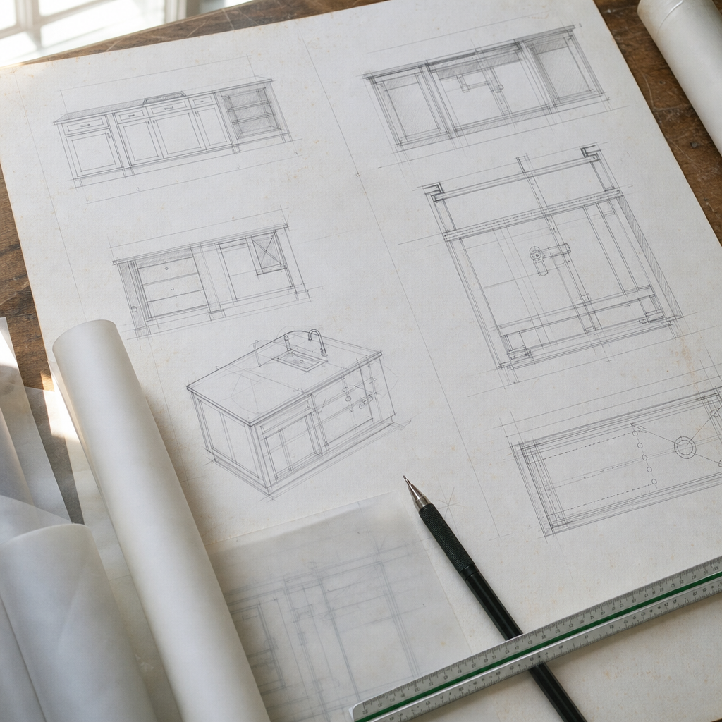
Kitchen islands, when thoroughly detailed on construction drawings, represent a convergence of structure, mechanical/electrical/plumbing integration, and code-conscious coordination in Alberta’s residential sector. NBC(AE) 2023, CEC 2024, and NPC 2020 govern every aspect, requiring detailed coordination during drafting, rigorous notation, careful dimensioning, and meticulous redline resolution for permit approvals and jobsite execution. Every detail matters-from structural cantilevers and anchorage to utility routing, venting loops, and minimum clearances for appliances-if redlines, costly rework, or field change orders are to be avoided.
Part 9 Framing: Structural and Cantilever Requirements for Island Bases
Sheet Representation, Section Cuts, and Anchorage Notation
Every kitchen island in Alberta intended to support significant loads-stone countertops, appliances, cantilevered breakfast bars-must be grounded in the requirements of NBC(AE) 2023 Part 9, especially sections 9.23 (Wood-Frame Construction), 9.23.6.1 (Anchorage of Building Frames), and 9.23.13.5 (Braced Wall Panels in Braced Wall Bands). In the typical plan set, island base framing is never simply boxed out or implied; rather, it’s tied into full-frame plans, with referenced details such as “Detail 5/A3.1” flagged at the island perimeter and section cut indicators (“Section A/A4.2”) revealing joinery, post support, and floor anchorage.
Section 9.23.6.1 requires that every structural frame, including an island with a built-in overhang or support column, is positively anchored to the base floor system, unless engineering explicitly proves this unnecessary. On plan sheets, anchorage is explicit-e.g., “Anchorage: (3) 3/8” lag bolts @ 450mm into TJI rim board; continuous blocking beneath posts, see Detail 5/A3.1.” Material tags call out lumber meeting CSA O86 standards (“38x140 SPF No.2/Better, see Structural Schedule S1”).
Cantilevered Overhangs: Plan-Review Triggers and Dimensioning
Permit reviewers regularly flag island cantilevers exceeding “1/4 the backspan of the supporting joist”-a direct echo of NBC(AE) 2023 commentary. For example, a 2400mm (8'-0") joist backspan yields a max 600mm (2'-0") cantilever unless otherwise engineered. The plan must not only dimension the cantilevered section (“Overhang = 305mm [12”] typ, Max per NBC(AE) 9.23”) but also tag structural detail, such as “joist sistered with 2x10 SPF No.2, 400mm o/c; see Joist Framing Plan S2.”
Redline examples from Alberta municipalities include:
- “Provide structural detail for island overhang support. Dimensioned cantilever exceeds 300mm.”
- “Anchorage to subfloor system not specified. Confirm attachment with callout and enlarged section.”
Adjustments on revised sheets typically result in a new keyed detail showing hidden floor blocking, reinforcing the need for close coordination with structural plans.
Material Specification, Bracing, and Local STANDATA Amendments
Material schedule tables-or direct notation on elevations/sections-include species, grade, fastening, and any requirement for moisture-resistant or fire-rated lumber (especially near appliances). Bracing, per 9.23.13.5, is called out (“Provide blocking/strapping at 400mm o/c within island base, connected to adjacent floor joists”). Where province-wide variances (STANDATA) apply, their reference is added: “Island Framing Anchored per Alberta STANDATA 21-BCI-018, if applicable.”
CEC Rule 26-712(g): Island Receptacles, GFCI, and Appliance Rough-In
Electrical Plan Notation, GFCI ‘TR’ Callouts, and Dedicated Circuits
Under the 2024 Canadian Electrical Code, now adopted in Alberta, every kitchen island with power requires careful sheet annotation for compliance-especially with Rule 26-712(g), which mandates all 5-15R and 5-20R receptacles in dwelling units be tamper-resistant (TR). Dedicate line symbols with “TR” subscript are shown at the island on electrical plans (“E1.1”):
- “(TR)GFCI 15A” at island face, near sink (GFCI requirement flagged per zone),
- “(TR) 20A Appliance Circuit: See Panel Schedule; circuit ID ‘KITCH-ISL1’.”
Legends are explicit: “(TR): Tamper Resistant, per CEC Rule 26-712(g).” Schedules tabulate receptacle type (“Qty 2 @ Island, TR GFCI, CSA C22.2 No.42 compliant”). Any exceptions for inaccessible or appliance-dedicated outlets are cited (“not TR per CEC 26-712(g)(iii): >2.5m AFF, dedicated fridge outlet”).
Wiring Diagrams, Plan-Review Redlines, and Typical Resolutions
Detailed wiring diagrams accompany plan sets for any island with multiple receptacles, dishwasher feeds, or cooktop connections. Conduit routing below slab is shown as dashed polyline, labeled “1/2” ENT to ISLAND, min. 50mm cover below slab.”
Common redlines for island electrical rough-ins include:
- “Island outlets not tagged as (TR). Revise electrical legend and keynote.”
- “Provide GFCI protection for all island countertop outlets-location adjacent to wet area.”
- “Indicate circuit number for dedicated microwave (if shown in island).”
Resolution typically requires both plan annotation correction (“(TR)GFCI callout at each outlet”) and associated updates to electrical schedules and legends.
Material and Specification Notes
Drawings must specify that all devices are CSA-approved, tamper-resistant, and GFCI-protected where in proximity to sinks or other identified wet zones, noting compliance with CEC as adopted by Alberta (CEC, 2024, Rule 26-712(g)). For dedicated appliance rough-ins, plan callouts include circuit and load (“Dishwasher: 120V/15A, dedicated; Cord/plug connection; GFCI-protected, per CEC”).
NPC 2020: Plumbing for Island Sinks and Dishwashers-Loop Venting and Water Layouts
Island Loop Venting: Plan and Isometric Detail Integration
Where island sinks or dishwashers are specified, the requirements of NPC 2020, as enforced in Alberta since April 1, 2023, become central. Island locations rarely permit conventional vertical vent connections. Instead, plans detail an island loop vent-a configuration that rises below the counter (to at least the flood level rim) before returning below the floor and joining the next downstream vent-eligible stack or fitting. Plan annotation is precise: “1-1/2” vent pipe, looped up to 50mm above flood rim, see P2.2 Isometric View, Detail 3/P2.2.”
Alberta STANDATA P-07-12-NPC 05 is often explicitly referenced as a design authority in detail bubbles. Section cuts through the island show both drain and looped vent, dimensioned for minimum heights (“600mm FFE to loop apex”), pipe sizes, and clearance with other floor structure. Cleanouts are tagged: “Cleanout: 2” ABS, accessible from cabinet toe space.”
Water Service and Drainage Layout
Potable supply, hot and cold, is shown with separate line patterns, labeled by size, type, and origin (“1/2” PEX from mech closet, route below slab to ISLAND SINK, min. 50mm insulation”). The entry point is flagged on the main floor plan and detailed in isometric. Sizing for drainage (“2” ABS to island sink”) and the minimum slopes (noted “Min. 1% to stack per NPC 2020 2.4.8.1.”) are called out clearly.
Permitting reviewers commonly call out:
- “Show venting arrangement for island fixture-loop vent required per STANDATA P-07-12.”
- “Drain cleanout missing-add accessible location in island base.”
Revised drawings integrate enlarged isometrics, pipe size/height dimensioning, and schedule for fixture connection (“Island Sink: 2” ABS drainage, 1-1/2” loop vent, cleanout at base, all per NPC 2020”).
Material Notation and Pipe Routing Constraints
Plan legends specify pipe type (“PEX-a: Potable Hot/Cold; ABS-DWV: Drain/Vent; Use CSA B137.5/CSA B181.1 certified materials”). Routing notes coordinate pipe locations with structural layout-e.g., “No 2” drain in engineered joist web openings without Truss Designer’s approval.”
HVAC and Ventilation: Range Hood Ducting, Make-up Air, and Island Appliance Clearances
Duct Sizing and Material on Mechanical Plans
Mechanical sheets (M1.1/M2.1) depict range hood duct runs from island cooktop exhaust to exterior, denoting both horizontal routes (dashed lines) and vertical penetrations (“150mm (6”) Dia. Galv. steel duct per hood mfr; Route direct to exterior; No flex or plastic duct per NBC(AE) 9.32”). Transitions above ceiling are depicted with dotted lines and section bubbles. Plan callouts reference manufacturer specs (“Refer to Range Hood Data, M2.1 Sched. 9 for CFM + Min. Duct Size”).
Make-up Air Requirements and Notation
For high-capacity hoods, NBC(AE) Part 9 requires make-up air (“Provide MUA, sized for range hood exhaust, see Section 9.32.3.13 and CSA F326-2023”). The plan sheets annotate intake/exhaust interaction zones (“Range Hood Exhaust, 900CFM-make-up air intake provided at 1800mm min. separation per 9.32.3.13, see Detail 8/M2.2”). Cross-reference to energy code (“MUA system, HRV-style, 0.5 ACH min.”) is included where required by local BUI/plan checker.
Redline comments frequently highlight:
- “Duct size not specified for range hood. Reference mfr specs and sheet schedule.”
- “Make-up air system/duct not shown/labelled for range hood exceeding 600CFM.”
- “Intake/exhaust separation less than 1800mm-relocate intake or exhaust termination.”
Redlines resolved by adjusted duct layout, relocation of termination points, and updated sheet annotation (“Ext. termination relocated, now min. 2.0m from intake; see clouded revision, M2.2”).
Appliance Clearance Dimensions and Sheet Details
Clearance around island cooktops and range hoods is explicitly dimensioned on plan (“Min. 762mm [30”] above cooktop to bottom of hood or per mfr min., see Elev. 6/M2.3”). Overhead and side clearance to combustibles are shown on both plan and elevation, with notations such as “900mm min. from gas cooktop edge to adjacent vertical surface per NBC(AE) 9.10.21.2.” Where manufactured islands with integral hood/vent are shown, installation manuals are cross-referenced on the plan (“Install per Canon 700 Series Manual, file in permit record”).
Drawing Conventions, Critical Dimensions, and Redline Coordination for Island Details
Sheet Scales, Lineweight, and Annotation Standards
Plans present the kitchen island at 1:50 (1/4" = 1'-0") for context, with enlarged sections and electrical/mechanical details at 1:20 (1/2" = 1'-0") or 1:10 for complex joinery, framing, or venting. Standard line types differentiate elements: solid heavy for framing, medium solid for cabinetry, dashed for utilities below slab, centerlines for symmetry. Notes are directly keyed-“Island Countertop: 305mm [12”] overhang, see Detail 4/A5.1”-and all dimensions clearly marked from both wall datum and adjacent cabinetry.
Critical dimensions from research and Alberta practice include:
- Clearance around island: Minimum 1067mm (42”), labeled everywhere the island abuts traffic or appliance zones.
- Bar seating clearance: Minimum 1118mm (44”) behind stools, dimensioned parallel to edge.
- Counter overhang: 305mm (12”) typical. Overhang >305mm receives note: “Provide steel angle bracket, concealed, see Section 12/A4.3.”
Schedules tabulate finish materials (“Countertop: 30mm thick quartz, non-combustible, see Section 9.10.21.2 NBC(AE)”). Legends and keynote indices clarify symbols for all outlets, fixtures, duct terminations, venting, and bracketry.
Jobsite Call-Outs and Note Placement
Every specifiable item that could be the subject of an inspection or red tag in Alberta jurisdiction gets explicit notation on the drawing-be it “GFCI/ TR Outlet: Install at 600mm AFF, face of island counter, per CEC 26-712(g),” or “Cleanout: Accessible in toe kick, label for water test, see P1.1.” Mechanical notations call for Make-up Air intake and exhaust to be “field-marked and verified by inspection before close-in,” with reference to NBC(AE) Section 9.32.
In the field, redline coordination means all resolved plan comments are updated on every affected sheet: clouded revisions, updated keynotes, and cross-references to both building and trade plans (“See A3.1 for revised island cantilever details and Sheet E1.1 for added (TR)GFCI outlets”). Plan review approval is secured by demonstrating that all code-mandated changes are not only noted in general but dimensioned, detailed, and referenced by accurate code citation and supporting detail/ section views, eliminating ambiguity for every contractor and inspector on site.
Material Schedules and Cross-Referencing
Finishes, cabinetry, structural, electrical, mechanical, and plumbing are all shown on their respective schedules-with cross-references (“Island Framing: per Struct. Schedule S2; Electrical: E1.1, Mech: M2.2, Plumbing: P2.2”). Countertop materials receive fire performance notation per NBC(AE), especially if a cooktop is present. Appliance cut sheets are referenced when clearance dimensions are coordinated (“Installer to refer to attached spec for Canon 700 Series, clearances identified in Section 7/M2.1”).
Plan-Review Redlines and Field Execution: Closing the Loop
Common Redlines for Kitchen Island Sheets in Alberta
- “Clarify structural support for overhangs >300mm-provide detail and dimension anchorage.”
- “Electrical schedule missing (TR) notation at all required receptacles.”
- “GFCI protection not clear at island outlets near sink.”
- “Island sink venting not in compliance-add isometric and label loop vent.”
- “Range hood duct/ MUA not coordinated-detail, dimension, and locate exterior terminations.”
- “Clearances to appliances and passageways need to be dimensioned in plan and elevation.”
Resolution is document-based: clouding updated details, referencing code section numbers (“Anchorage revised per NBC(AE) 9.23.6.1”), and updating all affected schedules and legends. Jobsite call-outs reinforce inspection points (“Inspector to verify loop vent cleanout at base, see P1.1 for dimension and access point”). This rigor ensures not only initial approval but a smoother site process, less risk of variance or call-back, and clearer communication from design through to completion.
Through expert-level drafting, rigorous code referencing, and detailed plan preparation, kitchen islands in Alberta can be delivered with the structural robustness, utility integration, and compliance assurance required for successful residential projects-guaranteed by the deep experience of Kingsway Drafting & Design.