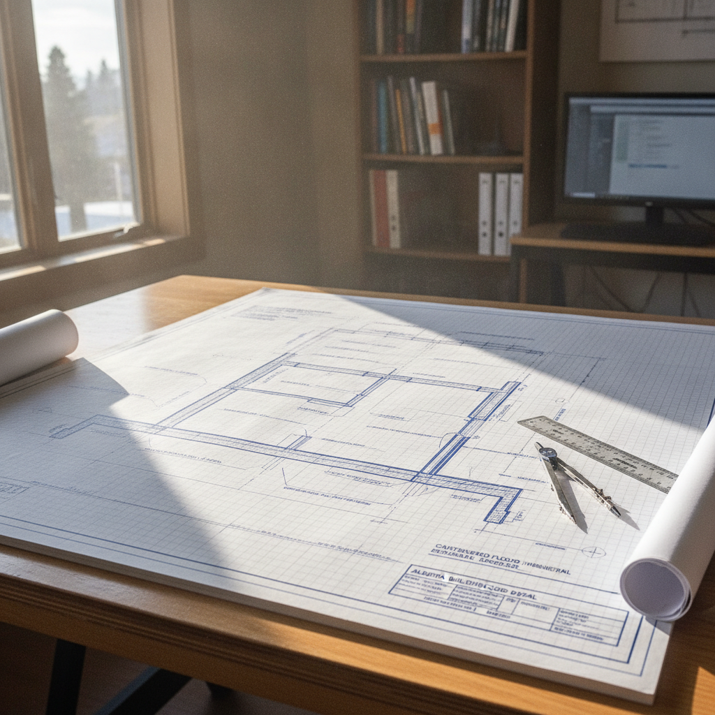
Cantilevered floors-where a building structure projects beyond the foundational footprint-have long been a hallmark of distinctive Alberta residential design, adding both functionality and visual interest to homes across the province. Bay windows that allow sunlight to stream in, breakfast nooks hovering above gardens, and bold modern cantilevered rooms require structural ingenuity, yet they also introduce unique challenges regarding energy performance and code compliance. The underside exposure inherent to cantilevers means that without careful detailing and drafting, these areas can undermine a building’s thermal envelope, contribute to occupant discomfort, and jeopardize code approvals.
Seasonal extremes in Alberta’s climate exacerbate these risks. Frigid winter air meets inadequately insulated cantilevers, allowing cold spots and condensation to infiltrate homes. Inadequate air barriers-an all-too-common oversight where multiple assemblies intersect-translate to drafts, higher energy bills, and even hidden moisture issues that can foster mold within floor cavities. Drafters, designers, and site teams must grapple not only with NBC(AE) 2023’s clear prescriptive requirements, but also the practical realities of field implementation and future durability.
Code-Compliant Assembly: What NBC(AE) 2023 Demands
Thermal Performance Criteria: Meeting Alberta’s Requirements
For homes or suites where a heated space sits above an unheated area or directly above exterior air-precisely the scenario with a cantilevered floor-Article 9.25.2.1. of NBC(AE) 2023 mandates a minimum effective thermal resistance. Alberta’s climate zone dictates that this value is typically R-31 (RSI 5.5), an aggressive threshold that reflects the severity of heat loss when assemblies are exposed on multiple sides.
The R-31 requirement is not an “average” across assemblies in a house; it is a minimum for each insulated section over an exterior or unheated space. Cantilevered floors are not exempt and must meet this minimum even if the overall home R-value is higher elsewhere. This is especially critical because cantilevers can function as thermal “bridges” if insulation is not continuous and well-detailed. Poorly addressed cantilevers become the weak link in an otherwise robust envelope, especially in blower door tests and energy audits.
Air Barrier Continuity: Controlling Air Leakage
Article 9.25.3.1. goes further, requiring a continuous air barrier system, not just any air barrier. For cantilevered floors, this means all membranes, panels, and sealants used to resist air movement must connect seamlessly to those in adjacent wall and floor assemblies. The code is explicit: any gap in this continuity is considered a code deficiency, with both energy and moisture implications.
In practice, this means:
- Every seam, joint, and penetration in the floor structure must be addressed in the drafting stage, with material transitions and sequencing clearly shown.
- The air barrier must be durable, accessible for inspection, and physically supported by the assembly.
- Mechanical, electrical, and plumbing penetrations must be planned so that on-site crews can seal them without damaging the air barrier’s integrity.
Failure to detail these aspects increases both the likelihood of failed inspections and longer-term issues such as hidden condensation within exposed joist cavities.
From Drafting Table to Site: Detailing Cantilevered Floor Insulation
Step 1: Understanding the Assembly Layers
Drafting for a cantilevered floor begins with a clear breakdown of the assembly:
- Interior Finish: Typically, subflooring over finished flooring (hardwood, carpeting, tile, etc.)
- Floor Structure: Wood I-joists, open web joists, or dimensional lumber framing projecting beyond the support wall or foundation
- Cavity Insulation: Insulation installed between joists, with options including fiberglass batts, mineral wool batts, dense-pack cellulose, or closed-cell spray foam
- Air Barrier: Rigid material (OSB, plywood, or rigid foam) mechanically fastened to the joist bottoms, with sealed seams; high-performance air barrier membrane or vapor barrier if required by design
- Protective Cladding: Plywood, fiber cement board, or exterior-grade siding for weather and pest protection, especially if exposed to wind-driven rain or snow
Each layer interacts not only with the code requirements but also with the structural, moisture, and air movement dynamics unique to cantilevers.
Step 2: Rigid Air Barrier-The Backbone of a Draft-Free Assembly
Unlike standard floor assemblies, cantilevered floors cannot rely on batt insulation alone to limit airflow. The solution-and a core requirement in detailed drafting-lies in installing a rigid air barrier material on the underside of the joists. Common choices include:
- 1/2" plywood or OSB: Easy to fasten, durable, and provides a base for additional protection or cladding
- Extruded polystyrene (XPS) or polyisocyanurate rigid foam: Offers both air barrier function and supplementary R-value, helping to push effective insulation values past R-31
- Proprietary air barrier membranes with tapeable seams (when used over solid substrates)
All seams, corners, and penetrations must be sealed with compatible caulks, acoustical sealant, or foam. The air barrier material must extend up the cantilever ends and connect physically and air-tightly to the air/vapor barrier in the adjacent wall above, ensuring no path for air infiltration.
Step 3: Complete Cavity Fill-Avoiding Gaps and Voids
The insulation approach depends on the design, but achieving the required R-31 typically involves:
- High density fiberglass or mineral wool batts tightly fit between joists, with lengths cut to exact cavity dimensions
- Where joist depth is insufficient, closed-cell spray foam is often specified to increase R-value in limited space and maximize air sealing (as it expands to fill voids and adhere to surfaces)
- For extreme exposures or high-performance homes, a hybrid-closed-cell spray foam to the cavity exterior (2-3") plus batt insulation to the interior face-delivers both air sealing and maximum thermal resistance
The insulation must make full contact with both the subfloor above and the rigid air barrier below. Any compression, settling, or voids severely reduce effective R-value and create pathways for convection currents, undermining thermal performance and code intent.
Step 4: Protecting the Assembly-Soffit and Exterior Detailing
Exposed to Alberta’s freeze/thaw cycles, wind, pests, and mechanical damage, the underside of any residential cantilever must be protected. Drafters should specify:
- Plywood or fiber-cement sheathing as a protective “soffit” over the air barrier layer, mechanically fastened to prevent wind uplift or animal intrusion
- All soffit seams lapped and sealed (joints blocked over framing and running parallel to airflow), with edge trim to direct water away from wall interfaces
- For higher-end or contemporary designs, exposed cladding (metal panels, composite boards) selected for durability and integration with house aesthetics, with flashing at all transitions
These details should be reflected in the section details and callouts on the drawings-not just called up in general notes-so that site crews can clearly understand the protective sequence.
Transition Detailing: The Critical Junctions
The single biggest challenge in code-compliant cantilevers is achieving uninterrupted air and thermal barriers at junctions: where the cantilevered floor meets the main floor framing, the exterior walls, and any interior air barriers. Each transition must be carefully considered and drawn, or else even a small lapse can compromise the entire assembly.
Wall-to-Floor Air Barrier Continuity
The most common failure is an interrupted air barrier as the wall transitions to the underside of the cantilever. To solve this, the air barrier membrane or rigid deck from the cantilever underside must extend upward and lap fully with the wall air/vapor barrier-often behind the exterior sheathing or insulation. Tape those seams with compatible air barrier tape or a manufacturer-approved sealant. The key is physical overlap and redundant adhesion; relying on “face to edge” contact alone (without lapping) allows leaks at movement joints or over the years as materials settle.
Joist End Blocking and Parapet Detailing
Joist “ends” (where the cantilever protrudes) are notorious for becoming thermal bypasses. Since insulation can shift, and air may infiltrate past end blocking, successful details include:
- Solid wood or engineered blocking at the joist ends, sealed in place with caulk or foam
- Blocking installed after cavity insulation, with a bead of sealant around the perimeter of each block
- Rigid foam cut to fit snugly, then sealed, or a “double barrier” using both blocking and foam for belt-and-braces redundancy
Dealing with Mechanical Penetrations
HVAC, plumbing, and electrical runs must be shown not just in plan view, but where they pierce the air barrier. The details should:
- Call out specific sleeves and grommets for mechanicals
- Specify high-performance tapes, caulks, or spray foams compatible with the air barrier material
- Require that penetrations be air-sealed from both sides (interior and exterior, if accessible), especially for larger diameter pipes
Not planning for these penetrations in the drafting stage often leads to “ad hoc” site fixes-ineffective patching with tape or caulk that will not meet inspection or survive seasonal movement.
Increasing Effective R-value: Strategies That Exceed Code
Material Choices that Pay Off
While code calls for R-31 minimum, exceeding that value can be cost effective-especially in high-exposure locations. Strategies include:
- Specifying thick layers of continuous rigid foam under the joists, allowing for both improved R-value and better air barrier performance
- Designing floor systems deeper than the code minimum to accommodate more batt or blown-in insulation
- Using closed-cell spray foam for the entire cavity, which provides both insulation and air/water barrier in one step (be mindful of cost and environmental impact)
Thermal Breaks and Joist Design
Thermal bridging through wood joists remains a major source of heat loss in cantilevered floors. Advanced drafting details can incorporate:
- Offset joist layouts that align with interior wall partitions for support and reduce direct heat flow through the assembly
- Adding a layer of rigid foam across the bottom of the entire joist assembly to create a continuous thermal break
- Using “TJIs” or open web joists to minimize solid wood cross-sectional area, further decreasing bridging
Field Implementation: From Drawing to Inspection
Clear Drafting Reduces On-Site Ambiguity
The quality of site installation is directly proportional to the clarity of drafting documents. For cantilevers, this means:
- Including full-section and detailed 3D views of cantilever overhangs, showing all layers and transitions
- Calling out specific materials and thicknesses for each component-air barrier type, insulation R-value, mechanical fastener schedule
- Highlighting “typical details” and providing schedules or notes referencing required continuity of air and vapor barriers
- Flagging “inspector attention” points so that any site verification includes these critical junctions
Site crews-often juggling multiple trades and time constraints-benefit from unambiguous assembly notes, including sequencing (“install blocking before insulation,” for example) rather than generic “by others” instructions.
Inspector Expectations Under NBC(AE) 2023
Field inspectors in Alberta are increasingly rigorous in assessing cantilevered floors:
- They will check for visible, continuous air barrier layer on the cantilever underside and at edges
- All seams and corners must be taped or sealed-missing even a single joint is grounds for a failed inspection
- Access panels or exterior cladding must not be installed before the assembly can be inspected unless advanced coordination occurs
For new construction and deep retrofits, drafting documents should specify that inspections are to be scheduled at certain stages (pre-cladding, pre-drywall), with photographic records where direct visual access won’t be possible later.
Blower Door Testing: Confirming Airtightness
Homes with cantilevered sections sometimes struggle to meet air leakage targets unless the assembly has been detailed and built with care. Using a blower door test, air infiltration through even small cracks or gaps at cantilevers can be immediately evident-thermal imaging will highlight cold areas precisely where the assembly or its details were skipped or inadequately implemented.
This performance verification is increasingly requested by building officials and may be required for energy labeling or financing programs. Drafters should note blower door testing as a recommended verification step in specification documents.
Retrofit Challenges: Upgrading Existing Cantilevers
Drafting for renovation or retrofit of older homes poses additional complexities:
- Subfloor and joist cavities may be inaccessible or filled with old insulation types with air gaps
- Existing finishes might not be easily removed, and cavities may contain wiring or plumbing not mapped on original plans
- Moisture damage or insect activity may have gone unnoticed beneath sheathing
In these cases, solutions include:
- Utilizing dense pack cellulose or spray foam injected through small holes without major demolition
- Addition of continuous rigid foam and air barrier membrane on the exterior of the cantilever, accepting some change to the overhang profile
- For heritage homes, discreet interior insulation at the joist ends, supplementing exterior air barrier upgrades
Retrofit drafting must anticipate constant surprises-provide details for both “ideal” and “field reality” scenarios, and indicate acceptable tolerance for on-the-fly modifications (with strict oversight of air barrier and R-value continuity).
Advanced Detailing: Preparing for Alberta’s Next Generation of Homes
High-Performance and Net Zero Ready Approaches
For homes aiming for “Net Zero Ready” or ultra-low energy targets, cantilevered floors must sometimes exceed even the robust code minimums:
- Add an exterior insulated sheathing layer, running up from foundation, under the cantilever, and up the adjoining wall for total thermal and air barrier continuity
- Design full "tub" details-wrapping all five exposed faces (top, sides, ends, bottom) with continuous insulation and membrane
- Optionally, air/vapor barriers on both warm and cold sides for redundancy, with careful attention to vapor diffusion potential
Drafters are encouraged to use color-coded sections and exploded details in documentation, so builders and homeowners clearly understand the sequence and performance intent. These techniques also future-proof homes for potential code increases and rising energy standards.
Digital Drafting Tools and Coordination
Contemporary architectural software (BIM, 3D modeling) allows for virtual walk-throughs of assemblies, digital clash detection (locating intersections between structure, insulation, and mechanicals), and coordination with prefabrication or offsite panelization efforts. Drafting teams should employ these tools to simulate airflow and thermal bridges, and to ensure every cantilevered floor assembly can not only be approved “on paper” but constructed “in the field.”
Preventing Common Pitfalls: What Experienced Drafters Watch For
Don’t Leave Air Barriers Until Last
All too often, drafting plans specify insulation details but relegate air barrier notes to “specs” or generic cross-sections. Given how integral air barrier continuity is to code compliance (and real-world performance), make the air barrier path a feature of every relevant detail-with connectors, tapes, sealant beads, and lap directions all shown explicitly.
Account for Movement and Settlement
Buildings settle, materials shrink or swell, and even the best-detailed assemblies may face movement over time. A best practice is to require flexible sealants at dynamic joints and expansion areas-especially where structural cantilevers join load-bearing walls or at major openings. Indicate on details where expansion gaps are to be located and specify sealant types designed for cold Canadian climates.
Ventilation Holes Are Not for Cantilevers
A recurring confusion: soffit or attic ventilation products are mistakenly installed in cantilevered floors, under the misconception that venting prevents rot. In truth, code-compliant cantilever assemblies are designed to be airtight and unvented, with no intentional airflow-ventilation defeats both the insulation and air barrier intent and can introduce condensation risks. Draft all notes and sections to prohibit mechanical or accidental venting of these assemblies.
Real-World Examples: What Code-Compliant Details Look Like
Standard Cantilever Overhang
- Joists extend 600-900mm (2-3ft) beyond the exterior wall. 2" closed-cell spray foam is applied to cavity sides, ends, and bottom, followed by R-22 fiberglass batt to fill the remainder. 2" XPS rigid foam is then fastened across the underside and all seams taped.
- Blocking at each joist end is foamed and taped to air barrier. Plywood or cement board soffit is installed beneath, fully lapped over XPS, and flashed at wall intersection.
- Continuous vapor barrier on the warm side of the subfloor is lapped into the vapor barrier of the main wall.
Bay Window or “Pop-Out” Glazed Cantilever
- Timber or engineered lumber supports with special attention to foam insulation at curved corners.
- Rigid foam cut and fit tight to all faces, continuously sealed at each junction to eliminate cold bridging at bay angles. Spray foam used to gasket all transitions.
- Exterior air barrier membrane is detailed into window head and sill for water and air continuity, with membrane lapped up wall framing and into main wall system.
Cantilever Over Unheated Garage or Carport
- Design calls for R-38 (exceeding code) using two layers of batt insulation; first layer friction fit between joists, second layer perpendicular to break bridging. 3" rigid foam at underside creates a complete air/thermal barrier, then covered with site-finished fiber-cement board for resilience against snow/ice.
- Electronic inspection of air barrier seam tape, with smoke testing before soffit closure.
Drafting Documentation: Ensuring Compliance and Ease of Construction
High-performing cantilever details depend on clear and comprehensive documentation. For full code compliance under NBC(AE) 2023, drafting packages should include:
- Dimensioned section details at all cantilever locations, illustrating material layers, thicknesses, and lapping order
- Enlarged details (often at 1:5 or 1:10 scale) of critical air/vapor barrier transitions-wall to floor, floor to exterior, joist end blocking
- Bill of materials with manufacturer/brand specification for insulation, air barrier, sealants, tapes, and fasteners
- Annotated “checklist” for on-site crew use, highlighting installation sequence, inspection stages, and blower door testing reminders
- Notes for retrofit scenarios, specifically addressing common limitations and suggested field solutions for partial access or irregular structures
Practical Implications: Time, Cost, and Long-Term Value
While properly drafting and constructing code-compliant cantilevered floors may require additional upfront time and cost, the investment pays off in:
- Lower ongoing energy costs for building owners and occupants due to minimized heat loss and drafts
- Improved occupant comfort, with fewer cold floors or perimeter rooms during Alberta’s winter
- Reduced risk of condensation, mold, or durability problems within hidden cavities
- Smoother inspections and faster occupancy approvals-with fewer callbacks for air leakage, water intrusion, or unanticipated repairs
- Longer lifespan and better performance for the building’s envelope systems, as assemblies are constructed as intended, not merely to pass the initial visual inspection
Expert drafters recognize that every sequence, material transition, and on-site action is only as robust as the detail provided. Cantilevered floors, for all their architectural appeal and spatial benefit, represent the perfect test of this expertise-demanding not just compliance but true performance.
Conclusion
Cantilevered floors in Alberta homes create opportunity and challenge in equal measure. Meeting the NBC(AE) 2023 requirements for insulation and air barrier continuity calls for carefully detailed drafting, unambiguous site instructions, and a coordinated approach covering everything from structural design to post-construction verification. Proven best practices-rigid air barriers, complete cavity fill, robust blocking and sealing, and effective interface details-form the core of successful assemblies. By exceeding code, leveraging advanced materials, and prioritizing clarity in documentation, homeowners, builders, and developers can ensure both compliance and enduring building performance for Alberta’s climate.
Kingsway Drafting & Design brings decades of practical experience, precise code knowledge, and detail-driven documentation to every Calgary and Alberta residential project.