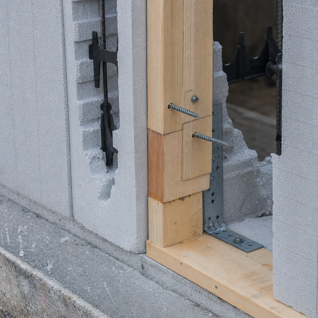
Securing window and door bucks to ICF (Insulating Concrete Form) wall assemblies requires an explicit approach to fastener specification, embedment, and dimensioning per the National Building Code - 2019 Alberta Edition (NBC(AE) 2019), particularly Part 9. Overlooking these details often results in plan-review redlines for missing or noncompliant anchorage, especially in regions with fluctuating wind loads like southern Alberta.
Code-Driven Fastener Type, Size, and Layout
Table 9.27.5.4.-B of NBC(AE) prescribes fastener diameters and spacing for claddings attached to flat wall ICFs, but the principles extend to reinforcing the inside perimeter of the ICF opening:
- Wood Trim: Minimum 3.5 mm screw diameter. Max 400 mm or 450 mm horizontal on-centre spacing, depending on web fastening strips.
- Lumber or Horizontal Siding: Minimum 4.2 mm screw diameter. Max 400 mm or 450 mm o.c.
- Metal Cladding: 4.2 mm min, same spacing.
- Vinyl Cladding: 3.5 mm min, 400 mm or 450 mm o.c.
- Panel- or Sheet-Type Cladding (≤7 mm): 3.5 mm min, 150 mm or 200 mm o.c. at edges.
- Panel- or Sheet-Type Cladding (>7 mm): 4.2 mm min, 300 mm or 400 mm o.c. at intermediate supports.
For all these, NBC(AE) 9.27.5.7. demands fasteners penetrate at least 6 mm through the web strip, or through the base, or to specific depths (19 mm for shakes/shingles, 32 mm for vinyl).
Common code checklists and review comments on plan sets include:
- “Provide specific fastener diameters, spacing, and embedment in note and detail call-outs-reference NBC(AE) 9.27.5.4.-B.”
- “Dimension fastener locations relative to window/door buck internal corners.”
- “Add detail section showing screw embedment into the concrete or approved foam web.”
Drawing-Sheet Standards: Call-Outs and Dimensional Conventions
Detail sheets must:
- Reference ‘See Detail X/A6.2 - WINDOW BUCK ANCHORAGE IN ICF’ at each opening.
- Label fastener schedules directly on detail (e.g., “#10 x 4” hex head structural screw @ 400 mm o.c. min, min embedment through plastic web strip 6 mm per NBC(AE) 9.27.5.7.”).
- Dimension edge distances to avoid splitting or insufficient embedment, e.g., “Min 25 mm from buck edge to fastener centre.”
Material notes should explicitly state “Anchorage per Table 9.27.5.4.-B, Screws hot-dip galvanized or stainless; all hardware compatible with preservative-treated wood per CSA O80.”
Field and Permit Review Nuances
Inspectors and plan reviewers scrutinize rough opening fastener call-outs in ICF jobs, anticipating practical issues such as:
- Lack of continuous anchorage (buck “floating” or bowing out after pour).
- Incorrect fastener type (“Confirm #10 SDS screws, not drywall screws, @ each web tie; see redline”).
- Omitted reference to minimum web embedment (leads to unapproved substitutions on site and RFI delays).
Omitting these conventions causes delays, costly change orders, or, at worst, failures of window or door attachment after concrete placement and curing.
Integrated Air Barrier, Weather Resistive Barrier, and Flashing Details at the ICF Wall-Buck Junction (ABC 9.27.3.2 & 9.36 Energy Efficiency Compliance)
Moisture and air infiltration at window and door openings through ICF assemblies present critical risks to building envelope continuity, thermal performance, and long-term durability-especially in Alberta’s freeze/thaw and wind-driven rain climates. The Alberta Building Code codifies these junction requirements in ABC 2023 9.27.3.2 (flashing), 9.36.2.9 (air barrier), and 9.36.2.10 (weather barrier), each demanding clear detail annotation at every opening.
Section View Detailing for Barrier Continuity
Standard practice involves full-section views through head, jamb, and sill, with direct referencing such as “See Section 6/A7.1.” Typical detail call-outs read:
- “Self-adhered AVB membrane, min. 150 mm (6”) vertical up ICF rough opening, continuous onto window/door buck and lapped min. 25 mm under window flange (per ABC 9.36.2.9/2.10).”
- “Pre-bent metal head flashing, hemmed edge, min. 50 mm vertical leg behind WRB, extend min. 25 mm past window jamb ROI, sealed to AVB membrane.”
- “WRB membrane lapped shingle-style over head/jamb/sill flashings, terminated with compatible sealant bead.”
Drawing Sheet Conventions and Material Notation
Key plan set note conventions:
- Delinate air barrier as a dashed, coloured, or thickened line in all envelope sections.
- “Head/side flashings: prefinished 24 ga. aluminum or 26 ga. galvanized steel as per finish schedule.”
- “Sealant: high-performance, elastomeric, compatible with both WRB and ICF foam (e.g., Tremco Dymonic 100 or equal).”
Material indices further clarify: “WRB: self-adhered or fully-adhered system with air permeance ≤ 0.02 L/(s·m2) @ 75 Pa per ASTM E2178 and NBC(AE) 9.36.2.9.”
Plan Review and Jobsite Issues
- Barrier discontinuity is the most common redline: “Demonstrate continuity of AVB and WRB at opening-revised detail required.”
- Improper shingle lap of membranes: “Revise head flashing detail; WRB must overlap flashing by 25 mm min per 9.27.3.2.”
- Membrane incompatibility: “Specify tested AVB/WRB/membrane system for use with ICF foam-no generic ‘polyethylene film’.”
On site, deficiencies frequently prompt call-outs such as “Incomplete air barrier overlap at rough opening-add membrane tape and request inspection.”
Flashing Geometry and Minimum Extensions
- Head flashing: extend 25 mm (1”) horizontally past both jambs, 50 mm (2”) vertically behind WRB. Sill pan or backdam min. 6 mm (1/4”) upturn.
- All fastener penetrations through air/WRB to be gasketed or sealed per manufacturer/system specification.
Failure to document these details-in note, symbol, and section-invites costly callbacks, envelope failures, or permit denials.
Rough Opening Calculation, Buck Material Specifications, and Treated Lumber Requirements for ICF Wall Applications (ABC 9.3.2.9 & 9.23.2.8)
Accurate rough opening (RO) calculation and buck material selection are foundational to both code compliance and constructability in Alberta’s ICF projects. NBC(AE) 9.3.2.9 and 9.23.2.8 provide the only acceptable minimums for decay resistance and use of pressure-treated wood. Redlines for missing or ambiguous RO and PT notes are among the most frequent under Building Permit review.
Rough Opening (RO) Calculation Conventions
- Always reference actual window/door frame dimensions (unit size from manufacturer).
- For a fixed window labelled “48x60,” with buck thickness 1.5” both sides:
- RO Width: 48" + 2 × 1.5” = 51”
- RO Height: 60" + 2 × 1.5” = 63”
- Add 1/2” clearance total (or as required by window mfr.) to facilitate shimming and air/vapour barrier continuity.
- For a fixed window labelled “48x60,” with buck thickness 1.5” both sides:
- Drawing notation example: “RO for Window Type W201: 51.5” W x 63.5” H, including 1.5” PT buck each side & 13 mm shim clearance all around.”
Buck Material Specifications and Drawing-Sheet Standards
- PT (pressure-treated) dimensional lumber is the default for decayed/vapour-exposed locations (see NBC(AE) 9.3.2.9(3) and 9.23.2.2/9.23.2.3).
- Drawing call-out: “PT 2x10 rough buck, preservative-treated SYP, conforming CSA O80, Use Category UC4A, per NBC(AE) 9.3.2.9(3).”
- Cross-reference note: “All exterior bucks below grade/at grade to be PT lumber per ABC 9.3.2.9 & 9.23.2.8.”
- EPS or composite bucks
- Detail call-out: “EPS buck, 1.5" thick, min. 16 psi compressive strength, solid core, mechanically braced @ 450 mm o.c.”
Buck bracing, especially for large or tall openings, is critical. Drawing detail should state: “Cross-brace PT bucks @ 457 mm (18”) o.c. temporarily during pour-removable after concrete cure.”
Code-Mandated Treated Lumber Requirements
- All wood elements less than 150 mm above grade (NBC(AE) 9.3.2.9(3)), or in contact with concrete at or below grade (9.23.2.2), must be preservative-treated, or separated by 0.05 mm polyethylene if not treated (9.23.2.3).
- Legend note: “Hatch ‘PT’ in section-see legend: Pressure-Treated Lumber, CSA O80, where in contact with concrete or within 150 mm of grade, per ABC 9.3.2.9 & 9.23.2.2.”
Redline and RFI Triggers
- “Clarify PT lumber at all window and door bucks below grade-see Section 9.3.2.9(3).”
- “Show air space or separation at wood-concrete interface, or upgrade to PT.”
- “Indicate buck thickness and add note re: shim space to clarify finished RO.”
Risking omissions here guarantees delay-untreated wood, ambiguous buck thicknesses, or non-conforming separation details are all favourites of both Building Safety authorities and municipal inspectors.
Firestopping and Fire-Separation Detailing for Buck Assemblies in Proximity to Fire-Rated ICF Walls or Assemblies (ABC 9.10.9.1 & 9.10.13.1)
The interplay between buck assemblies and fire-rated ICF walls is a source of scrutiny in multifamily, row housing, or any occupancy close to property lines. Alberta Building Code (NBC(AE) 2023) Part 9.10 requires tested details-unbroken fire stops and closures-to prevent fire migration, especially at wall penetrations and changes in construction type at opening perimeters.
Required Fire Stop Locations and Construction
- “Fire stops continuous at head, jamb, and sill buck - see 12.7 mm Type X GWB or 38 mm lumber inset in foam per 9.10.9.1(2).”
- “Fill concealed spaces with mineral wool or tight-packed fire stop foam in addition to GWB where void is >40 mm deep.”
- Window/door unit must not degrade fire rating at wall interface-draw sectional note: “Maintain min. 45 min fire-protection rating for closure at opening per 9.10.13.1(1).”
Drawing Conventions and Detailing
- Fire stop detail call-outs: “12.7 mm Type X GWB fire stop @ buck perimeter-label as ‘FIRE STOP, CONT. EACH SIDE OF BUCK, SEE DETAIL 12/A8.3.’”
- Material note: “Apply 300 mm width, 0.38 mm galv. steel sheet fire stop @ concealed joint, all sides.”
- Plan legend: shaded region = “Fire stop location per 9.10.9.6 and 9.10.16.3.”
Common Plan Review and Field Issues
- “Incomplete fire stop detail-enclose all voids between buck and ICF with Type X GWB or steel as per 9.10.9.1.”
- Combustible electrical boxes penetrating buck in rated assembly require gyp enclosure or fill: “Show noncombustible insulation or fire stop box fill (refer Medicine Hat SC Bulletin).”
- Closures at openings must retain same fire-resistance as surrounding wall: “Revise detail & note to indicate tested closure at ICF opening.”
Penetration Sealing and Third-Party Approvals
- All through-wall penetrations (e.g., pipes, vents) in a fire-rated ICF opening-seal with tested fire stop product, with listing number noted (“e.g., Hilti FS-One Max or equal-UL Assembly W-L-2267”).
- Inspection note: “No unsealed penetrations visible at buck interface-field verify after window/door install.”
Painstaking annotation, including specific section and detail bubbles, along with referenced material specifications and closure systems, is essential for a frictionless permit process-and to support future code-required maintenance and testing.
Common Plan Review Redlines and Jobsite Call-Outs Pertaining to Non-Compliant Window/Door Buck Details in Alberta (Drawing Revisions & RFI Resolution)
Buck details for ICF windows and doors remain among the top problem areas for plan review redlines and jobsite inspection failures in Alberta. The root cause is consistently lack of detail in drawings, improper material or fastener calls, and failure to explicitly show code-required barrier integration. Typical permit reviewers reference code sections in their comments, and site crews escalate ambiguous drawings via RFI, both creating project churn and costly delays.
Most Frequent Plan-Review and Field Inspection Comments
- “Provide structural calculations or specify buck materials and fastening methods to demonstrate adequate support for window/door assembly as per NBC(AE) 2023, Article 9.7.6.1.”
- “Detail the integration of window/door bucks with the WRB to ensure a continuous air and water barrier, in accordance with NBC(AE) 2023, Article 9.27.3.8.”
- “Specify decay-resistant materials for window/door bucks as required by NBC(AE) 2023, Article 9.3.2.9.”
- “Provide fastening details for window/door bucks, ensuring compliance with NBC(AE) 2023, Article 9.23.3.4.”
Each reflects tight connection to code article numbers-where ambiguity exists, plan reviewers will default to the strictest interpretation. Always respond to RFI with annotated markups linking to detail sections (“Refer 2/A6.2 for buck sash anchorage and WRB integration-now crosshatched in blue”).
Drawing Details that Succeed Under Scrutiny
- Material Specification: “Treated 2x6 Wood Buck, S4S, PT to CSA O80, Use Cat. UC4A.” Supported in plan’s “Wood Treatment Requirements” note block.
- Fastening: “(3) #10 x 4” Simpson Strong-Drive SDS screws each side, 406 mm o.c., through buck into ICF web strip to depth 32 mm.”
- Barriers & Flashing: “WRB continuous lap over head/jamb/sill, self-adhered AVB at transition; 24 ga. prefinished flashing with hemmed drip, extend past jambs per detail.”
- Sill Detail: “16 mm plywood backdam, upturned 6 mm, PT shims each side, sealed to AVB with polyether sealant.”
Dimension, Rating, and Material Best Practice
- RO Dimensions: “All window & door ROs include 1.5” buck both sides plus 13 mm shim; see Schedule A. Confirm final mfr. requirements prior to rough-in.”
- PT Rating: “All PT wood to CSA O80, treated to UC4A for exterior/ground contact.”
- Fastener Corrosion Resistance: “All fasteners through/near AVB, WRB and ICF foam to be stainless or hot-dip galvanized; bi-metal prohibited at aluminum-clad units.”
- Flashing Material: “Self-adhered butyl, min. 0.9 mm thickness; prefinished steel, min. 26 ga.; or approved substitute.”
Incorporating manufacturer literature, clear code references, and explicit dimensions on construction sheets eliminates most rounds of redline and minimizes RFI churn post-permit. Plan checkers cite best practice from guides such as CSA A440.4-2018 (fenestration installation) and expect cross-reference notes.
Failing to provide detail at these intersections-where structural, envelope, and fire safety meet-yields indefinite rounds of “Revise and re-submit” memos, or worse, on-site reconstruction with delayed occupancy sign-off.
Conclusion
Window and door buck detailing within ICF wall assemblies is a code-critical intersection of structural support, air/moisture/fire barrier continuity, and material compatibility under Alberta’s regulatory regime. The detail sheet-not general notes or schedules-must meet every code clause, from NBC(AE) 9.27.5.4.-B’s fastener matrix to 9.3.2.9’s decay resistance, 9.36’s air/WRB mandates, and 9.10’s fire stop continuity at rated assemblies. Each call-out, section, and dimension must anticipate scrutiny. Jobs move to occupancy only when permit sets, redline responses, and RFI markups all reference the exact detail, code section, and material notation required by Alberta’s inspectors and review engineers. This standard underpins every ICF project completed by Kingsway Drafting & Design.