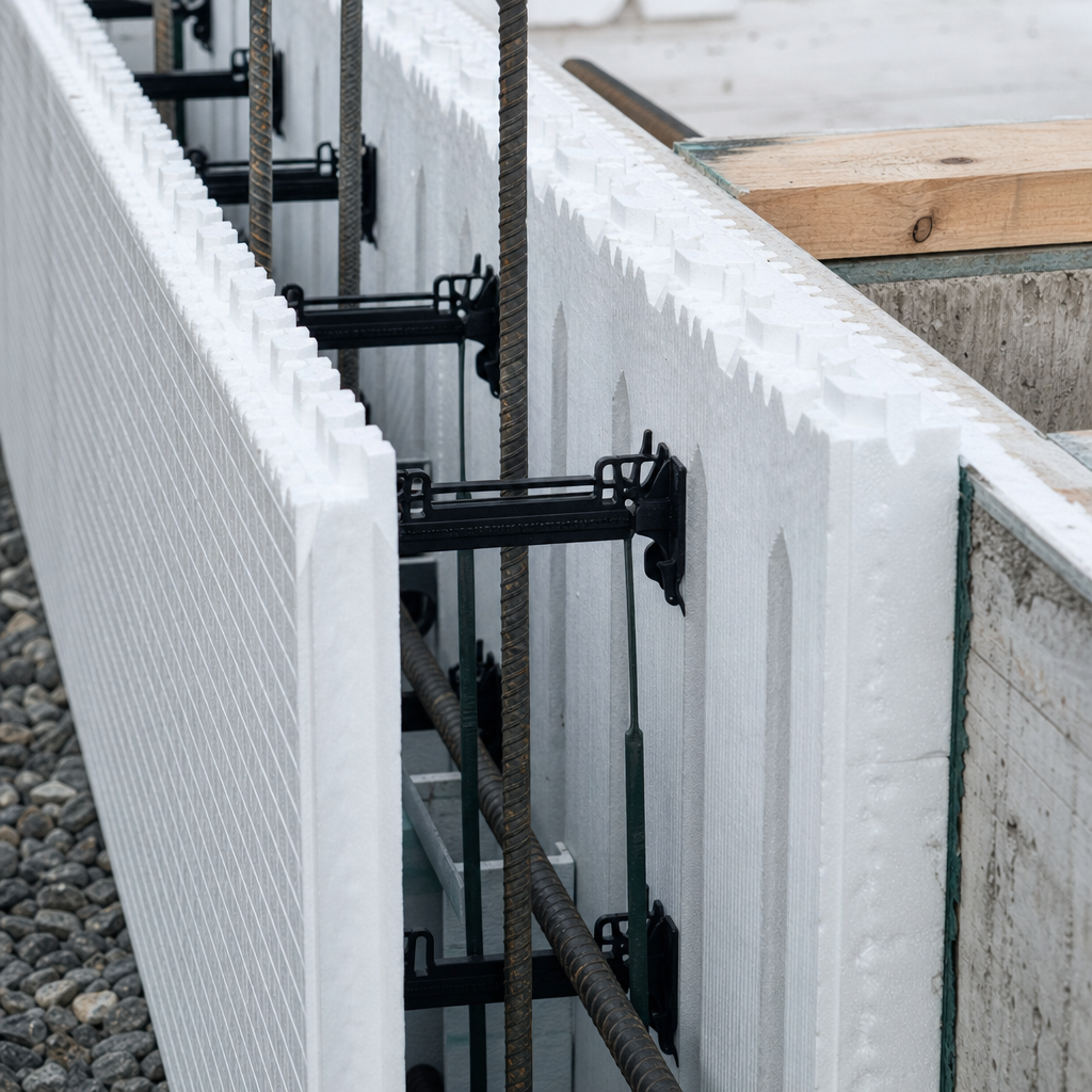
Insulated Concrete Form (ICF) construction has become a cornerstone of energy-efficient and robust basement design in Alberta. Ensuring code compliance for ICF basement walls requires rigorous attention to detail across plan sheets, section details, dimensions, code call-outs, and site construction sequences. Precision in drafting, referencing, and plan organization is critical, not only to meet Alberta Building Code (ABC) requirements but also to withstand the scrutiny of plan reviewers and the realities of the job site.
Structural & Seismic Detailing of ICF Walls per NBC(AE) Part 9
Concrete Core: Specifying Thickness, Strength, and Placement
ICF basements rely on a reinforced concrete core surrounded by EPS foam for insulation and formwork. According to NBC(AE) 2023 Section 9.15.4.1, foundation walls using flat wall ICF units must employ concrete cores not less than 150 mm in thickness, or matching the wall above if greater. Drawings must explicitly indicate the concrete core dimension, separate from overall wall thickness (which includes both insulation faces). On plan and section views, dimension lines should reference the centreline of the concrete core-calling out, for example, “150 mm MIN. CONC. CORE” or “CONC. CORE TO ALIGN WITH U/S FOAM BOTH SIDES”.
Concrete strength directly affects both structural performance and Basement code compliance. NBC(AE) Section 9.3.4.2 prescribes a minimum compressive strength; typical Alberta practice is 25 MPa at 28 days for residential foundations, with a slump of 100 mm ±20 mm for pump-placed ICF work. Drawings and general notes must specify: “CAST-IN-PLACE CONCRETE: f’c = 25 MPa @ 28 DAYS, SLUMP = 100 mm, AIR-ENTRAINED 5-8%”. This is a common plan-review redline if omitted or if mix requirements are ambiguous.
Rebar Detailing-Schedules, Lap Lengths, and Critical Locations
Well-documented rebar placement is an absolute necessity for permit approval and site success. All reinforcement design, including dowels, bar sizes, lap lengths, and spacing, must be visible in plans, sections, and in a separate rebar schedule-avoid generic “as required” notes, which will be flagged during plan review.
- Per NBC(AE) 9.3.1.1 and CSA G30.18:9, 10M bars require a minimum lap splice of 450 mm, 15M bars require 650 mm. Plan redlines frequently target undersized laps or undocumented laps, especially at vertical bar splices and around window/door openings. Drawing note: “10M REBAR: MIN. 450 mm LAP; 15M REBAR: MIN. 650 mm LAP PER NBC(AE) 9.3.1.1”.
- Place vertical bars no more than 600 mm o.c.; exact spacing and location at corners/openings must be dimensioned. For “flat-wall” ICF, annotate: “VERT. 10M @ 400 mm o.c., STAGGER AS SHOWN IN DETAIL 2/S502”.
- Complex conditions (corners, large openings, point loads) may shift reinforcement design to a Part 4 engineered solution-clearly call out “DETAIL TO BE DESIGNED BY STRUCTURAL ENGINEER” where prescriptive Part 9 cannot be met.
- For window and door openings, document “ADDITIONAL 10M HORIZ. BAR TOP/BOTTOM OF OPENING, VERT. BARS BOTH SIDES, 450 mm LAP”, referencing enlarged details on additional sheets.
Bar-bending diagrams (plan/section call-outs and included schedule) must explicitly show how horizontal bars turn corners (“10M CONT. AROUND CORNER, BEND TO MAINTAIN 450 mm LAP EACH LEG”) and are placed above/below openings. Lack of clarity here is routinely caught by plan reviewers, who often note “INSUFFICIENT REBAR DETAIL AROUND OPENINGS” or “PROVIDE REBAR BENDING, TIE LOCATIONS, AND LAP LENGTHS FOR ALL CORNERS AND OPENINGS”.
Form Ties, Cold Joints, and Structural Sequencing
Form ties are inherent to ICF block systems and critical for concrete placement pressure management. Form tie spacing isn’t directly mandated by code but by the ICF manufacturer, so on drawings and notes, explicitly specify “FORM TIE SPACING AS PER MANUFACTURER’S LATEST PUBLISHED INSTALLATION GUIDE”. For tall walls or multi-lift pours, show the location and sequencing of ties with a leader note-“TIES TO BE INSTALLED AT 400 mm HORIZ, 600 mm VERT SPACING, TYP.”-unless otherwise specified.
Cold joints-where fresh concrete butts against previously cured pours-must be anticipated and detailed. Indicate joint location in section details (usually at floor level or top-of-wall pour breaks), call out surface prep and bonding requirements. Note: “COLD JOINT: ROUGHEN SURFACE, CLEAN, APPLY APPROVED BONDING AGENT, CONTINUOUS REINFORCEMENT THROUGH JOINT”. Alberta plan review regularly flags missing cold joint detailing, marking “PROVIDE SPECIFIC COLD JOINT DETAIL AT SLAB-TO-WALL INTERFACE AND AT MULTI-LIFT ICF POURS”.
Example Structural Plan-Review Comments and Sheet Notations
- “NO CONCRETE STRENGTH SPECIFIED FOR ICF WALLS-ADD 25 MPa, 100 mm SLUMP TO GENERAL NOTES.”
- “REBAR SCHEDULE IS INCOMPLETE-MISSING LAP LENGTHS AT WINDOW OPENINGS.”
- “ICF MANUFACTURER’S TIE SPACING DETAIL REQD-CALL OUT IN SECTION AND PLAN NOTES.”
- Detail bubble: “SEE TYPICAL CORNER REBAR LAYUP, DETAIL 4/S503”.
ABEC Part 9.36 Compliance and Thermal Detailing for ICF Basements
Effective R-Value Calculations and Plan Documentation
Section 9.36 of the Alberta Building Code sets minimum effective thermal resistance requirements for foundation assemblies in Climate Zone 7A-critical for ICF foundations. The effective value for foundation walls is RSI 2.98 (R-16.9). Drafted sets must underscore both the effective R-value and the assembly construction in wall schedules, wall sections, and general notes. Annotate all assemblies with a detail note: “ICF FOUNDATION WALL ASSEMBLY: RSI 3.0 (R-17.0) EFFECTIVE ASSEMBLY PER ABEC 9.36.2.8”.
ICF system performance must account for both the EPS layers and the concrete core, adjusted for any internal bridging (such as ties or bucks)-using third-party test data if claimed values are used, or CSA/industry published tables. Many plan reviewers highlight “EFFECTIVE R-VALUE IS UNDOCUMENTED OR NOT SHOWN-ADD TO FOUNDATION AND WALL SCHEDULES”.
Continuous Insulation and Air Barrier Detailing
Wall assemblies must be thermally and airtight from footing through to top of wall and at all penetrations:
- Sill Plate Transitions: Section details should show a continuous insulation line from the ICF EPS through the end-grain of the sill plate, using a rigid foam “thermal break” or sill gasket. Callout: “CONT. RIGID INSULATION UNDER SILL PLATE; FOAM SEAL ALL EDGES-SEE DETAIL 3/A503”. This is a frequent review redline if omitted.
- Penetrations: All pipes or conduit through the ICF wall must be sealed with both foam and air barrier membrane. Section detail annotation: “ICF PENETRATION: SLEEVE THROUGH CORE, FOAM PACK, CONTINUOUS MEMBRANE OVER, TAPE EDGES”. On plan and elevation, reference to penetration schedule or “SEE TYP. PENETRATION DETAIL 8/S705”.
- Air Barrier Strategy: Detail must depict an uninterrupted air barrier line (often a dashed line in detail view) from the ICF foam to the main floor air barrier membrane or up the exterior wall. Note: “CONT. SELF-ADHERED AIR BARRIER-BOND TO ICF EPS PER ABEC 9.36.2.9”.
Mitigating Thermal Bridging at Slab, Sill, and Above-Grade Transitions
ICF/Slab Interfaces: Show minimum 50 mm (2") extruded polystyrene (XPS) slab-edge insulation extending from slab underside to bottom of sill plate, returning along the ICF foam. Heavy plan reviewer emphasis is placed on “SLAB EDGE INSULATION”, commonly commented as “THERMAL BRIDGE AT SLAB EDGE-PROVIDE R-7.5 (RSI 1.3) INSULATION, DETAIL ALL EDGES”. Drawing note: “XPS RIGID (50 mm) INSULATION CONT. FROM SLAB EDGE TO SILL, TYP. - SEAL ALL JOINTS”.
Above-Grade Walls: Maintain continuous insulation up the entire ICF core to the main floor and any above-grade portions. For walkout basements, call out foam continuity in both section and elevation: “ICF WALL INSULATION TO BE CONTINUOUS FROM FOOTING TO PLATE/MAIN FLOOR”.
Plan Review and Sheet Notation Standards for Energy Detailing
- “PROVIDE CONTINUOUS AIR BARRIER LINE ON SECTIONS AND DETAILS, INCLUDING DASHED LEGEND KEY.”
- Wall schedule must assign every wall an effective RSI or R-value with reference to ABEC 9.36 subsection- e.g. “W1 = ICF BASEMENT, RSI 3.0 EFFECTIVE PER 9.36.2.8”.
- Insulation call-outs: “R-17.0 ICF WALL ASSEMBLY, CODE MIN. MET OR EXCEEDED-SEE THERMAL SCHEDULE.”
Waterproofing, Drainage, and Backfill: Detailing and Notation of Site Elements
ICF Waterproofing and Dampproofing-Material Choices and Drawing Callouts
ICF is unique for below-grade waterproofing. Section 9.13.3.1(1) of the ABC requires real waterproofing membranes wherever hydrostatic pressure is anticipated. On elevation and wall section sheets, clearly represent the sequence:
- “APPLY SELF-ADHERED MEMBRANE, 1.5 mm (60 mil) NOMINAL, COMPATIBLE WITH EPS, TYP. ALL BELOW-GRADE ICF.”
- For liquid-applied options: “WATER-BASED LIQUID MEMBRANE-COMPATIBLE WITH EPS PER ICF MANUFACTURER’S GUIDELINES, 2-3 COATS (2 mm DRY THICKNESS)”
- Label primer spec if required: “PRIMER TO BE NON-SOLVENT, AS APPROVED BY ICF BLOCK SUPPLIER.”
Protection board (extruded polystyrene, high-density plastic, or mineral wool) must shield the membrane and foam. Call out on section: “PROVIDE DRAINAGE PANEL, 10 mm MIN., OVER WATERPROOFING”. During construction, this sequencing note should be echoed as: “NO BACKFILL UNTIL MEMBRANE AND PROTECTION BOARD ARE INSPECTED AND APPROVED”.
Footing Drainage Systems: Detailing and Specification
Section 9.14.2.1(1) of the ABC mandates full-perimeter footing drainage-every section or site plan must show continuous 100 mm (4") perforated weeping tile at the footing, enveloped in granular fill. Notation hierarchy:
- Plan view: “4" PERF. PIPE (CSA B182.1), SLOPE 1%, AROUND PERIMETER, CONNECT TO SUMP.”
- Section: “150 mm (6") CLEAR CRUSHED STONE ALL SIDES OF DRAIN TILE, AT FOOTING LEVEL.”
- Fabric: “FILTER FABRIC (NON-WOVEN) TO ENVELOPE GRAVEL AND PIPE, TYPICAL.”
Many plan reviewers note: “MISSING FILTER FABRIC DETAIL AT DRAIN TILE-PROVIDE.” and “GRAVEL COVERAGE AT PIPE INSUFFICIENT-SHOW 150 mm COVER ALL SIDES”. Site instructions should reinforce “WEIGHT OF BACKFILL EQUIPMENT TO BE KEPT 1200 mm MIN. FROM FOUNDATION EDGE UNTIL BACKFILL SETTLES”.
Backfill and Grade Detailing Per ABC
Proper grade and backfill approaches are essential for durability and code compliance. Sections 9.14.3.1 through 9.14.3.4 prescribe that backfill shall be free of debris, large stones (not greater than 250 mm diameter), and pyritic materials. On section details and in site notes, specify:
- “BACKFILL: CLEAN FILL, FREE OF ORGANICS, COMPACT IN 300 mm LIFTS”
- “MAX. PARTICLE SIZE 250 mm, NO CLAY OR PYRITIC CONTENT.”
- “GRADING TO SLOPE MIN. 5% AWAY FROM FOUNDATIONS FOR FIRST 2.0 m.”
- “NO BACKFILL UNTIL 7 DAYS AFTER POUR OR AS DIRECTED BY ENGINEER.”
Failure to include these notations is a frequent reason for plan review comments: “BACKFILL AND GRADE SPECIFICATIONS MISSING-SEE ABC 9.12.3.3” and “GRADING SLOPE NOT SHOWN OR NOTED-MUST MEET 5% REQUIREMENT”.
Sheet and Detail Organization for Waterproofing, Drainage, Backfill
- Details numbered sequentially - e.g., “Detail 3/S503: Waterproofing & Drainage at ICF Wall-Footing”.
- Site/grading plan sheets must cross-reference section cuts for gradeaway and backfill (“SEE TYP. SECTION 1/A601 FOR BACKFILL & GRADE”).
ICF Intersections: Slab, Top-of-Wall, Openings, and Penetrations
ICF/Slab Interface-Keyways, Dowels, Joints, and Thermal Detailing
Precise interface details at the slab-on-grade or basement slab are vital. The plan and section must clearly illustrate:
- “38 mm (1.5") WIDE x 38 mm (1.5") DEEP KEYWAY FORMED IN FOOTING AT WALL CENTRELINE-TYP. ALL FOUNDATIONS.”
- “10M REBAR DOWELS @ 400 mm o.c., L=600 mm, EMBED 300 mm IN FOOTING, 300 mm IN WALL.”-Dimension as required by NBC(AE) 9.15.4.3 and engineering.
- “POLYETHYLENE VAPOUR BARRIER (6 MIL) LAP & SEAL AT EDGES, RUN TO ICF WALL FOAM”
- “SLAB EDGE INSULATION-50 mm XPS CONTINUOUS, RETURNED VERTICALLY ALONG ICF FOAM”
Cold joints at wall/slab interfaces must be specifically treated (“APPLY BONDING AGENT AT COLD JOINT, CONTINUE ALL VERTICAL BARS”), with location and treatment called out on every typical section. It is a recurring plan review note that missing keyway or dowel dimensions will trigger a redline: “PROVIDE SLAB DOWEL AND KEYWAY DIMENSIONS AND SPACING AT ALL TYPICAL LOCATIONS”.
Main Floor Anchorage and Ledger/Bearing Details
Connection of ICF walls to above-grade framing is governed by NBC(AE) 9.15.5:
- Detail and plan call for “12.7 mm Ø HOT-DIP GALVANIZED ANCHOR BOLTS, EMBED 100 mm MIN. @ 2.4 m MAX. O.C., 300 mm FROM ALL ENDS”-shown in anchor bolt schedule, referenced on both plan and section detail. Marked on sheet as: “SEE ANCHOR BOLT SCHEDULE S901”.
- Sill plate detail sequence: “25 mm SILL GASKET BETWEEN PT SILL PLATE AND ICF FOAM, CONT. ALL SIDES”-which is reviewed for both thermal and air leakage compliance.
- Ledger boards or beam pockets are drafted with both material spec (PT wood, or engineered lumber) and dimension: “LEDGER: (2) 2x10 SPF #2, 150 mm EMBED, FASTEN PER STRUCTURAL, SEE DETAIL 6/S507”.
- Beam pocket notation: “FORM BEAM POCKET WITH 10 mm FOAM LINING, ALLOW 6 mm CLEARANCE AND 19 mm SLEEPER BELOW”-compliant with both fire and structural requirements.
Common plan review notes at this stage: “ANCHOR BOLT O.C. EXCEEDS 2.4 m, INCREASE QUANTITY” and “NO SILL GASKET SHOWN, PROVIDE CONTINUOUS SEAL”.
Openings and Penetrations-Framing, Reinforcement, and Air/Vapour Integrity
- Windows/Doors: Each opening is boxed with a prescriptive or engineered buck (i.e., “PT LUMBER BUCK, 38x140 mm, ANCHOR TO ICF TIES @ 400 mm O.C.”). All schedules reference Detail 5/S603 for typical window framing with note: “PROVIDE 2x10 HEADER ABOVE WINDOW, 200 mm MIN. END BEARING. CLOSE ALL EPS, FOAM SEAL TO ICF.” Rebar call-out: “ADDL. 10M BAR ABOVE AND BELOW ALL OPENINGS, LAP PER S902”
- Utility Sleeves: “PVC SLEEVE, DIA. + 13 mm CLEAR, SET AT POUR, FOAM PACK AFTER PENETRATION, SEAL WITH COMPATIBLE AIR BARRIER TAPE-TYPICAL FOR ALL PIPES/ELEC.”. Reference on set as “SEE TYP. UTILITY PENETRATION, DETAIL 8/S705”. Each must have its location, size, and finish specified in a penetration schedule.
- Firestopping: For fire-resistive assemblies and required separations, every penetration must call out “FIRESTOP MATERIAL ULC S115 LISTED, F RATING EQUAL OR GREATER THAN WALL ASSEMBLY, FOAM SEAL OUTSIDE OF PENETRATION.”
Airtightness Callouts and Review Comments
- On the sheet: dashed air barrier trace with leader: “CONT. AIR BARRIER-MEMBRANE TAPED AT ALL TRANSITIONS, SEAL TO SILL AND AT ALL OPENINGS, PER 9.36.2.9”.
- Common comments: “MISSING FOAM SEAL AROUND WINDOW BUCK-ADD TO ALL OPENING DETAILS”, “PENETRATION NOT SEALED TO AIR BARRIER-SHOW DETAIL AND MATERIAL SPEC”.
Dimensioning, Notation, and Plan Set Sheet Mechanics for ICF Projects
ICF-Specific Dimensioning Protocols: Core vs. Overall Thickness
All ICF plan sheets must dimension to the concrete core-never the outside face of foam. For a typical ICF wall with a 150 mm core and two 67 mm foam panels, all wall centerline dimensions and gridlines align to the core center. Plan view annotation:
- “ALL DIMENSIONS TO CONC. CORE CL UNLESS NOTED. SEE SECTION A/A502 FOR WALL BUILD-UP.”
- “TOTAL WALL THICKNESS = 285 mm (150 mm CONC. CORE + 2x67 mm EPS), SEE WALL SCHEDULE.”
Window/door openings are dimensioned to core edges. Section detail always shows-“150 mm CONC. + 67 mm EPS/EA SIDE, 285 mm O/A”, with material key and schedule lookup. This is a frequent correction on submitted sets: “OPENING DIMENSIONED TO OUTSIDE FOAM-CORRECT TO CONC. CORE”.
Leader Lines, Notes, and Drawing-Sheet Communication
- All critical actions and sequences must be enumerated in numbered leader lines:
- “1 - STACK ICF BLOCK TO LEVEL SHOWN”
- “2 - INSTALL REINFORCEMENT PER SCHEDULE”
- “3 - POUR CONCRETE IN 1.2 m LIFTS, CONSOLIDATE W/ VIBRATOR”
- “4 - SET DOWELS AND SLEEVES PRIOR TO FINAL POUR”
- Material notes must link to a specification: “EPS - TYPE 2 TO CAN/ULC-S701.1, 67 mm NOMINAL”.
- Each wall assembly references its code compliance: “ICF WALL ‘W-1’: ABEC 9.36.2.8, RSI 3.0, 1-HR FIRE-RATING TO ABC 3.1.7.1”.
Leader lines from notes should point to the actual component, and where spatial clarity is at risk (complex intersections, change in plane), employ both text and key-legend codes cross-referenced to details (“SEE DETAIL 7/S606 FOR ICF WALL-TO-SLAB JUNCTION”).
Sheet Organization and ICF Detail Libraries
ICF-related details should appear in a dedicated “WALLS AND DETAILS” sheet series (e.g., S500-S599), while wall schedules and rebar schedules are isolated for easy checking by contractors and reviewers. Typical organization:
- S500: Standard ICF Sections (Slab, Top-of-Wall, Typical Reinforcing)
- S601-S609: Openings, Corners, Penetrations, and Special Connections
- S700: Schedule-Wall Types, R-Value, and Assembly Composition
- S900: Reinforcement Schedules and Anchor Bolt Layouts
Developing a robust detail library is essential; standardized, pre-reviewed details allow drafters to “drop in” ICF assemblies with proven compliance. Each detail should be accompanied by the latest code reference, material specs, and sequence numbering. For example:
- “DETAIL 3/S503: ICF WALL-TO-SLAB DETAIL: 150 mm CONC. CORE, 67 mm EPS/EA SIDE, 10M @ 400 mm O.C. VERT., DOWELS @ 600 mm, SILL PLATE GASKET, TYP. AIR BARRIER CONTINUITY.”
- “DETAIL 5/S601: WINDOW OPENING IN ICF, PT BUCK, ADDL. 10M BAR ABOVE/BELOW, FOAM SEAL ALL GAPS.”
Errors arising from inconsistent detail referencing, ambiguous dimensions, or missing specifications are significantly reduced by library use-plan reviewers respond favorably to sets that demonstrate a coherent, tested standard, noting “STANDARDIZED, COMPLETE, AND CLEAR-EASES REVIEW”. A detail key on the cover sheet further aids navigation.
Material Specifications and Code References: Best Practices
- Call out concrete: “CAST-IN-PLACE 25 MPa, AIR-ENTRAINED, SLUMP 100 mm, CSA A23.1.”
- EPS foam: “TYPE 2 EPS TO CAN/ULC-S701.1, 2.625” (67 mm) EACH FACE, O/A WALL 11.25” (285 mm).”
- Reinforcement: “10M, 15M REBAR TO CSA G30.18, Fy = 400 MPa.”
- Air/vapour: “6 MIL POLY, LAPPED 150 mm, SEALED TO ICF FOAM.”
- Reference all critical practices to code section: “PER NBC(AE) 9.15.4.1”, “PER ABEC 9.36.2.5”.
Boilerplate notes at the start of every section/sheet reinforce code intentions and sequencing; for example: “READ THESE NOTES IN CONJUNCTION WITH ALL TYPICAL DETAILS S500-S599. NO SUBSTITUTIONS OR DEVIATIONS WITHOUT WRITTEN APPROVAL OF THE DESIGN PROFESSIONAL AND LOCAL AUTHORITY HAVING JURISDICTION.”
Minimizing Plan-Review Redlines and Field Errors
Nearly all plan-review comments for ICF basements can be traced to missing or ambiguous information-lap lengths, anchorage location, unclear insulation transitions, incomplete air barrier lines, or unreferenced material/assembly specs. Drawing sets that fix dimensions to the concrete core, label R-values, detail all critical sequences, and provide explicit cross-references to code sections move through the approval process faster and with fewer revisions. Typical redline callouts include:
- “CORE DIMENSIONS NOT SHOWN-PROVIDE.”
- “REINFORCEMENT AND LAP LENGTHS AT OPENINGS INSUFFICIENTLY DETAILED.”
- “INSULATION OR AIR BARRIER DISCONTINUITY-PROVIDE DETAILS OF CONTINUOUS ENVELOPE.”
- “DRYLOK MEMBRANE SPEC INCOMPATIBLE WITH EPS-VERIFY AND PROVIDE COMPATIBLE SYSTEM.”
Field errors-such as omitted sleeves, misaligned bucks, or insufficient reinforcement-are curtailed by drawing sets that strictly enumerate material types, dimensions, and installation sequencing with graphical clarity. Use of industry-vetted detail libraries and schedule keys further streamlines both plan review and trade comprehension.
By integrating precise dimensioning, thorough code call-outs, robust material schedules, and cross-referenced detail libraries, Alberta ICF drafting achieves structural and thermal performance, jobsite clarity, and smooth regulatory approval. For comprehensive, code-compliant ICF design documents in Calgary and beyond, Kingsway Drafting & Design delivers technical accuracy at every detail.