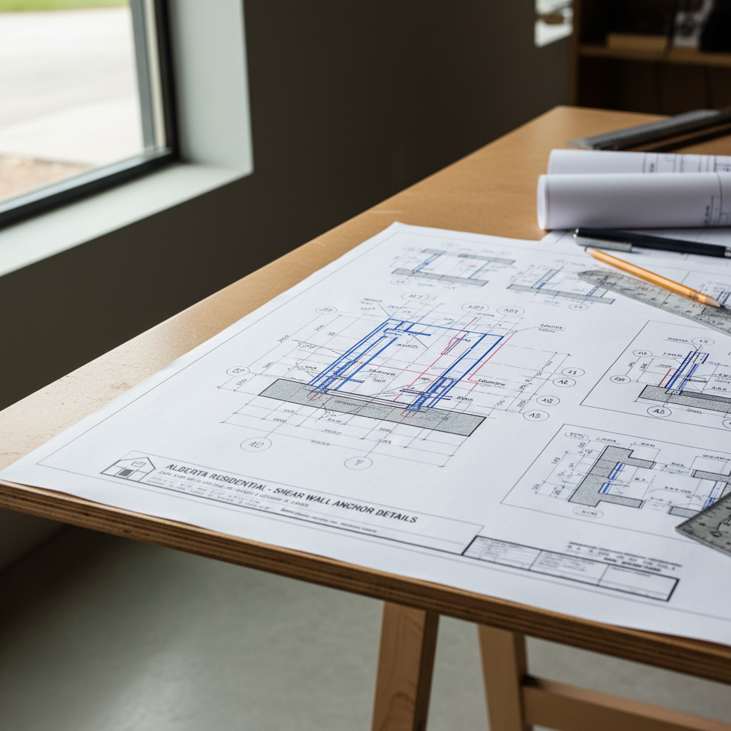
Robust lateral resistance in low-rise wood frame construction starts with the precise anchorage of shear walls and foundations. Lateral loads from wind and seismic events place immense stresses on walls and their interface with foundations. When hold-downs, anchor bolts, and related connectors are omitted, under-detailed, or mis-installed, the result is often excessive deflection, uplift, or even catastrophic failure at the wall-foundation interface. The National Building Code - 2023 Alberta Edition (NBC(AE) 2023) codifies the minimum requirements for these vital connections, but achieving true reliability in the field requires nuance far beyond the codebook page.
Anchoring Building Frames per NBC(AE) 2023 Article 9.23.6.1
Alberta code requires all building frames-unless a rigourous structural analysis proves otherwise-to be positively anchored to their foundations. Details can involve either embedding framing (such as the first floor joists) into concrete or, far more commonly in wood frame housing, mechanically fastening the treated bottom (sill) plate to the concrete or masonry foundation using anchors.
Code-Specified Anchor Bolt Size and Spacing
- Minimum diameter: 12.7 mm (1/2 inch)
- Maximum spacing: 2.4 m (8 ft) on centre
- Minimum embedment: 100 mm (4 in) in concrete/masonry
- End-of-plate placement: within 300 mm (12 in) from ends of wood plate runs
Drafting these details involves more than specifying “anchor bolts at 8’-0” o.c.” Drafters must ensure that these requirements translate meaningfully to the shop and site; for example, a plate may terminate between two anchor bolts. The drafter must confirm an anchor is placed appropriately close to the end to prevent the plate from splitting or being insufficiently anchored, while allowing room for proper tightening of nuts/washers and avoiding clash with floor framing fasteners or plumbing rough-ins. An accurate detail will include not just the anchor count or spacing, but also plans for offsetting anchors where conflicts exist (for instance, at anchor clusters where plate splices and wall terminations coincide).
Specifying Embedment-Practical Impacts on Construction
The code minimum embedment (100 mm or 4 in) can be insufficient in windy regions of Alberta such as Lethbridge-even when calculations using Part 9 loads indicate compliance. High wind/exposure areas often require greater embedment and more robust washers (even plate washers), so clear cross-referencing of wind exposure categories with structural/engineer notes is prudent.
- Consider specifying anchor bolt embedment at 150 mm (6 in) where local soil or wind/snow loading warrants enhanced anchorage.
- Annotate detail sheets to indicate where local engineering may supersede default dimensions-especially for custom homes, infill, or hillside lots.
Anchoring Exterior Columns and Posts (NBC(AE) 2023 Art. 9.23.6.2)
Open-porch columns, tall deck posts, and entrance canopies are often left under-detailed, yet are especially vulnerable to lifting and lateral sway under Alberta’s winter winds. The code prescribes anchoring all exterior columns-including those not supporting roofs, if above certain heights or sizes-against both uplift and lateral movement.
- Footing connections must positively resist uplift (from wind suction or unbalanced snow drift) as well as side-shear (due to deck lean, frost heave, or occupant loads).
- “Exception” situations (such as low platforms smaller than 10m2 and not supporting a roof) must be unambiguously marked on both site plans and detail sheets, so that building officials and site supervisors don’t overlook the difference from larger, code-compliant platforms.
- Column base anchors should be specified by make, with lateral/vertical capacity called out or fully detailed (for example, “Simpson ABU66Z with 4-12M dowels, minimum embedment 150mm, 4 timberlok screws at post base”).
Contrasting Hold-Downs and Anchorages in Shear Walls
Wood earthquake engineering evolved with the distinction between two primary forms of shear wall overturning resistance: hold-down devices vs. simple anchorages at the wall base.
- Hold-downs: Mechanical connectors (often steel brackets) installed at the ends of shear wall segments, bolted to the end stud (stud pack) and attached to the foundation or continuous tie-down anchor (such as a threaded rod embedded into concrete). The hold-down carries the entire tension demand from overturning, bypassing much of the sheathing and bottom plate.
- Anchorages: Shear wall segments without special hold-downs rely on robust anchor bolts connecting the bottom (sill) plate to the foundation or to the top plate below. In this setup, the load is transferred through both the nails connecting sheathing to plate and from the plate into the anchor bolts.
Where hold-downs are employed, their connection to the foundation must provide a continuous, direct load path for the full magnitude of tension force anticipated during wind or seismic events. Without such hardware, the designer must apply a Hold-down Effect Factor (Jhd)-typically reducing the engineering shear capacity by up to 50%, as the bottom plate and sheathing combine to form a “weak link.” This is a critical drafting step: a segment using simple anchor bolts but no hold-down connectors is not equivalent in capacity, and mis-detailing this can invalidate an entire bracing scheme.
Consequence of Device Selection on Drafted Details
- Hold-downs permit full use of published shear wall capacities for rated sheathing:
- Drafting should feature clear callouts for hold-down model, fastener pattern, and connection to concrete.
- Design note: Length and orientation of the end stud pack matter; drafters must not simply attach a hold-down to a single stud unless rated that way.
- Where anchor bolts alone are used:
- Provide a notation referencing the reduced shear capacity per manufacturer data or code-mandated Jhd factor.
- The detail must ensure anchor bolt placement supports plate and sheathing nailing patterns without excessive notching or holes.
Drafting for Practical Installation: Pitfalls and Solutions
Anchor Bolt Placement: Achieving Code and Constructability
- Coordination with wall geometry: Place anchor bolts so they miss all floor framing fasteners and rough-ins, ideally showing the offset on floor plans or wall-section sheets.
- ‘Within 300mm’ Rule at Plate Ends: Careless placement can lead to too-close bolt clusters when wall segments are short. Drafters should dimension each segment anchor explicitly on plan, especially at braced wall lines, corners, and splice plates.
- Bolts and Framing Alignment: Ensure enough clearance to tighten nuts and washers beneath sill plates-especially when using deeper engineered floor systems-by detailing the elevation offset of bolt shanks from plate edges.
A practical misstep often occurs at plate splices. If the anchor bolts are spaced purely by the maximum allowed (2.4m on centre), a plate splice at mid-span can be vulnerable to uplift or sliding where no bolt exists within 12". Explicitly call out “Anchor within 300mm of all plate ends, joints, or splices.”
Similarly, for double or triple bottom plates (used for leveling foundation irregularities), annotate the anchor to extend through all plates, with washers specified for the full plate thickness, accommodating custom plate-pack heights if needed for leveling.
Hold-Down Installation: Integrating Structural and Architectural Sheet Callouts
- Precisely locate hold-downs on plans and sections with callouts such as “HDU2 hold-down at each end of braced wall segment, within 300mm of segment end.” Show the anchor rod center and edge distances on wall base plans, and coordinate this with any embedded beam pockets or intersecting pipes.
- Specify compatible fasteners: For example, when detailing a Simpson Strong-Tie HDU2, annotate “install with minimum 8-16d nails or specified lag screws to end stud.”
- Alignment with Foundation-Recessed Hardware: Foundation anchor rods for hold-downs are often placed prior to wall erection; show accurate rod projections and orientation on both foundation plans and wall elevations. Include a note for site layout marking to avoid after-the-fact chipping, which weakens anchor integrity.
Engineered plans may show a 19 mm (3/4 in) diameter anchor rod for hold-downs. Drafters must detail the foundation top to include blockouts or form sleeves for accurate placement, noting “template set for hold-down rod, see detail X/S-1.” Failure to detail this results in expensive field fixes or non-load-path-compliant installations.
Sheathing and Nailing: From Code to High-Performance Drafting
- Sheathing thickness & rating: Drafter must refer to Table 9.23.17.2 in NBC(AE) 2023 and annotate “9.5 mm (3/8 in) min. plywood/OSB, CSA rated, blocked/unblocked edges as per plan.” For high-shear regions, specify “all panel edges blocked.”
- Panel nailing schedule: The default edge nailing is 150 mm (6 in) o.c., but for increased shear resistance, plans should show 100 mm (4 in) or even 75 mm (3 in) o.c. at panel edges. Interior nailing on 300 mm (12 in) o.c. is typical, but high wind or narrow wall segments may warrant tighter patterns.
- Detail overlap at wall ends: Drafters should ensure that sheathing terminates over full-width studs at wall ends, not over cripple studs or unsupported edges. For multi-storey projects, detail the required floor-to-floor overlap or backer blocking at wall intersections to avoid compromised shear transfer at stack joints.
Compatibility Between Foundation and Framing Trades
Conflicts often arise in the field when anchor rods (for hold-downs or bolts) interfere with mechanical penetrations, drainpipes, or even rebar. Drafter best practice:
- On foundation plans, cross-checked against the mechanical drawing(s), indicate “No anchor rods within 200mm of planned pipe penetrations-coordinate on site.”
- For slab-on-grade stems, detail anchor bolt sill elevation relative to finished floor and slab step, so that framing crews do not find rods buried beneath slab edge insulation, leading to omitted anchors or on-site non-compliant field drilling.
- On section details, call out thickened slab edges or continuous footings where hold-downs or concentrated anchor loads are present, referencing structural notes for local reinforcing where required.
Drafting to Accommodate New Code Requirements and Enhanced Performance
Energy Efficiency Criteria and the Impact on Anchorage Detailing
Recent code changes in NBC(AE) 2023 around energy tiers and exterior insulation add complexity to traditional wall-foundation interfaces. Thicker outer insulation or exterior insulated sheathing increases the distance between the structural wall frame and foundation face, challenging standard anchor bolt lengths and washer sizes. Drafters must:
- Dimension anchor bolt lengths to match the full wall assembly thickness (framing plus insulation and sheathing).
- Specify washers of sufficient diameter and thickness to bridge the gap between the structural plate and the anchorage point, using insulation compression-resistant spacers if needed.
- Show the full insulation/bolt/plate/washer “sandwich” in wall section details, calling out make, material, and installation sequence, such as “3” rigid insulation, 2x6 PWF sill plate, 1/2” anchor bolt x 12” min. embedment, 2 1/4” dia. plate washer.”
Accessibility & Universal Design: Seismic and Lateral Loading in Ramped Entryways
Updates to accessibility requirements impact the way entrances, ramps, and elevator pits are built into the foundation and framed wall system. Entry landings become special cases for anchor design:
- Where braced wall segments coincide with accessible ramps, anchor locations may be forced off center to maintain barrier-free access. Drafters should show “offset anchor bolts” and connect coordination notes referencing both the accessibility consultant and the engineer of record.
- Elevator pit walls (for residential lifts) often require enhanced vertical reinforcement and custom anchorage, which should be included in explicit, enlarged details tied to the pit's unique geometry and slab step locations.
Drafting for Real-World Alberta Applications
Wind-Belt Construction: Southern Alberta Considerations
Lethbridge, Pincher Creek, and foothills communities experience wind loads notably higher than NBC prescriptive minimums. Spins from November Chinooks to summer thunderstorm gusts create uplift and shear far exceeding standard design.
- High-exposure braced wall lines should feature closer anchor spacings-specify 1.2m or even 900mm O/C instead of the code max where calculations show demand or builder experience suggests advantage.
- Call out heavier-gauge hold-down hardware, increasing anchor rod diameters to 15.9 mm (5/8”) or 19 mm (3/4”) where high-wind design governs.
- Pair anchor bolt details with explicit foundation reinforcing callouts-for example, “Provide 4-15M bars continuous at anchor rows per engineer’s design.”
Frost Heave and Shrinkage: Northern Alberta Nuance
In northern regions, freeze-thaw and soil heave can threaten both lateral and uplift performance. Details must address:
- Continuous footings at all braced wall lines with anchor bolt placement coordinated against cold-joint locations and anticipated movement “hot spots.”
- Column/post anchorages detailed for uplift resistance, including extra embedment or concrete bell footings below frost line where foundations meet unstable fill.
- Sealant and gasket notations beneath sill plates to limit moisture ingress, which can contribute to wood decay and washed-out bearing at the plate-foundation interface.
Foundation Repairs, Renovations, and Retrofit Anchorage
When renovating or underpinning existing Alberta homes, code-compliant anchorage retrofits can be a challenge. Drafters must:
- Survey existing anchor locations and supplement with injected epoxy anchors where new braced wall segments or hold-downs are added.
- Show enlarged foundation details for post-installed anchors, specifying load transfer requirements for cracked or aged concrete (e.g., “Hilti HIT-RE 500 with HAS-E rod, installed per manufacturer spec into core-drilled 5/8” dia. holes, 6” min. embedment”).
- Highlight “Verify in field before installation” notes regarding foundation thickness, rebar, and access for post-installed systems.
Drawing Details That Pass Permit and Stand Up to Inspection
Comprehensive Callouts and Note Coordination
- Every braced wall segment should be identified and cross-referenced to a wall schedule or “bracing summary” sheet, listing hardware, nailing, and sheathing details by location.
- Use “typical detail” keys sparingly; site-specific details (“see detail 2/S-102 for North Wall hold-down at garage”) provide clarity where geometry or loading create exception cases.
- Include inspection notes-e.g., “inspection to verify anchor bolt size, location, embedment depth prior to wall framing”-which streamline both builder process and code official review.
3D and Isometric Details for Trade and Inspection Clarity
Complex anchorages at foundations benefit enormously from isometric or section-perspective details instead of flat-sections alone. For instance:
- Show how an anchor bolt traverses slab insulation, plate, and sheathing edge, including vapor barrier and sill gasket, so that installations are not “buried” out of sight or omitted on the assumption that insulation voids can be “foamed in later.”
- Isometric callouts for multi-segment hold-downs (such as at inside re-entrant corners) help reduce field guesswork and post-inspection correction orders.
Common Errors-and How to Prevent Them at the Drafting Table
Anchor Bolt Omission and Over-Spaced Bolts
- The most frequent failure found during inspections is missing anchor bolts at wall ends, joints, or narrow braced wall segments. Solutions: On every applicable plan, denote both “Max. 8’ spacing” and “Anchor within 12” of plate ends, splices, and corners.” Use bold callouts or boxed notes.
- Small segments between openings (windows/doors) may require two anchors within a short length; rather than general “even spacing,” show it explicitly on the floor plan and section cut through the location.
Hold-Downs: Fastener and Orientation Errors
- Hold-downs installed on the wrong side of an end stud (due to unclear drafting or mirrored plans) results in loss of effective wall length or interference with plumbing. Draw wall-end details referencing “interior” vs “exterior” face and mirror the detail for complexity as needed, not just use “typical both ends.”
- Manufacturer’s fastener patterns are often overlooked as code “minimums”-call for the specific nailing/bolting for each make/model if proprietary devices are used. Show both “shear” and “uplift” nailing zones as shaded regions in the detail.
Anchor Bolts and Floor System Conflicts
- Steel anchor bolts through deep engineered floor joists, dropped beams, or rim board can cause conflicts, especially where plates are doubled up. Include a side elevation showing bolts and framing together-not just foundation plan and wall section separately-so that field changes are not required due to a conflict unrecognized by the drafter.
Insulation and Energy Wall Interface Mistakes
- Exterior applied insulation is frequently missed in anchor bolt detailing. Annotate both wall section and plan with callouts specifying bolt extension and washer type through insulation zone. Where thermal spacers are used, identify the make and model, with compressive capacity called out.
Referencing and Integrating Engineering with Prescriptive Code
While Part 9 of NBC(AE) 2023 provides prescriptive routes for most single-family and small residential types, higher complexity projects, or those with irregular geometry, require full or partial engineering review. Drafter responsibilities here include:
- Coordinating detail numbering and notes between architectural and structural plans-including explicit notes to “defer to S- series drawing for anchor type, location, load, where indicated.”
- Not duplicating or “overwriting” engineered anchor details; where field conditions differ, highlight the change and reference back to the consulting engineer for approval.
- Where wood shrinkage or foundation movement could impair anchor performance (such as tall wall conditions or stacked multi-storey shear walls), include expansion gap or slot washer callouts, referencing engineered details.
Documentation for Permit, Builder, and Owner
- Provide a summary sheet or schedule of hold-downs, anchor types, and post bases by wall segment, coded for the field crews and attached as part of building permit submission. This eases builder interpretation and reduces field questions.
- Ensure all proprietary systems (such as threaded rod tie-downs or chemical anchor products) are supplied with full CCMC or other local code listing third-party compliance information, included as an appendix or referenced in the general notes.
The Role of the Drafter in Ensuring Continuous Load Path
A resilient residential structure in Alberta depends on every segment of shear wall, every hold-down, every anchor bolt, and every post base contributing to an unbroken, code-compliant load path from roof through walls to foundation. The drafter’s attention to:
- Sequencing (ensuring anchors are placed so both foundation and framing stages interact smoothly)
- Redundancy (using more than minimum anchors at critical segments or in high-risk exposure zones)
- Clarity (drawing details understandable by trades and verifiable by code officials)
is critical. Small lapses at the drawing table often only show up with expensive fixes after the foundation is poured or the first wall segment is raised. Drafters should “walk through” the full construction sequence in their mind or with a builder partner as details are developed-and revise for practical buildability, not just code compliance.
Key Takeaways for Drafting Shear Wall and Foundation Anchorage in Alberta
- Anchor bolts must be 12.7 mm (1/2”) diameter minimum, spaced no more than 2.4 m (8 ft) o.c., and within 300 mm (12 in) of ends, plate joints, and corners, with embedment of 100 mm (4 in) minimum.
- Hold-down connectors at shear wall ends allow higher use of wall segment shear capacities; simple anchorages without hold-downs invoke a strength reduction factor.
- Installation details should cross-reference mechanical, architectural, and structural plans to avoid field conflicts with framing and services.
- Wall sheathing and nailing must be called out in detail, matching segment-specific bracing demands for wind and seismic loading.
- Drafting must account for new code provisions in energy and accessibility, with details addressing insulation, unique wall/foundation assemblies, and retrofit anchorage solutions.
- Clear, enhanced isometric and cross-section details reduce error, facilitate inspection, and ensure the design intent is implemented on site.
Further Resources and Ongoing Professional Practice
- National Building Code - 2023 Alberta Edition, Part 9 (Direct Link PDF)
- NRC: National Building Code 2023 Alberta Edition
- WoodWorks Shearwall Hold-Down Effect Factor Resource
Modern residential construction in Alberta demands that architectural drafters interpret, detail, and annotate code requirements for hold-downs and anchor bolts with precision; those who do so help assure every home built stands strong for generations. Kingsway Drafting & Design brings Alberta-specific expertise and a field-informed approach to every structural detail.