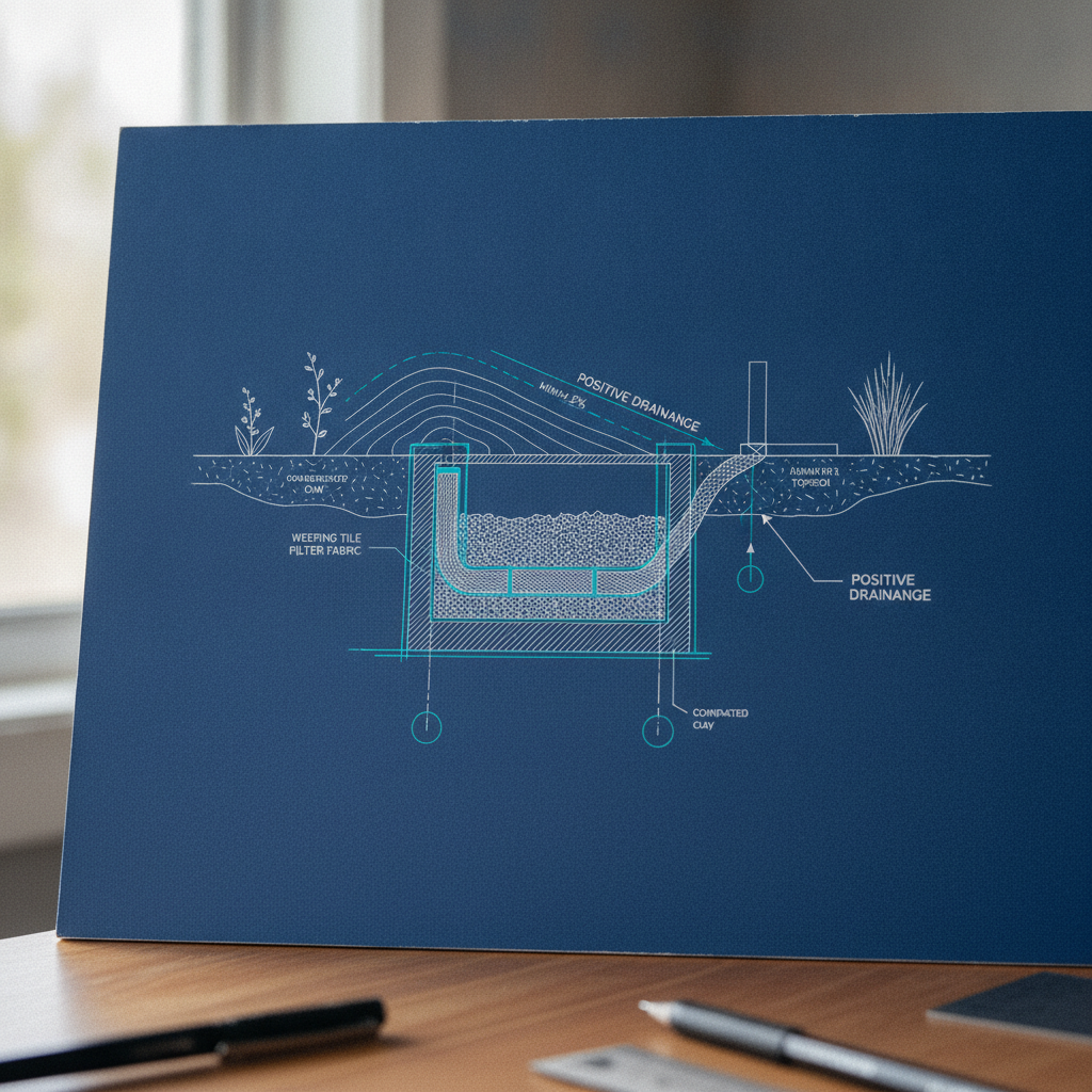
Every residential foundation in Alberta must be protected by careful grading and consistently positive drainage, as required by both the National Building Code - 2023 Alberta Edition (NBC(AE)) and municipal bylaws. Correct representation of these requirements on plan drawings, meticulous dimensioning, and detailed documentation of grading changes-both in the office and on-site-are crucial for passing permit review and preventing costly site problems. The process is intensely detailed, spanning code call-outs on site plans, the drafting of window well and stairwell drainage systems, precise depiction of downspout discharge, sectioning and dimensioning of grade transitions, and the workflow of revising and documenting these grades as real-world conditions unfold. The drafting desk is the frontline where design intent, municipal compliance, and onsite constructability converge-especially when it comes to grading foundations for Alberta’s demanding climate.
ABC Code-Compliant Grading on Site Plans: Depiction and Dimensioning
Minimum Slope and Drainage Direction-Code Reflected on Plans
Article 9.14.2.1. of NBC(AE) mandates unequivocally that the ground immediately adjacent to the building foundation must slope away to prevent water accumulation, with article 9.14.3.1. requiring a minimum slope of 10% for 2 meters-resulting in a 200 mm (7.87") drop away from any foundation wall. Most Alberta municipalities adopt this minimum as a baseline, with finer distinctions for hardscaped surfaces (1:50 or 2% slope standard) and nuanced rules for specific project types-such as Edmonton’s 0.75% slope for concrete or asphalt and 5% minimum for slab-on-grade commercial/multi-family work. These standards are enforced visually and dimensionally via site plan drafting, where both plan-view and spot elevation details must make code compliance plainly evident for each build and review.
Showing Existing and Proposed Spot Elevations
Site plans in Alberta are expected to distinguish between existing and proposed conditions. Drafting conventions call for dashed contour lines to represent existing grades; solid lines for proposed reshaping; and a typified system of spot elevations set at strategic locations-building corners, adjacent property boundaries, low points, and top-of-foundation datum. Spot grades are often box-annotated or encircled, usually outlined in a ‘GRADING INFORMATION’ table, and referred to in plan with keys such as:
- E:202.20 (Existing elevation at 202.20 m)
- P:201.98 (Proposed elevation at 201.98 m)
Clear annotation becomes vital when existing and proposed grades diverge significantly-as on infills or sloped sites-requiring each transition to be unambiguously called out to satisfy plan review tolerance. A foundational best practice is referencing all grades back to an established site datum-almost always taken as ‘Top of Foundation’ (TOF), typically marked as ‘TOF = 100.00’ for ease of calculation and clarity for all subsequent spot grades.
Graphic Conventions: Contours, Arrows, and Dimensioning for Slope
Slopes intended for drainage are rendered visually with grade arrows, each labeled with slope percentage (e.g., ‘2.0% SLOPE’ or ‘1:50’). These arrows must radiate away from the structure, reinforcing the 200 mm drop over first 2 m adjacent to foundation required by code. In areas of integrated landscaping or sitework changes, longitudinal profiles or enlarged sections may be added to further clarify positive drainage intent. A standard plan detail for a hardscaped pathway at grade may read:
- ‘Provide min. 2% slope away from building over first 2.0m. Slope to read 2.0% min. (1:50) overall-see gr. arrow for direction. Contours at 0.2m intervals.’
Where multiple grading features coincide-such as a swale bisecting a rear yard or a retaining wall at side yard setback-plans are expected to include a separate detail sheet with section cuts, base course elevations, and top-of-wall/grade-out annotations.
Standard Notes, Call-Outs, and Municipal Overlay
Standard compliance notes are not optional. Every grading plan should reference the controlling code section, such as:
- ‘All grading adjacent foundation to comply with NBC(AE) 9.14.3.1: 200 mm (7.87") drop over 2 m minimum, maintain positive drainage to all lot boundaries.’
Municipal overlays-such as the City of Edmonton’s ‘10% slope over 2 m, min. 200 mm drop’-must be confirmed and restated as required, with file references to permit checklists (e.g., ‘Refer City of Edmonton Lot Grading Minimum Grade Requirements’).
Real-World Plan Review Comments
Some of the most frequent redlines on Alberta site plans include:
- ‘Slope from foundation not clear-dimension explicit 2 m zone and call out 200 mm drop in both section and plan.’
- ‘Provide existing and proposed spot elevations at property corners and midpoints. Datum unclear.’
- ‘Ensure all grading arrows direct surface flows away from building-not towards window wells or walkouts’
Failure to represent positive drainage with these conventions results in resubmittals and project delays. Seasoned drafting teams preemptively add explicit notes such as, ‘Maintain all grades per code. Confirm finished ground slopes on site. Contractor responsible for final conformance.’
Material and Drainage System Specifications on Sheet
Engineered drainage solutions-such as perimeter weeping tile (4"/100mm PVC perforated pipe), mandatory filter fabric (non-woven geotextile min. 150 gsm), and granular backfill (washed gravel, 19 mm)-are referenced directly in detail call-outs. Each material is matched to location with tailored notes and section details, e.g.,
- ‘Backfill at foundation: Min 150 mm washed gravel, non-woven filter fabric throughout, connect to site perimeter tile at 2% min. slope to outfall.’
Detailed Drainage Solutions for Foundation Penetrations: Drafting Window Wells and Stairwells
Code-Mandated Solutions for Window Wells
NBC(AE) 2023, Section 9.14.6.3 requires every window well to ‘be drained to the footing level or other suitable location’ to avoid local flooding at the foundation. The required details for egress window wells are especially strict: the well must project min. 760 mm (30") outward in front of the window (as per egress escape rules), with 150 mm min. clearance past both edges of the opening, extending at least 300 mm (12") below the window sill to form a reliable gravel drainage zone. The well must rise min. 100 mm (4") above the finished adjacent grade (‘WELL EDGE MIN. 100 mm ABOVE FIN. GRADE’), preventing surface runoff intrusion.
Drawing Sheet Conventions for Window Well Drainage
Standard practice is to illustrate window wells in section for every unique foundation penetration, showing:
- Well depth (dimensioned vertical cut, e.g., ‘PROVIDE 300 mm GRAVEL BELOW WINDOW SILL’)
- Well width (clear min. 150 mm each side of window, total width = window plus 300 mm)
- Elevation of well top above grade and adjacent ground level slopes
- Drain pipe position (label: ‘100 mm PVC perf. drain tied to footing level weeping tile @ 1% min. slope’)
- Granular layer and filter fabric disposition
- Notes for window well materials (e.g., ‘GALV. STEEL PRECAST WELL’, ‘NON-WOVEN GEO-TEXTILE SEPARATION’, ‘WASHED DRAIN ROCK 19 mm’)
A typical call-out: ‘Drain window well w/ 100 mm (4”) perforated PVC, min. 1% slope to connect below frost line to perimeter drain; maintain filter fabric over granular. Base well edge >100 mm above grade. See detail S1/A-301.’
Detailing Exterior Stairwell Drainage
While the code is less explicit about stairwells, Section 9.14.6.1 mandates that drainage ‘shall prevent water accumulation at or near the structure.’ Detailing stairwells involves depicting section profiles with a dedicated catch basin or trench drain at the base, grating to exclude debris, and connection lines to the main perimeter drain or a drywell system. Minimum drain size is specified in notes: ‘Provide 100 mm (4”) perforated PVC leader, 1% min. slope, to perimeter weeping tile.’
- Section call-out: ‘EXTERIOR STAIRWELL DRAIN-100 mm PVC PERF. W/ BACKWATER VALVE, MIN 1% SLOPE TO FOUNDATION TILE; COVER DRAIN WITH GRATED STRAINER. BASE OF WELL MIN 300 mm BELOW LOWEST STEP.’
Key clearances: stairwell-to-property line (often 1.2 m), riser heights per NBC, and graded sideslopes away from foundation wall at the base of the stairwell.
Critical Redlines and Field Review
Repeated plan review comments target:
- ‘Provide connection detail of window well drain to footing level tile-clarify with section.’
- ‘Bedding and filter fabric not shown-add call-outs to detail.’
- ‘Drainage for stairwell absent-add drain with min pipe size/slope and indicate route to tie-in at main perimeter drainage.’
Sloppy or minimalist plan details, such as showing drain lines as leader arrows with no section, are returned for correction. Standard of care in Alberta is fully detailed well and stairwell assemblies, with all critical dimensions, typical notes, and explicit drainage connectivity.
Managing Roof Water Discharge: Detailing Downspouts and Stormwater Routing on Drawings
Downspout Placement and Symbol Conventions
Downspouts (leaders) are depicted on site and roof plans with standardized symbols-most often a filled circle or square with leader lines and arrowheads indicating flow. Each downspout position must correspond with the roof plan’s watershed breakdown, ensuring all water is collected and routed appropriately. Placement should avoid roof valleys over penetrations or entryways, and be coordinated with ground-level grading to maintain positive surface drainage.
- Symbol call-out: ‘DS’ w/ arrowed leader; Schedule references: ‘DOWN-SPOUT LOCATIONS TO COORDINATE WITH GRADING PLAN.’
Minimum Discharge Distances and Treatment
Municipal requirements dictate hard minimums for water ejection away from the foundation. For example, the City of Calgary enforces:
- Downspout extensions/splash pads must end min. 2 meters (6.6 feet) from any sidewalk, alley, or road (Calgary Stormwater Bylaw)
- Edmonton requires all downspouts discharge a min. 1 meter (3.3 feet) away from the foundation, with clear direction of flow towards drainage swales and within property lines
Typical plan notes detail these limits:
- ‘ALL DOWNSPOUTS TO EXTEND MIN. 1M FROM FOUNDATION. PROVIDE SPLASH PAD OR FLEXIBLE EXTENSION-DO NOT DISCHARGE WATER ONTO ADJACENT LOTS.’
If a tie-in to a site storm sewer is provided, include a typical connection detail-e.g., ‘DOWN-SPOUT TO 100 mm PVC STORM CONNECTION @ 2% SLOPE; SEE DETAIL S2/C-401.’ In the absence of a site system, plans require detail call-outs for splash pads (‘PREMANUFACTURED CONCRETE PAD 450 x 900 mm, SLOPED TO GRADE’), rigid elbows, or extended flexible leaders-labeled as ‘TO BE PLACED AT FINAL GRADE, LENGTH AS REQ’D FOR 1M CLEARANCE’.
Coordination with Roof Plan and Surface Grading
Roof and site plans must be coordinated for review, with all downspout locations and discharge points marked, cross-referenced, and dimensioned in plan view. Each should show:
- Location at building face (plan), vertical alignment to eave (elevation), and corresponding roof drainage zone (roof plan)
- Discharge location and distance from foundation or hard surfaces
- Swale entry coordinations or ‘DAYLIGHT TO GRADE’ notations where appropriate
Any hardscaped areas in the ejection path require added detail-e.g., concrete pads sloped min. 2% away from the building, control joint call-outs at foundations, and erosion control measures such as splash block notes (‘PROVIDE SPLASH PAD AT DOWNSPOUT, SLOPED TO DRAIN-SEE GRADING PLAN FOR FLOW DIRECTION’).
Common Plan Review Redlines
Recurring comments during municipal review focus on:
- ‘Downspout discharge ends too close to foundation-revise to show min. 1m (or 2m as local bylaw) from wall’
- ‘Show how downspout flows integrate into overall lot grading-ensure water doesn’t flow onto adjacent properties’
- ‘Coordinate roof and site plans-relocate downspout outfalls clashing with walks, patios, or driveways’
Plans without explicit stormwater routing are flagged for revision and require additional section/detail sheets before approval.
Drafting Complex Grade Transitions: Hardscape, Softscape, and Swale Integration Details
Intersecting Hardscape and Softscape: Expansion and Control Joints
Hardscape-softscape intersections present frequent drainage risks. Where driveways, walkways, or patios abut the building, expansion joints must be detailed clearly-drawing upon Alberta Transportation Specification 4.2, which stipulates ‘full depth preformed expansion joint filler at all junctions with structure’. Joint call-outs commonly state, ‘PROVIDE 13mm FIBREBOARD EXPANSION JOINT (ASTM D1751) AT CONTACT POINT; SEAL W/ BACKER ROD AND POLYURETHANE CAULK.’
Control joints are drafted at 3-4 meter intervals in slab sections, typically dimensioned (‘CONTRACTOR TO SAWCUT CONTROL JOINTS AT 3m o.c., ALIGN W/ COLUMN GRIDLINES’), and referenced on the general notes page.
Different Slope Requirements and Transition Detailing
Satisfying code’s demand for positive drainage means correctly dimensioning different landscape elements:
- Hard surfaces (concrete/asphalt): 2% slope minimum per NBC(AE) and City of Edmonton overlays; dimensioned in plan/section as ‘MIN 25 mm DROP PER 1.2m CONC. SLAB’
- Soft landscape: 5% slope (1:20) adjacent the building, dimensioned as ‘60 mm DROP PER 1.2m TURF TO EDGE OF BUILDING’
- Combined or variable surfaces (e.g., patio terminating at softscape): slopes reconciled in spot elevation notes and through transition details illustrating gradual blending
Where these surfaces meet, clear breaklines and transition annotations such as ‘HARD/SOFT INTERFACE: BEGIN 2% SLOPE AT EDGE OF CONCRETE, MATCH 5% SLOPE FOR FIRST 2.0m OF TURF’ are critical for both builders and reviewers. Omitted or ambiguous transitions are leading causes of redlined revisions.
Swale Representation: Graphical and Dimensional Standards
Swales are drafted as shallow, typically grassed channels, shown both in plan (‘DASHED LINES; LABEL: “PROPOSED GRASS SWALE-1m WIDE, 200mm DEEP, 1.5% SLOPE TO REAR YARD”) and in dedicated sections. City of Edmonton standard is:
- Min. 1 m bottom width (for grass swale), 150-200 mm depth, with side slopes 3:1 or gentler
- Grade slopes typically 1.5%-2% for turf, 1% for paved/concrete swales
Plan notes might specify, ‘ALIGN SWALE FLOW WITH LOT BOUNDARY; MAINTAIN MIN. 1.5% SLOPE, VERIFY FIELD GRADES.’ At intersections with driveways and hard surfaces, show flush transitions or pipe underdrain where required.
Common Grade Transition Issues and Redlines
Among the most frequent corrections:
- ‘Patio/driveway grades show reverse (negative) slope-recalculate to ensure positive drainage away from building, confirm with spot elevations.’
- ‘Swale section missing-add spot grade points and depth call-outs in both plan and section.’
- ‘Expansion joint missing at hardscape/foundation-add detail as per specification 4.2, mark on plan.’
Unclear or un-dimensioned transitions lead to risk of ponding, foundation damage, or municipal failure at pre-backfill inspection; as such, sectioned details with dimensioned depth, slope, and material specifications for every swale or junction are required.
Material Specs for Grade Transition Details
On Alberta plan sheets, concrete called out for driveways and patios is typically 32 MPa compressive strength, air-entrained for freeze/thaw durability. Joint filler at building interfaces must meet ASTM D1751. Details for swales may specify sod/root mat, riprap (selected stone 75-150 mm), or reinforced turf (when subject to frequent channelized flows), with all surface finishes noted as ‘NON-SLIP FINISH’ for pedestrian safety.
Responding to Plan Review Redlines and Documenting Jobsite Grade Adjustments
Typical Redline Comments and Sheet Revisions
Permitting authorities in Alberta are rigorous in their grading review. Redline comments are direct-examples include:
- ‘Clarify positive drainage away from entire foundation perimeter. Add directional arrows and spot elevations at all transitions.’
- ‘Show both existing and proposed grades at all lot corners and midway along property lines.’
- ‘Provide full detail on window well drainage-depth, drain location, tie-in to perimeter tile.’
Each comment must be addressed with revised drawings, changes clouded for reviewer visibility, and updated drawing indexes (‘REV B: ALL GRADES AND ARROWS REVISED AS PER CITY COMMENTS, 2024-02-28.’).
Drafter’s Role: Issuing Revised Drawings and Clarifications
Once comments are received, the drafter must:
- Compile all redline comments into a ‘REVISION RESPONSE MATRIX’, explicitly mapping each reviewer comment to a drawing update or code reference
- Revise grading sheets, site plans, and details, inserting/adjusting spot elevations, grade arrows, call-outs, or drainage system routing as directed
- Cloud all modifications (revision clouds in drawing file), update revision history block (‘REV C: ADDED STAIRWELL DRAINAGE SECTION AND SPOT GRADE CALL-OUTS’)
- Issue revised sheets as part of an Architectural Supplemental Instruction (ASI) or respond directly to a Request for Information (RFI), as procedure requires
Clear, detailed change explanations in transmittal emails or revision notes (“Per reviewer’s mark-up: All plan slopes along west property boundary adjusted to 2% min. with revised spot elevations at 10 m intervals; window wells now detailed as per 9.14.6.3 with footing tie-in sections S3/A-206.”) expedite approvals.
Jobsite Reality: As-Built Documentation and Field Sketches
Actual finished grades on site may deviate from plans due to unforeseen field conditions-hard digging at utility crossings, rock, or deviations from imported fill. Drafters are tasked with:
- Recording final grade elevations in ‘AS-BUILT’ plans, with all deviations from original spot grades tabulated and noted for authority sign-off
- Compiling and referencing field sketches-drawn at scale or by marked-up photos-showing real slab/grade levels, new drain or swale routing, and utility conflict adjustments
- Filing a narrative of why grades were altered (‘ROCK AT 4.8M DPT-GRADE RAISED 120 mm FOR COVER’ or ‘SAN SEWER ENCOUNTERED AT 2.7M OFFSET-SWALE SHIFTED 1.2M WEST AND GRADE FLATTENED TO 1% AT LOW POINT’)
- Communicating changes to all parties: site super, subtrades, city inspector, and, as needed, design professionals for sign-off
These as-built grading sheets form the record for final inspections. In Alberta, final occupancy is contingent on compliance with both code-stipulated minimums (‘200 mm drop in 2.0 m adjacent foundation’) and local bylaws for lot drainage and swale continuity.
Procedures for Recording and Communicating Grade Changes
A disciplined protocol ensures no grade changes go undocumented:
- Site instructions (often ‘Field Order’ or ‘Site Memo’) issued by the designer or site superintendent, sketched and dimensioned as necessary
- Revised digital grading sheets (‘AS-BUILT GRADING PLAN-JULY 2024’) are prepared showing actual final grades using surveyed data, including all adjusted spot elevations
- Change summary delivered with contractor’s certification for new grades, distributed to city inspector and attached to permit file for sign-off
- Updated site plan and elevation sheets highlight any last-minute changes in bold or clouds to ensure all stakeholders are working with current information
Specific Dimensions and Material References in As-Built Docs
As-built sheets must reaffirm all critical code minimums:
- Grade at foundation: ‘MIN. 200 mm DROP OVER 2.0 M’
- Window well elevations: ‘113.40m T/WELL, 113.05m B/WELL, CONNECTS VIA 100 mm PVC DRN’
- Downspout extensions: ‘END @ 1.2m FROM FNDN EDGE-DIR TO SWALE’
Conclusion
Delivering truly functional, code-compliant finished grade and drainage for Alberta residential foundations is a drawing-intensive, dimensionally rigorous process-demanding precise site plan representation, well-detailed sections for all foundation penetrations, clear coordination of roof discharge, fine-tuned integration of hard/softscape and swales, and a robust workflow for plan review revisions and real-world as-built grading docs. Each plan sheet, call-out, and field update is instrumental in achieving a resilient foundation for Alberta homes and communities.
For accurate, compliant, and builder-focused residential architectural drafting in Alberta, count on Kingsway Drafting & Design.