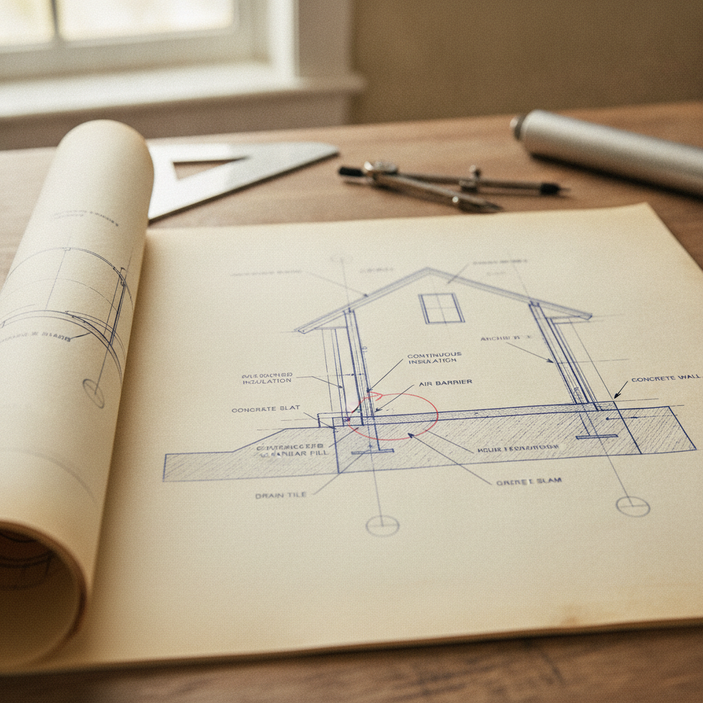
The junction between an attached garage slab and a house foundation represents one of residential construction’s most critical detailing challenges in Alberta’s unique environment. The region’s wide-ranging climate, soil variability-especially the prevalence of expansive clays-and stringent code requirements converge at this critical interface. Overlooking even a single requirement or detail can yield costly consequences: differential settlement, moisture penetration, persistent thermal losses, or even compromised fire separation. Skillfully navigating the National Building Code - 2023 Alberta Edition (NBC(AE)) with real-world constructability in mind is essential for successful, compliant builds that stand the test of time.
Foundation Requirements: Navigating Code and Soil Realities
Foundation Depth and Platform Consistency
One of Alberta’s defining geological challenges is the occurrence of highly plastic clay soils, whose volume fluctuates significantly in response to moisture changes. Infill projects in older neighborhoods frequently encounter such substrates, while new developments on previously agricultural land may face radically different bearing conditions just meters apart. The code mandates that attached garage footings must typically match the depth of the house’s footings wherever expansive or variable soils pose a risk, and this requirement is far from arbitrary.
In practice, when a garage slab is set on a shallow-grade beam or thickened edge, and the house foundation is on full-height basement walls stretching well below frost level, the result is often pronounced differential movement. Over time, seasonal moisture changes cause the garage slab to heave or settle at a different rate than the more deeply anchored house footings. As any experienced architectural drafter or site supervisor attests, the visible manifestation is a cracked, displaced slab at the junction, with doors and finishes suffering alignment issues. Matching foundation depths, while sometimes increasing excavation or forming costs, represents a prudent investment in future durability and drastically reduces costly call-backs.
Key steps during the drafting phase include:
- Deliberate alignment of footing elevations between house and garage where soil analysis suggests clay, silt, or variable fill.
- Incorporation of stepped footings or frost-wall junctions where grade or house form necessitates elevation changes.
- Explicitly referencing geotechnical recommendations in the drawing set and including cross-sections that clarify the intended relationship between garage and house foundation elements.
Construction Joints: Engineering for Movement, Not Against It
The NBC(AE) requires a positive construction joint between house and garage slabs, recognizing that-regardless of efforts to unify footings-differential movement is always a possibility. A common-but ultimately flawed-approach in the field is to simply pour both slabs monolithically or to rigidly dowel them together. This shortcut, while expedient short-term, all but guarantees future cracking as the two building masses respond independently to environmental and occupancy loads.
Well-documented best practice is to draft an intentional joint, often with a compressible expansion strip (such as asphalt-impregnated fibreboard) set vertically between the house foundation wall and the garage slab edge. This joint, typically specified at 12-20 mm (1/2”-3/4”), allows for slight movement, preventing stress transfer into the house slab or footings. Drafters detail the joint’s geometry, specify the compressible material, and-critically-call for a high-performance, UV-resistant sealant bead along the slab surface to ensure water tightness. Where the garage slab is set lower than the house, the joint should extend vertically to meet the wall air/vapour barrier plane, maintaining continuity for air and moisture control. Annotating these requirements clearly on both plan and section sheets, while referencing appropriate manufacturer specifications, makes enforcement and inspection in the field straightforward.
Frost Protection: A Freeze-Thaw Reality
Alberta’s winter lows and unpredictable freeze-thaw cycles make frost heave prevention a non-negotiable design priority. Unheated or only partially heated garages are at particular risk: when footings or perimeter slab edges are set above design frost depth (typically at least 1.2 m below grade in most zones), freezing soils can lift or tilt the slab. This is exacerbated in north- or east-facing garages or those shielded from winter sun where the ground remains frozen deep into spring.
Drafters address frost protection on plans by:
- Clearly dimensioning all foundation and grade beam depths on both plans and sections, making specific note of any step-downs at the garage/house interface.
- Detailing insulation strategies where slab edges are close to grade-a continuous R10 (RSI 1.76) rigid insulation horizontal skirt is sometimes called for, extending 1 m out from the slab edge, to reduce frost penetration for shallow footings.
- Referencing local frost depth tables and-where soil or microclimate conditions merit-calling for augmented depths or insulation systems per NBC(AE) and municipal guidelines.
- Labeling unheated and heated conditioned spaces prominently, clarifying how foundation requirements change accordingly.
Providing unambiguous dimensions and sequence notes ensures contractors and inspectors interpret the frost protection strategy exactly as intended, reducing the “grey zone” disputes that often persist with site-built garages.
Garage Floor Sloping and Drainage: Draining Away Trouble
Specifying the Slope: Numbers That Matter
Garage floors double as catch-basins for snowmelt, rainwater, vehicle drips, and every conceivable household chemical. The code demands positive drainage towards the exterior, typically interpreted as a minimum slope of 2% (1:50)-a 25 mm (1”) drop over a 1.2 m (4’) run.
The drafter’s responsibility is to annotate both plan and section views unambiguously-calling out the highest finished floor elevation at the inside face of the house-garage demising wall and the lowest at the garage door sill or apron. Including a spot elevation grid is a best practice, supporting both contractor layout and inspector verification. In garages wider than a single bay, drafters may break up the slab into multiple drain zones or direct slope not just to a door but to a trench drain if large vehicles or in-slab utilities require. Clearly detailing isolation at interior columns or control joints at slope transitions minimizes risk of unintentional water pooling-an early indicator of drafting ambiguity or field misinterpretation.
From a practicality standpoint, over-specifying slope (e.g., 4% or more) can create ergonomics and vehicle ingress issues. Drafters must balance risk tolerance (greater slope for heavy snow loads and quick melting) against usability, referencing manufacturer warranties for floor coatings and ensuring compliance with barrier-free design where required.
Fire Separation: Drawing the Line Between Safety and Occupancy
Understanding Fire-Resistance Ratings in the Alberta Context
Alberta’s residential building landscape ranges from massive multi-garage custom homes to slim-lot infills, but the NBC(AE) mandates a strict minimum: a 1-hour fire-resistance rating between attached garages and adjacent living spaces. This is not merely bureaucratic-ignition sources such as vehicle fuel, cleaners, and even battery storage drastically increase fire risk in garages, demanding real performance from separation assemblies.
Effective drafting delivers this by calling for:
- Wall Assemblies: Minimum 12.7 mm (1/2") Type X gypsum board-on the garage side of all demising walls. In some situations, dual layers or additional mineral wool are specified for higher performance or to address penetrations (e.g., ducts, pipes).
- Ceilinings and Overhead Conditions: For bedrooms built over garages, two layers of 12.7 mm Type X gypsum or a combination of gypsum and resilient channel may be needed, with clear details for all mechanical, plumbing, and electrical penetrations.
- Continuous Detailing: Including enlarged details at the wall-floor and wall-roof transitions, showing how fire-rated assemblies connect and maintain their rating across construction joints, slab edges, and utility chases.
A key pitfall often seen in residential projects is unclear direction on continuing fire-separation treatment across slab edges and construction joints. Drafters must specify firestopping systems-ULC-listed for 60 minutes or more-at locations where the garage slab abuts the house foundation or where services cross the separation. Calling out manufacturer and UL design numbers in drawing notes assists both the trades and permitting officials in verifying code compliance during inspections. For projects where garage-to-house transitions are complex (angled walls, stepped footings), including isometric or perspective views within the drawing set can aid understanding and enforcement.
Interior Finishes and Penetrations
Even with fire-rated walls and ceilings, penetrations remain a chief vulnerability: electrical conduits, plumbing stacks, HVAC ducts, and even minor outlets can undermine an entire assembly’s rating if not correctly detailed. The NBC(AE) insists that any penetration be tightly sealed with listed firestop products, restoring required performance. Drafters minimize risk by:
- Clustering electrical and mechanical runs in specific wall locations, allowing for grouped penetrations (which are easier to observe, measure, and treat).
- Showing enlarged detail callouts at all planned penetrations, specifying assembly numbers and proprietary solutions for firestop caulks, wraps, or boots.
- Labelling the required sealant depth, backer rod diameter, and any necessary retaining clips for overhead pipes or conduits.
For ambitious home or multifamily projects, this may extend to coordinating with subconsultants (mechanical, electrical) during the drafting phase-integrating their plans into the architectural set and incorporating “No Penetration Zones” in especially sensitive areas. This collaborative, coordinated approach pays dividends in reducing costly field modifications.
Structural Considerations: Engineering for Alberta’s Realities
Differential Settlement: Anticipating Ground Truths
Differential settlement between house and garage represents a persistent risk, particularly when foundation types or depths differ. While matching foundation depths mitigates much of this, additional steps help draft for resilience:
- Explicit Construction Joint Design: Instead of rigidly connecting the garage slab and the house foundation wall, use dowels with flexible sleeves or complete downgrade of all mechanical tie-ins to prevent unintended load transfer.
- Subgrade Compaction and Preparation: Section details should call up compaction requirements for garage slab subgrade-typically to at least 98% of Modified Proctor density-to minimize future movement. Inclusion of granular base thickness, drainage layer details, and geotextiles enhances performance, especially over fill soils or conversions (e.g., parking slab over former lawn).
- Monitoring and Documentation: Adding notes that require the contractor to submit pre-pour photographs of compaction and sub-base preparation provides an inspection-ready trail, supporting both warranty protection and municipal sign-off.
- Step Details for Split Grades: Alberta’s hilly terrain often mandates split-level garages or “sunken” mudrooms. Drafters detail step-downs in both slab and foundation walls, clearly coordinating with structural engineering and specifying reinforcement overlap/splicing at stepped transitions to avoid stress concentrations and cracking.
By visually reinforcing these requirements across plans, sections, and details, the drawing set becomes a contract for performance, guiding not just compliance but true longevity of the connection.
Soil Assessment: The Hidden Variable
The geotechnical survey is a drafter’s insurance policy. In new subdivisions, developers may provide soil reports, but renovators or custom builders working on infill lots must commission their own borehole tests. The drafter’s plans should:
- Reference the soil report directly-citing bearing capacity assumptions, groundwater tables, and any recommendations for sub-slab drainage or specialty footings (e.g., piles, pad footings).
- Include contingency details: for instance, specifying slab thickening or grade beam reinforcement if soils are identified as particularly weak or expansive.
- Detail waterproofing or drainage measures that respond to specific site recommendations-such as extra drainage tile or sump pit placement if high water tables are identified.
Annotating the geotechnical context elevates the drawings from generic “one size fits all” to truly site-specific solutions-critical for permit approval in Alberta’s tightly regulated urban jurisdictions.
Moisture Control: The Battle Against Water
Waterproofing Details at the Junction
Moisture ingress at the house-garage slab interface frequently emerges as the failure point in otherwise high-end residential projects. Even small leaks can cause long-term mold growth, ruin finishes, or damage stored goods. To avoid this, drafter’s details must include:
- Vertical Damp-Proofing: The interface between the garage slab and foundation wall is a high-risk path for capillary moisture movement. A peel-and-stick membrane, lapped up the face of the wall and beneath the slab, effectively breaks this path. The drafter should specify the membrane type (e.g., self-adhered rubberized asphalt), indicate lap widths (typically 100 mm / 4”), and show termination details above grade for inspection.
- Horizontal Capillary Breaks: Including a granular drainage layer (minimum 150 mm / 6” clear granular fill) beneath the garage slab not only assists in drainage but breaks capillary rise from damp soils. Drafters should cross-hatch or annotate this base clearly, referencing compaction and material standards.
- Curb Details: Raising the finished garage floor at least 100 mm (4") above surrounding exterior grade, with cross slopes away from the house, further mitigates surface water intrusion. The drafter’s sections must emphasize these dimensions and include flashing notes at all door sills.
Drainage Systems: Out of Sight, Not Out of Mind
Weeping tile-perforated pipe set below footing level and drained to a sump or storm system-is increasingly specified even for garage perimeters. On plans, drafters should:
- Show all perimeter drainage tile runs, connection details at foundation steps, and outlet or sump locations.
- Reference filter fabric wraps and cleanouts, especially where silty soils or construction debris are common.
- Include notes for connections to municipal storm systems or to approved drywells where required by city code.
Such proactive documentation heads off future drainage problems that are both expensive and disruptive to remedy after the fact.
Thermal Bridging: Sealing Energy and Comfort
Continuous Insulation Strategies
Garages are often unheated or only marginally conditioned, making the common wall and floor junctions notorious for energy loss. The NBC(AE) requires the thermal envelope (including slab edges) to be continuous without thermal shortcuts. The drafter’s role is clear:
- Slab Edge Insulation: For slabs adjacent to heated basements or main floors, detailing a continuous rigid insulation board along the slab edge-at least 50 mm (2”) thick, R10+-interrupts thermal conduction through concrete. Sections should show the insulation running from below grade up to the bottom of the sole plate, with clear callouts for material type and fastening method.
- Interface Detailing: For step transitions or odd angles, isometric or 3D details clarify how to “wrap” insulation seamlessly up wall returns or under sills, preventing even small cold spots that lead to condensation and mold. Drawing notes should coordinate the insulation with air barrier location and flashing where exposed to the weather.
- Upgraded Wall Systems: Where garages share a wall with living space, specifying a higher-performance stud wall (e.g., 2x6 at 24” o.c. with R22 batts plus R5 continuous exterior insulation) reduces heat loss, improves resilience during severe cold snaps, and may improve energy ratings for permitting or rebate programs.
Implementing Thermal Breaks
To further reduce the impact of thermal bridging at the slab/foundation interface:
- Incorporate pre-manufactured thermal breaks (e.g., foamglass or structural plastic components) beneath slab edges abutting the house, as called for in engineered slab designs.
- Extend vapor-permeable insulation across control joints where the garage slab “floats” away from the main structure, using compatible expanders and flexible adhesives to maintain continuity.
- Coordinate with mechanical designers to avoid routing ductwork or major pipes through these cold zones-or call out supplementary insulation and protection where no alternative exists.
Enhanced thermal detailing not only meets code, but also diminishes long-term heating costs and supports occupant comfort in both garage and adjoining living spaces.
Construction Joints: Specifying Flexibility and Protection
Strategic Joint Placement for Crack Control
Uncontrolled cracking is a top complaint for attached garages, usually traced to either poor joint layout or incorrect treatment at the junction with the house foundation. Drafters solve this by:
- Overlaying a control joint plan on the garage slab that aligns joints perpendicular to the house wall or foundation, typically at 3-4 m (10-13 ft) spacing for unreinforced slabs, and at all re-entrant corners or transitions.
- Labeling both saw-cut and tooled joints on the documents, with section callouts showing depth (typically at least 1/3 slab thickness for effective crack control).
- Detailing construction joints at all slab/foundation interfaces-always with a compressible filler and indicated sealant as previously described.
Best Practices in Sealants and Joint Fillers
Using the right joint filler and sealant is critical, especially given Alberta’s high-UV, freeze-thaw environment:
- Specify backer rods and elastomeric sealants (e.g., urethane-based or silicone) capable of surviving repeated movement and temperature swings without becoming brittle or peeling.
- Reference manufacturer application instructions: temperature range, primer requirements, and recommended cure times.
- On key details, show cut-away diagrams so the installer cannot mistake the layering order-foundation, compressible filler, sealant, and slab edge.
Material Selection: Durability and Performance
Concrete Mix, Strength, and Finishes
The garage is an inherently hard-working space-subject to vehicular point loads, freeze-thaw cycling, de-icing salts, and traffic abrasion. The drafter’s specification can make the difference between a slab that endures and one that fails prematurely:
- Reference a 32 MPa (4640 psi) concrete mix with at least 5-8% air entrainment for slabs exposed to freeze-thaw, which improves long-term durability.
- Annotate the use of low-permeability concrete or supplementary cementitious material (SCM) blends (e.g., fly ash, slag) for enhanced moisture and salt resistance.
- Include finish direction (e.g., light broom finish perpendicular to slope) and curing requirements-7 days minimum moist cure or membrane curing to reduce surface crazing.
Reinforcement Practices
Although the NBC(AE) allows unreinforced garage slabs in some settings, real-world experience shows that proper wire mesh (e.g., 150 x 150 mm 6/6 WWM) or #10 (10M) rebar grids substantially enhance resistance to cracking, especially near construction joints. The drafter should:
- Call out reinforcement pattern, clear cover (minimum 50 mm / 2” for exterior exposures), and lap lengths at all corners and joints.
- Detail doweling at slab/foundation interfaces where required, but always sleeved or de-bonded to avoid restricting differential movement.
- Where slab heating (hydronic, electric) is included, overlay those system lines on the reinforcement details and include conflict notes.
Air Sealing: Protecting Indoor Air Quality
Air Barriers and Fume Control
Garages are a major entry path for vehicle exhaust, gasoline fumes, and other hazardous substances. A tight air barrier is crucial at the house/garage junction:
- Detail the continuity of the air barrier from the below-grade wall (exterior peel-and-stick membrane or parging) to the above-grade house wrap/moisture barrier, making sure any joint at the slab/foundation is overlapped and sealed.
- Use approved sealants and tapes, and demonstrate on detail sheets how barriers transition across varying wall thicknesses, step-downs, or beam pockets.
- In multi-level homes, pay particular attention to rim joist zones above garages, where air barrier continuity is easily compromised-detailing rigid insulation and spray foam infill as appropriate.
Sealing Penetrations Rigorously
Penetrations are inevitable, but with clear documentation, risk is controllable:
- On both plan and section, identify all intended penetrations early and call out the required air sealant type (acrylic, polyurethane, or advanced tape), as well as required wrap or boot type for pipes and conduits.
- Coordinate penetration locations to minimize their number and avoid placing them in hard-to-seal transitions.
- For larger penetrations (e.g., duct boots), detail fire-, air-, and vapor-resistive wrap systems, referencing ULC-approved assemblies and installation sequencing.
At inspection, well-documented and easily understood air-barrier detailing is often the difference between first-pass approval and costly rework.
Best Practices and Common Pitfalls
- Documentation Discrepancies: Inconsistencies between plan, section, and detail sheets lead to site confusion and misbuilds. Coordinating all elevations, foundation depths, and insulation details on every relevant page avoids this risk.
- “Shortcuts” in Fire or Air Separations: Relying solely on finish trades or after-the-fact patching to maintain fire- or air-barrier integrity is insufficient. Drafter must demand in-sequence, purpose-built solutions that remain inspectable at every stage.
- Delegate to Specialists Where Needed: Some site conditions (e.g., high groundwater, steeply sloped lots, nonuniform fill) require structural engineers or specialist waterproofing consultants to formalize details. Even then, the drafter’s role is to coordinate, clarify, and visually assist their recommendations.
- Permit Reviews and Field Verification: Proactively addressing typical municipal red-flag concerns (frost protection, drainage, fire rating continuity) on the drawing set accelerates permit approvals and reduces back-and-forth with officials.
Conclusion
Success at the garage slab/house foundation junction depends on more than just code literacy; it’s the convergence of thorough documentation, real-world constructability, and clear communication with field crews and inspectors. The drafter’s role is to anticipate site challenges, translate code into sequenced, constructible detail, and document every assumption-elevating quality, safety, and performance across Alberta’s diverse building landscape. For the most up-to-date, site-specific solutions, always confirm NBC(AE) requirements with your local authority and supplement with geotechnical evaluations and manufacturer best practices in your drafting set.
Kingsway Drafting & Design provides Calgary area homeowners, builders, and developers with expert, code-compliant drafting for every stage of residential construction, ensuring every garage-to-house junction meets Alberta’s highest standards.