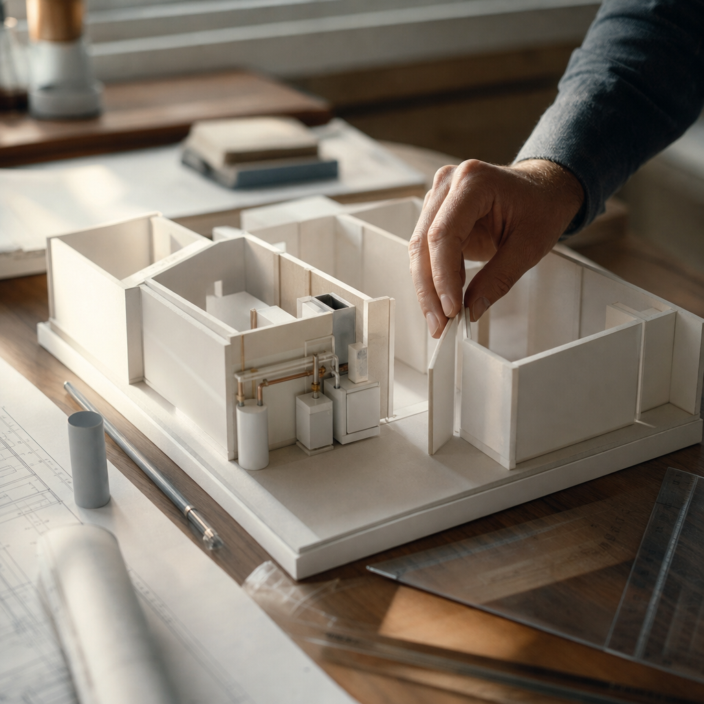
Precise mechanical room layout for residential furnaces and water heaters in Alberta is governed by rigorous code clearances and drafting standards. Modern drafting practice integrates Alberta Building Code (ABC) 9.32.4.2, adopted CSA B149.1/2, and key plan conventions to head off common plan-review redlines, eliminate jobsite RFIs, and ensure safe, serviceable installations.
Integrating ABC 9.32.4.2 and CSA B149.1/2: Dimensioning Furnace and Water Heater Clearances and Access
Working space for mechanical units is a cornerstone of code-compliant residential design in Alberta. Section 9.32.4.2 of the Alberta Building Code stipulates the provision of adequate space for safe operation and maintenance of fuel-burning appliances. Floor plans and mechanical room layouts must reconcile these code expectations with the more granular clearance tables of CSA B149.1-2025 (Natural Gas and Propane Installation Code) and CSA B149.2 (Propane Storage and Handling Code), both adopted for enforceability in Alberta as of the 2026 code updates.
Dimensioning Methodologies on Floor Plans
- Code Citation: ABC 9.32.4.2 states: "Sufficient working space shall be provided for operation, maintenance and inspection of the appliance." Although the ABC does not assign numeric values, it defers to CSA B149.1-2025 and manufacturer installation manuals for minimums.
- CSA B149.1 Clause 4.5.4: "Clearance from combustible construction shall be at least as great as shown on the appliance nameplate [or] installation instructions."
For most residential furnaces and standard tank water heaters:
- Service Access: In the absence of manufacturer's instructions, maintain a 30-inch (762 mm) minimum clear zone at the control side as a default per accepted practice and trade norms.
- Combustion Air: Integrate a 30-inch (762 mm) working space in front of air intakes and control panels.
- Adjacent Structure Clearances: Annotate minimum lateral clearances (often 1-2 inches or as specified) for flue and vent clearances in accordance with manufacturer and code.
Dimension lines are to be pulled from finished wall faces to the edge of appliance casing, with a dashed rectangle denoting required code clearances. These working spaces are distinct from (and supplemental to) any appliance-specific installation clearances noted on product data sheets. Always verify manufacturer’s minimums as more restrictive requirements override the default values.
Drafting Standard Notations and Access Zone Conventions
- Hatch Patterns: Service/clearance zones are hatched with a light diagonal pattern, labeled "Service clearance, maintain min. 30" (762 mm) clear, per CSA B149.1-2025."
- Annotations: "Provide clear, unobstructed access to appliance controls and service panels. See Detail A for clearance requirements."
- Detail Call-Outs: “Detail A: Furnace/water heater working space and access clearances per manufacturer and CSA B149.1-2025.”
Elevations and building sections illustrate vertical clearance above the unit and to any overhead obstructions, especially important for direct-vent appliances, power-vent terminations, and expansion tank installations (reviewed further below).
Typical Plan Review Redlines for Insufficient Clearances
- "Inadequate clearance in front of furnace, revise to provide min. 30" (762 mm) per CSA B149.1-2025."
- "Obstructed access to water heater controls. Relocate partition, provide clear working space for maintenance/service."
- "Provide hatch or dashed outline for code minimum service area at mechanical equipment."
- "Specify non-combustible material for enclosure/clearance as per code."
Failure to dimension these zones, omit hatch patterns, or leave clearances ambiguous nearly always results in resubmittals and jobsite clarifications. These comments can be avoided by explicit referencing of clearance details in the drawing set, using code sections and manufacturer specs directly in notation.
Material and Section Conventions
- Draw enclosures and cabinetry in section or elevation to show clearances to combustibles (per B149.1/2).
- Mark protective barriers and their materials, indicating fire rating as required if the appliance is in proximity to storage or egress spaces.
- Reference manufacturer data sheets and note on mechanical plans: "All clearances per latest manufacturer’s installation manual or as required by CSA B149.1/B149.2, whichever is greater."
Direct cross-referencing code and product data on the plan cuts out ambiguity, reducing repetitive RFI cycles from trades and inspectors during build-out.
Combustion Air and Combustion Air Supply Notation
- “Maintain min. area and open path for combustion air per CSA B149.1-2025 Clause 8.4. Size and route ducting/grille openings as detailed.”
- "Combustion air grille: min. XX in² net free area, non-obstructed. Refer to mechanical schedule and Detail B."
Drafting Code-Compliant Combustion Air Openings and Venting Clearances (ABC 9.32.3.2, CSA B149.1/2)
Detailed representation of combustion air paths and venting is central to Alberta permit review and field inspection. ABC 9.32.3.2 combines with CSA B149.1/2 to control combustion air opening locations, ducting, vent pipe clearances to combustibles, and precise termination distances.
Combustion Air Ducting and Grille Detailing
- Combustion Air Ducting (ABC 9.32.3.2): Ducts must be non-combustible, sized per appliance input, and routed for an unimpeded air path from exterior to appliance. Grilles at intake receive “Combustion air grille, min. net free area XX in² per appliance data and code, corrosion-resistant screen.”
- On plans, indicate duct size, material (sheet metal or equivalent), air path with annotated arrow, and final grille terminus. Mechanical schedule should cross-reference code sections.
Venting Clearances to Combustibles (CSA B149.1 Clause 6.22)
- B-Vent Piping: “Type B vent: min. 6” (150 mm) clearance to combustibles unless manufacturer data specifies otherwise.”
- PVC Venting: “Schedule 40 PVC, maintain min. 1” (25 mm) clearance to combustibles per manufacturer.” (Always defer to the stricter requirement: code or installation manual.)
- Routing of vent connectors to be shown explicitly in plan and wall section: include dimension call-outs from pipe outer wall to stud faces or adjacent wood structure.
Code-compliant vent terminations frequently require plan modifications following review, especially in tight row housing or infill situations.
Exterior Vent Termination Representation
-
Show vent terminals on exterior elevations and roof plans, with dimensioned call-outs:
- “Maintain 300 mm (12”) horizontal clearance from vent terminal to any operable door or window.”
- “Min. 1.8 m (6'-0”) clearance to mechanical air intakes.”
- “Terminate at min. 300 mm above grade or anticipated snow line.”
- Include dashed arcs or polygons on elevations marking no-build and no-opening zones around vent terminations. Call out “Prohibited zone for opening-see CSA B149.1-2025 Table for distances.”
Crowding of mechanical rooms in compact modern floor plans makes these clearances pivotal. Elevations must annotate terminations with direct reference to the nearest opening and ensure compliance with clearance tables.
Plan-Review Redlines and Sheet Conventions
- “Vent connector clearance to ceiling joists not dimensioned, specify min. 6” (150 mm) per CSA B149.1.”
- “Combustion air duct and grille sizes not specified, label per appliance schedule.”
- “B-vent to window/door clearance insufficient, revise per code.”
- Add: “Combustion air path must remain unobstructed, do not locate storage or mechanical units within marked hatch area.”
Detail Call-Outs and Elevation Practices
- “See Detail ‘C’ for vent penetration clearances and firestop assembly.”
- “Combustion air supply-show continuous duct route, grille, and termination with min. clearances.”
- Specify materials for all vent connectors and comb. air ducts in schedule, cross-ref mechanical symbols on legend with clear text annotation.
Installation/Removal and Egress Access: Mechanical Room Door Clear Openings, Swing, and Maneuver Space
ABC 9.9.4.1 and related articles dictate minimum clear openings at mechanical room doors, and ensure that appliance replacement, personnel access, and emergency egress requirements are always met on construction documents. Code-compliant installation and removal pathways must be drawn explicitly-hazy access strategies are a sure cause of plan review hold-ups and costly later modifications.
Minimum Doorway Dimensions and Height (NBC(AE) 9.9.6.3 & 9.9.6.2)
- Clear Width: ABC 9.9.6.3 dictates a min. net clear opening of 850 mm (33.5”).
- Clear Height: ABC 9.9.6.2-doorway height min. 2030 mm (80”), including the door stop. Indicated on plans with call-out: “Mech rm. door: clear opening 850 mm x 2030 mm min. per ABC 9.9.6.2, 9.9.6.3.”
- Doors must accommodate the largest major equipment piece to allow non-destructive future replacement.
When a furnace upgrade or tank swap could require wider access, double doors or removable transom/sidelite panels may be called out: “Mechanical room doors: double-leaf, each leaf 450 mm wide min.; removable mullion for appliance replacement.”
Door Swing, Maneuvering Space, and Access Pathways
- Door swings are diagrammed with arc overlays, annotated “Outswing to preserve mechanical room clearances” or “Double-acting swing if location obstructed.”
- Manoeuvring space is drawn as an unobstructed polygon/zone on floor plans, labeled “Maintain min. 900 mm x 900 mm (36” x 36”) passage to appliance location per installer access and code intent.”
- “No permanent construction to encroach within passageway or appliance working space.”
Mechanical rooms in basements or attic spaces must have clear access from finished floor/landing, not via ladders or crawl spaces, as per NBC(AE) interpretations. This is commonly flagged during plan review:
- “Mechanical room access path restricted, relocate wall/alter swing to ensure egress and equipment removal.”
- “Egress route crosses over step/hazard, revise for continuous floor or compliant landing.”
Fire Ratings and Materials
- Where fire separation is a requirement, doors must be annotated with fire resistance rating, e.g., “90 min. fire labeled hollow metal door per ABC 9.10.9.xx.”
- Material notes: “Solid core wood, metal, or fire-rated composite per schedule.”
Plan Conventions and Solutions for Oversized Equipment
- Removable panels, knock-out sections, or dedicated appliance hatches are sometimes detailed for very large units.
- On renovation drawings, add note: “Verify appliance dimensions for replacement, provide temporary wider opening if original doors do not comply. Restore rated assembly after install.”
Dimensioning & Detailing Drainage and Safety Device Clearances for Water Heaters
Every new and retrofit water heater in Alberta must meet rigorous code for drainage and safety devices. NBC(AE) 9.32.4.4 addresses T&P relief valve detailing, while best practice and municipal precedence inform sizing, layout, and annotation for drain pans and expansion tanks. Lapses in this domain often spark delayed occupancy permits or urgent RFIs late in construction.
T&P Relief Valve Access and Discharge Piping (NBC(AE) 9.32.4.4)
- Valve Mounting: “Temperature & Pressure Relief Valve: Install direct to tank, bulb in upper 6” of tank per NBC(AE) 9.32.4.4.”
- Discharge Pipe Routing: Material called out on plan: “Copper, CPVC (Sch 80), or galvanized steel; dia. to match valve outlet (typically ¾”); pipe must continuously slope down; vented to within 6-24” above floor in same room-do not terminate in concealed or remote location.”
- “DO NOT USE PVC for discharge piping-confirm per code and manufacturer.”
- Section call-out: “See Detail D for T&P discharge routing and termination.”
Failure to designate T&P clearances and compliant pipe routing elicits plan review notes: “T&P discharge not visible/accessible; revise plan and elevation to show code-compliant route.”
Water Heater Drain Pan and Floor Drain Integration
- Drain Pan: “Galvanized steel (min. 0.0236”) or plastic (min. 0.036”) pan, min. 1½” deep, install beneath water heater.”
- Drain Connection: “Pan drain: ¾” diameter min., continuous grade to floor drain, terminate at approved receptor.”
- Elevations/sections to show pan depth; plan to show full outline of pan and drainage routing, labeled with material, diameter, and termination point.
Typical review comments: “Drain pan and piping routing not shown; update with connection to floor drain.” If slab floor drains are not present, note on plans, “Water heater to be located in area with piped drain or designate alternate mitigation for leakage per local authority.”
Expansion Tank Clearances
- Label expansion tank location with min. 12” clearance above tank and 6” on all sides unless manufacturer requires more.
- “Expansion tank: securely mounted per manufacturer; ASME rated. See Detail E for access and bracket requirements.”
- Add dimensional lines from expansion tank to adjacent structure or piping on plan and section.
- Common plan review redlines: “Expansion tank not shown/clearances not dimensioned, provide details.”
Best Practice for Safety Device Annotation
- Always cross-reference: "All safety devices installed per NBC(AE) 9.32.4.4 and manufacturer’s instructions."
- “Show T&P discharge, expansion tank, and pan drain on mechanical plan, section, and schedule.”
Proactive Drafting: Avoiding Redlines & Jobsite Discrepancies
Plan review delays, ambiguous layouts, and on-site mechanical rework are often traced to lapses in dimensioning, annotation, or code cross-referencing for furnace and water heater clearances. Proactive architectural drafting leverages strict self-check procedures, best-practice annotation, and explicit code citations to protect project schedules and budgets.
Frequent Reviewer Comments and Redline Patterns in Alberta
- “Service clearance for furnace insufficient; increase to min. 24” (610 mm) at side/top/bottom per NBC(AE).”
- "Mechanical room access path encroached by structure; provide 36” x 36” (900 mm x 900 mm) unobstructed passage per code."
- "Vent termination location non-compliant; relocate to min. 300 mm from window per CSA B149.1."
- “Safety device discharge routing omitted-show in plan and detail.”
Failure to coordinate with structural or plumbing layouts generates notes such as: “Mechanical room layout conflicts with main waste stack; revise to maintain required clearances and service access.”
Self-Review Drafter Checklist for Alberta Projects
- Service Clearance Verified: Are all mechanical appliances dimensioned with not less than 24” (610 mm) clear on all service sides, per manufacturer/code?
- Access Passageway Clear: Is a continuous 36” x 36” access route provided from egress to appliance location?
- Appliance Removal/Replacement Path: Does the largest equipment fit through marked doorways and along access paths? Double-check for post-framing and trim clearances.
- Combustion Air/Venting Compliance: Are all duct sizes, grille net free areas, and vent termination locations dimensioned and called out to code and manufacturer minimums?
- Safety Device Detailing: Are T&P, pan drain, and expansion tanks shown, labeled, and dimensioned?
- Material Specs and Section Views: Are all enclosing materials noted for fire rating and non-combustibility, especially barriers adjacent to appliances?
Best Practices for Dimensioning and Annotation
- Dimension from finished surfaces (not framing) to appliance faces for code-mandated spaces.
- Use both plan and elevation/section to mark critical heights, overhead obstructions, and access zones.
- Highlight required clearances and service zones with hatching and bold annotation: “No permanent construction in this zone-service access per code.”
- Reference applicable standards directly in sheet notes: “Clearances per CSA B149.1-2025 and ABC 9.32.4.2.”
- Draw enlarged detail call-outs at congested areas, mark ambiguous conditions for field measurement and coordination with HVAC trades.
- On renovations, flag any inherited non-compliant conditions and designate required modifications or “by others” notes for explicit owner awareness.
Documentation Strategies for Minimizing RFIs and Site Delays
- Always coordinate with electrical and plumbing to avoid cross-discipline clearance conflicts.
- Incl. manufacturer’s data sheets, venting diagrams, and safety device installation details in the construction document set-append as schedules if required.
- On elevations/sections, use consistent symbology for vent terminations, grilles, and access panels, with supporting dimensions to code-mandated features.
Explicit, well-annotated drawing sets result in faster permit approval, smooth mechanical rough-in, and fewer emergency RFIs for `unbuildable’ rooms. Referenced code sections and real-world manufacturer minimums build confidence among inspectors and trades alike.
Conclusion
Drafting for code-compliant clearances and access in Alberta residential mechanical rooms demands detailed attention to the numeric and procedural requirements of ABC 9.32.4.2, CSA B149.1/2, and all associated permit review expectations, from service space hatch patterns to specific vent termination distances. Cohesive floor plans, annotated with explicit codes, dimensions, and material specs, minimize plan review friction and eliminate jobsite surprises-protecting the project schedule and ensuring a safer, more reliable mechanical installation. For robust drawings that stand up to Alberta’s evolving standards, Kingsway Drafting & Design delivers clarity from first plan to final inspection.