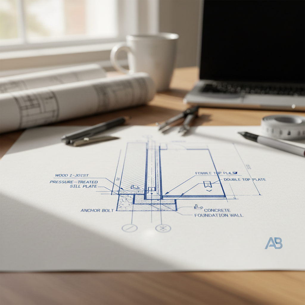
Every floor-to-wall framing connection in Alberta not only sustains gravity loads but also defends the home against the province’s significant wind and, in specific zones, seismic forces. The configuration and securing of these connections determine how well a structure resists lateral displacement, vibrations, and long-term settlement, making them pivotal in the longevity and safety of wood-frame construction. Improperly drafted or executed connections lead to pervasive issues: wall separation, persistent floor squeaks, uneven settlement, and even catastrophic structural failure under extreme conditions.
Detailed NBC(AE) 2023 Code Requirements for Floor-to-Wall Framing
Anchorage of Building Frames (Article 9.23.6.1)
Anchorage dictates how floor and wall assemblies are tethered to the foundation-a matter of more than structural routine in Alberta, where wind uplift and lateral earth pressures set substantial demands. Article 9.23.6.1 requires all building frames to be anchored unless a precise structural analysis demonstrates that such anchorage is non-essential, accounting for wind, seismic loads, and lateral earth pressures.
- Practical Implication: For typical Alberta single-family and duplex homes, anchorage is not negotiable. Expansion by addition or new custom infill designs must detail positive mechanical anchorage at concrete, such as anchor bolts and appropriate washers, spaced per code or engineering evaluation, to preclude shifting during high winds or frost-induced heaving.
- Drafting Consideration: The drafter must indicate anchor bolt size, spacing, edge distance, washer type (commonly 50x50mm plate washers for seismic compliance), and embedment into the foundation wall. Clearly referenced code notes and cross-sections ensure clarity for permit reviewers and on-site trades.
Nailing of Framing (Article 9.23.3.4)
The transfer of floor-system loads to the walls-and vice versa-relies on reliable mechanical fastening. Article 9.23.3.4 specifies prescribed nail types and spacings for bottom wall plates to joists, blocking, and subfloor assemblies. Effective nailing patterns guard against separation through seasonal movement and support the surefire distribution of imposed and dead loads.
- Exterior Walls: Bottom plate to joists or blocking requires 82 mm nails, spaced 400 mm on center. This robust pattern counters wind and building settlement, preventing floor sheathing uplift and wall misalignment.
- Interior Walls: Attachment to subflooring or framing at 600 mm on center with 82 mm nails reflects the reduced loading but still provides for shrinkage, vibration, and minor settlement.
On the drawings, this requires not only a callout of the fastener types and schedule but also clearly detailed intersections at sections and enlarged assembly views, making expectations explicit for framing carpenters and inspectors alike.
Support of Walls: Loadbearing and Non-Loadbearing (Article 9.23.9.8)
Subfloor intersection points with walls demand careful attention, as the difference between loadbearing and non-loadbearing assemblies affects the load transfer path. Article 9.23.9.8 sets minimum standards for supporting both wall types.
- Non-Loadbearing Walls Parallel to Joists: Support provided by the joist below or, if not possible, by blocking (min. 38x89 mm SPF) at intervals not exceeding 1.2 m. This not only supports gypsum finish and fixtures but also precludes floor deck flexing that can cause drywall cracks and door misalignment.
- Loadbearing Interior Walls Parallel to Joists: These walls must be backed by beams or additional joists capable of carrying the full live and dead loads transferred from above. Failure to detail this adequately risks over-spanned joists and potentially hazardous floor deflection.
Drafting these connections requires meticulously drawn framing layouts indicating joist direction, blocking locations, and referencing all load paths from upper stories to the foundation. Legible details enable engineers and framers to adapt as needed but remain compliant with code intent.
Anchorage of Columns and Posts (Article 9.23.6.2)
Columns and posts, critical in transferring loads from beams, upper floor walls, or concentrated loads, must not only rest plumb but must also be positively anchored against slippage. Article 9.23.6.2 insists on mechanical anchorage to the floor system and secured transfer to the supporting foundation or beam below.
- Real-World Practice: Post-to-beam connections typically involve approved post bases, metal straps, or custom-fabricated saddles, each detailed for manufacturer installation instructions and code compliance. Fastener type, quantity, and corrosion protection (especially in basements or near exterior walls) are crucial callouts on all sections and details.
- Drafting Note: Each post foot must be referenced in plan, section, and via installation detail, including anchor type, depth, and interface with subfloor. Redundant notes on the permit drawings forestall site confusion and inspection delays.
Advanced Drafting Practice: Integrating Code and Site Realities
Drafting code-compliant connections is not rote translation of code tables but the marriage of regulation with on-site physics, material realities, and buildability. While the NBC(AE) 2023 sets the minimum, achieving sturdy and easy-to-execute floor-to-wall connections requires an eye on both textbook details and tradesperson workflow.
Lumber Selection, Handling, and Its Impact
- Moisture Content Limits: All framing lumber should be grade-stamped with a maximum 19% moisture content at the time of enclosure. Excess moisture warps plates and studs post-installation, opening up fastener holes and weakening connections. Drafters must note “dry cup” requirements and reference manufacturer spec sheets if engineered wood is used (LVL, LSL, PSL, etc.), which behave differently under Alberta’s climatic swings.
- Species and Grade: Spruce-Pine-Fir (SPF) dominates Alberta framing, but higher loads at connections could demand select grades or supplementing with engineered wood. In plans, grades must be called out where higher capacities or reduced shrinkage is essential-such as in long-span assemblies or where wall height exceeds standard dimensions.
Fastener Specification and Field Interpretation
- Corrosion Protection: In areas prone to high humidity (e.g., basements, garages, or homes with high-performance building envelopes), specifying galvanized fasteners increases durability. Clearly list fastener length, gauge, head type, and required spacings for all connections, not just those at exterior wall plates.
- Coordination with Trades: Pre-site meetings or construction notes on the drawings about nail orientation and staged nailing (especially at corners and intersections to avoid splitting) can preempt common errors, such as missed blocking or under-nailed corners that will invite structural issues during Alberta freeze/thaw cycles.
Connection Detailing: From Sill Plate to Sheathing
Every intersection represents a transfer of forces-vertical, lateral, and torsional. Attention to these crucial elements improves long-term performance:
- Sill Plate Installation: Drafters must call out level, pressure-treated sill plates for all locations in contact with concrete, held down by anchor bolts of minimum 12.7 mm diameter, no more than 2.4 m apart, and within 300 mm of each end of each plate piece, as per code. Where seismic, wind, or expansive soils dictate, reduce spacing or specify additional hold-downs.
- Floor Sheathing Integration: To maximize diaphragm strength, wall sheathing should extend past the sill and lap the rim joist, fastened thoroughly at prescribed spacing. Annotate not just wall assembly but overlap depth and nailing schedule, ensuring energy efficiency (reduced air leaks) alongside structural performance.
- Blocking and Bridging: Especially at loadbearing wall locations, mandatory blocking between floor joists transfers load evenly and controls lateral displacement of joists. Indicate location, size, and species-not just a simple “block as required”-to prevent site-level ambiguity.
Code-mandated and Best-Practice Nailing Patterns: Subtleties and Field Guidance
Interpretation of Article 9.23.3.4 on nailing reveals the importance of on-center spacing: too far apart, and connections risk gapping and independent wall movement; too close, and wood splitting or overdriven fasteners reduce holding power.
- 82 mm Nails: This dimension typically refers to a specific common nail size (3 1/4” framing nails). Automated nailing with framing nailers must use equivalent shank diameter and head size, a frequent point of review during inspections-and a consideration explicitly flagged on construction drawings.
- Spacing and Offset: Drafters must note that, at corners and intersections, nails may be staggered for optimal holding without splitting the bottom plate. In complicated intersections-such as where multiple walls converge or at bearing points for stair stringers-increase density within reason, supplementing with screws or metal connectors if permitted.
Explicit drawings and fastener schedules, tailored for field readability, close the gap between code intent and site reality, heading off common deficiencies.
Load Transfer Principles: Understanding Joist Direction, Wall Alignment, and Floor Framing Integration
Truly code-compliant connections succeed not just in isolation, but in how they fit into the structure’s overall load path. Drafters must interpret floor joist plans in concert with structural layouts, aligning wall locations with joist or beam positions beneath for positive load transfer.
- Direct Support: Loadbearing walls should always stand directly over support: joists, blocking, beams, or bearing walls below. Staggered layouts, frequent in custom homes and renovations where room layouts shift, must be reconciled through strategic blocking, double joists, or dropped beams, all called out on the drawings.
- Bridging for Non-Loadbearing Walls: Where walls do not align with support below, provide bridging or specific blocking (with size, grade, and frequency detailed) to meet the code’s distance maximums. Unblocked non-loadbearing walls frequently sag and invite drywall or trim cracking, issues that rapidly devalue a home’s quality.
The Realities of Columns and Posts: Anchorage, Alignment, and Differential Settlement
Columns and posts often attract unique code scrutiny-serving as concentrated point-load transfer elements, their failure to anchor not only risks slippage but imbalanced settlement and callbacks for uneven floors.
- Column Bases: CBC(AE) 2023 expects robust anchorage via post saddles, adjustable bases, or steel straps mechanically fastened to concrete or beams. Drafts should call out model numbers or minimum load ratings for post anchors, especially on engineered wood columns or where posts are embedded in potential wet or corrosive environments.
- Shim and Level Tolerance: Levels and shimming should receive a specific note-e.g., “Gap between post and beam to be filled using steel shims, no wood wedges permitted”-to ensure post bases transmit loads fully and resist vibration-induced settlement. In basement locations or mudsills, galvanized anchors are strongly recommended and should be indicated.
The Building Envelope and Energy Performance: Integrating Connections with Energy Code Tiers
The advent of energy performance tiers in the NBC(AE) 2023 requires not just a structure that stands, but one that limits heat transfer and air leaks-even at the junctions of floors and walls. While Tier 1 remains the minimum, many municipalities and owners now require or incentivize Tiers 2 and above.
- Thermal Bridging Mitigation: The floor-to-wall intersection often serves as an unwanted thermal bridge. Advanced drafting must specify continuous exterior insulation at rim boards, insulated headers above plates, and gaskets or sealants beneath sill plates. Details should indicate insulation type, thickness, and installation method at rim joist zones-where energy loss is most acute.
- Airtightness Detailing: Mechanical fastener and framing connections need not impede air barrier continuity-explicit notes calling for “continuous sealant or gasket at sill plate to foundation interface,” and instructions for lapping building wrap with wall sheathing, maintain envelope integrity without undermining structure.
- Compatibility with Systems: As energy tiers rise, interaction between HVAC and the structure intensifies. Drafters must detail service penetrations (ducts, electrical, plumbing) with pre-drilled sleeves or notches in blocking, so that trades do not indiscriminately cut through critical connections or insulation during rough-in, thus maintaining compliance without compromising air tightness or load transfer.
In high-tier homes, drafters integrate lateral bracing hardware to avoid the need for solid sheathing-details like metal strap ties, continuous insulation brackets, or proprietary connection systems, with layout and fastening schedules appended. Shop drawings for high-performance products should be referenced by manufacturer and installation specifics.
Resolving Construction Challenges and Site Modifications
Even the best-drafted connections face alterations on the job site. Truss changes, late plan amendments, or coordination with trades can prompt the need for immediate field modifications. Foreseeing these common deviations, drafters can pre-empt construction delays and code rejections:
- Allowance for Site Adjustments: Include general notes authorizing minor field-verified modifications by engineer or architect, referenced to code and permit conditions.
- Clear, Layered Detailing: Provide both typical section details and unique “atypical” intersection layouts, particularly for corners, T-intersections, stair landings, and posts at floor openings. Mark up potential site alternatives: e.g., “If joists do not align beneath this wall, install 2x6 SPF blocking perpendicular to joists at 400mm centers for full wall length.”
- Plan Coordination: Cross-reference wall, structural, and mechanical plans with explicit callouts for every intersection, so that trades foresee conflicts and can resolve coordination issues on paper before materials are cut.
Inspection, Documentation, and Permitting: Setting up Success
Drafting compliant details is only half the battle; framing connections must pass the scrutiny of Alberta's authorities having jurisdiction (AHJ) during scheduled inspections to avoid costly delays. This elevates the importance of clean, detailed documentation:
- Key Drawing Notes: Each code-mandated connection-wall-to-floor, post anchorage, blocking support-should be flagged on building sections, plans, and detail sheets. Reference the pertinent NBC(AE) 2023 articles directly: e.g., “Install as per NBC(AE) 2023 9.23.9.8.”
- Inspection Checklists: Summarize code critical assemblies in a table or legend within the drawing set, making it easy for the municipal inspector and allowing supervising trades to pre-inspect before official review. This strategy is proven to smooth inspection and reduce rework.
- Field Photos and Reports: For complicated connections or in renovation/retrofit conditions, recommend or require photographic documentation pre-insulation. On larger or code-intensive projects, require confirmation by the structural or geotechnical engineer before closing up assemblies.
Case Examples: Connecting Code to Practice in Alberta Conditions
Grounding theory in practice, typical Alberta projects reveal the enduring value and pitfalls of code-drafted connections:
- New Custom Home, Calgary: At complex floor plans with offset wall lines and multiple stair openings, the drafter coordinated triple-joist blocking at every main floor loadbearing wall, integrating both nailing patterns and bridging schedules for code acceptance and field clarity.
- Garage Suite Additions: Retrofit and new garage suites, increasingly common in Calgary and Edmonton, often insert new load paths over existing framing. Drafters must detail new blocking and post anchorage over double joists, select fastener patterns for existing lumber (often dried and split), and indicate both code minimums and enhanced reinforcement to counteract unknown pre-existing conditions.
- Rural Walkout Basements: For homes built into a slope, foundation and sill plate anchorage must take account of uneven pressures and potential lateral earth loads. In these contexts, drafter notes for additional tie-downs and below-grade corrosion-resistant anchors short-circuit future inspection failure and settlement issues.
Cost Management and Value Engineering in Connection Detailing
Precise, code-driven connections need not inflate framing budgets. In fact, early-stage, clear drafting that highlights locations of high-demand connections-corners, shear walls, post bases-lets builders order materials accurately, cut down rework, and avoid over-building. Value engineering by drafters is not about reducing safety but about optimizing labor and material investment:
- Standardization of Details: Where possible, use repeatable details for typical floor-to-wall connections and post bases. Indicate where custom or engineered solutions are required, so both estimators and field staff can streamline installations with minimal custom cuts.
- Allowance for Growth and Alteration: Draft wall-to-floor intersections to accommodate future renovations or additions when possible, calling out anticipated locations for additional posts or blocking. This positions the home for long-term flexibility, a premium feature in Alberta’s growing secondary suite and basement development markets.
Emerging Trends and Innovation in Framing Connections
The rise of advanced wood products, proprietary connectors, and performance-driven construction influences code-compliant connections in Alberta:
- Engineered Lumber: LVL, LSL, and PSL increasingly serve in rim boards and engineered joists. Their higher density demands longer or stronger fasteners, which must be called out per manufacturer specification.
Drafters should coordinate with structural engineers to specify fastener approval, avoiding the “generic” nailing that risks inspection dispute. - Metal Connectors and Brackets: With high-wind code demands in some Alberta zones, metal hurricane ties, seismic brackets, or proprietary hold-downs are now routine even in residential applications. Details should reference installation instructions and include illustrations or manufacturer cut sheets for clarity.
- Panelized and Modular Construction: Detailing must consider connections that can be quickly assembled yet maintain code compliance, relying heavily on clear documented assembly order and standardized fastener or connector arrangements. This trend is set to expand in Alberta’s higher-density subdivisions.
Integration of Floor-to-Wall Connection Drafting With Overall Design Process
Successful residential floor-to-wall connection detailing begins early-during schematic design and persists through permit review and construction documentation. Coordination with structural engineers, mechanical planners, and energy consultants ensures not only that NBC(AE) 2023 requirements are met, but that each intersection is constructible, verifiable, and adequately specified.
- Early Load Path Analysis: Collaborate from the start to align major walls over supports and verify posts land on footings or beams. Where later changes arise-client-driven floor plan tweaks, conversion of space to habitable area-update connection details to reflect new loading and anchorage needs.
- Iterative Review: Review and redline connection details with framing and construction leads before finalizing permit drawings. This field-oriented review flags travel patterns (where workers can nail or anchor), clarifies tricky intersections, and pre-empts future conflicts.
- Ongoing Education: The drafter’s role is both technical and educational. Well-noted drawings, with code references and field guidance, educate less-experienced builders or installers, raising the overall standard in Alberta’s homebuilding industry.
Summary: The Hallmarks of Code-Compliant, High-Performance Floor-to-Wall Connection Drafting
Meticulous drafting of floor-to-wall framing connections unites the authority of the NBC(AE) 2023 with real-world constructability and future-ready residential design. Every framing plan and assembly detail should directly reference code requirements for anchorage, nailing, structural support, and post connection, while integrating energy code considerations relevant to the project’s required performance tier.
- Load Path Continuity: Ensure each wall and post has a direct, capable support path.
- Resilient Fastening: Specify nail, screw, or connector types, sizes, and spacings precisely as per code-and call out special requirements for engineered lumber or high-exposure environments.
- Thermal and Air Barrier Integration: Highlight sealant, gasket, or continuous insulation aspects in every connection detail exposed to the building envelope.
- Field-Ready Documentation: Provide enlarged, referenced connection details, code citations, and schedules to streamline inspection and builder comprehension.
For every Alberta home-new-build, addition, or renovation-thoughtful, code-referenced drafting brings peace of mind to owners, builders, and municipalities alike, ensuring a structure’s performance, durability, and compliance from the ground up.
Kingsway Drafting & Design ensures Alberta homes are drafted with code expertise, clarity, and lasting value in every connection.