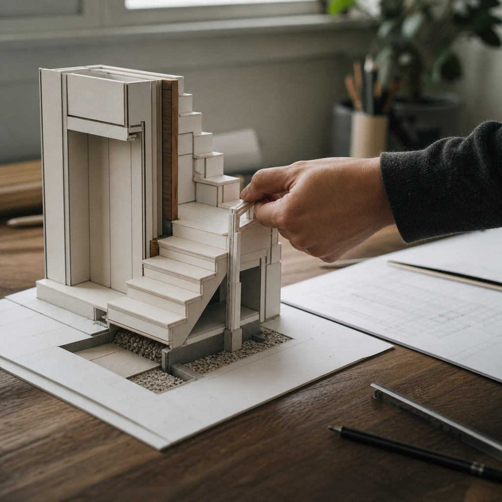
Concrete piers supporting exterior wood stairs and landings in Alberta must extend below local frost line-typically 1.2m in Calgary, 1.5m in Edmonton-per Alberta Building Code (ABC) 9.12.2.2, or plan reviewers will flag insufficient frost protection. From frost-protected foundations to precise ledger attachments, every detail on the sheet set-from lineweight to callout-directly impacts permitting and successful field assembly.
ABC-Compliant Frost Protection for Footings and Posts
Dimensioning Pier Diameter and Frost Depth on Drawings
The minimum depth for foundations in Alberta is determined by regional frost penetration and soil conditions, defined under ABC 9.12.2.2. In Calgary and southern Alberta, exterior stair and landing foundations must extend no less than 1,200mm (48"), while in Edmonton and most of central Alberta, that minimum depth increases to 1,500mm (60"). Plan reviewers frequently leave comments such as:
- "Frost depth on section does not match general note. Revise all sections/details-frost penetration in Calgary is minimum 1200 mm below finished grade."
Section views and foundation plans must dimension both the diameter and depth of each pier, commonly specifying diameters of 305mm (12") for standard loads, with increases up to 406mm (16") or the addition of bell bases (e.g., 508mm diameter x 150mm thick) where soil conditions or deck spans require. Sheet call-outs:
- Pier: 305mm Ø, min. 1200mm below grade (Calgary)
- Bearing: Undisturbed soil
Elevation markers must relate the bottom-of-pier elevation to project datum, ensuring excavators and inspectors confirm actual depth and bearing conditions in the field.
Concrete Mix, Air Entrainment, and Rebar Spec Notation
ABC 9.15.4 requires all exterior footings to be constructed with concrete at least 25 MPa at 28 days, with a maximum water-to-cement ratio of 0.45 and air entrainment between 5% and 8% for freeze-thaw durability-major in Alberta’s climate.
- Concrete: 25 MPa @ 28 days (CSA A23.1), w/c ratio max 0.45, air: 5-8%
Reinforcement must be shown in enlarged plan or section with typical rebar schedule: vertical #10M (Grade 400) bars, stirrups or ties as needed, minimum 75mm concrete cover in any direction for bars in soil contact. Omission of clear rebar callout in both cross-section and notes is a major plan-review trigger:
- "Rebar schedule missing-add typical vertical and stirrup bar, show minimum cover."
- "Material specification incomplete-concrete strength/air/cement ratio not stated. Add to notes and pier detail call-outs."
Post-to-Footing Connection Details and Drawing Call-Outs
Elevated post bases (e.g., Simpson ABU44Z, galvanized steel) must be used to separate wood posts from concrete and soil, addressing ABC 9.23.6 exposure criteria and preventing rot.
- Post base: Galvanized, min. 100mm above grade
- Anchor bolts: 12.7mm dia., min. 178mm embedment (7"); verify spacing per post base manuf. spec
Plan and section details should include:
- Enlarged detail-showing post bearing, base, anchor bolt, and elevation above surrounding grade
- Plan/tabular schedule: quantity, type, and location of each post and bracket
If the lateral bracing of tall posts is not indicated (e.g., diagonal 2x4 KD SPF at 45°), plan-checkers typically request:
- "Provide lateral bracing details for exterior posts exceeding 1.8m above grade - ABC 9.23.10.7 applies."
Undisturbed Soil Notation and Backfill Requirements
For bearing, the lower tip of the pier must reference "undisturbed native soil" in both section cut and schedule notes. Where backfill is present, ABC requires granular material compacted to 98% Standard Proctor Maximum Dry Density. Plan notes should clarify:
- "Pier bases to bear on undisturbed soil; compacted granular fill only where approved by engineer. Backfill with well-graded gravel, compacted 98% SPMDD."
Preempting Permit Redlines and Ensuring Complete Sheet Annotations
Universal review themes include missing frost depth callout, unclear concrete/rebar spec, and insufficient post base depiction. Standard drawing conventions include:
- Section tags with reference (A/A-301) indicating detail cut through footing/post
- Detail bubble-enlarged anchor bolt and standoff base at 2/A-501
- General notes referencing ABC 9.12, e.g.,"Foundation depth and detailing to comply with ABC 9.12.2.2; all deviations must be approved by designer and local Authority Having Jurisdiction."
- Material annotation directly adjacent to footprint symbol or in tabular schedule
By cross-referencing these elements-plan, section, schedule, and note-permits and construction are streamlined, minimizing RFI and field rework.
Exterior Wood Landing Drainage and Moisture Management
Deck Board Spacing and Slope for Rapid Drainage
ABC Section 9.26.1.2 and 9.14 require all exterior landings and decks to shed water away from the building. Sheet A-102 (plan view) must show minimum 3mm gaps between deck boards-critical for drainage-that allow rapid drying and expansion tolerance. Include annotation:
- "Provide min. 3mm spacing between all deck boards for drainage (ABC 9.14.1.3)."
Landing plans and framing profiles must show a consistent minimum 2% slope (1:50) away from the structure (i.e., 20mm drop over 1,000mm run). On stair side/elevation, indicate:
- "Landing/Deck: min. 2% slope away from building (20mm per 1,000mm, verify with level on site)."
- "All joists to be crowned and shimmed/oriented to achieve required slope."
Ground Grading, Post Standoffs, and Flashing
Site grading at footings must direct water away a minimum of 2% for at least 1.2m from the posts-detail in both site plan grade contours and section views:
- "Grade: 2% slope away from all posts/footings for min. 1.2m."
At all concrete/wood interfaces for posts, galvanized standoff post bases (minimum 100mm above finished grade) should be depicted in detail bubbles and section:
- Section 3/A-501: "Adjustable elevated post base (Simpson ABU44Z or eq.), galvanized, min. 100mm standoff above concrete."
For ledgers, continuous 26-gauge galvanized steel flashing must be shown in wall section and isometric detail:
- "Install continuous 26ga galv. steel flashing below ledger board, extending 150mm up behind siding, 50mm over ledger; lapped over house wrap per ABC 9.26.2.2."
For post penetrations through decks, flashing collars detailed at each cut must be provided; absence typically triggers:
- "Detail flashing at all post penetrations to prevent water ingress/per ABC 9.26."
Pressure-Treated Wood, Schedules, and Material Specifications
Wood elements in exterior landings or stairs, including any piece less than 150mm above grade, are to be specified in notes and schedules as preservative pressure-treated per CSA O80 Series-referenced in both material legend and Exterior Wood Stair & Landing Schedule.
- "All exterior wood posts, beams, and stringers within 150mm of grade to be pressure treated as per CSA O80, retention level appropriate for ground contact."
Failure to specify this in the general notes is a common plan review comment:
- "Specify preservative treatment for all wood elements less than 150mm above ground level."
Jobsite Verification and Plan-Review Comments
Details and section cuts should always include notes for jobsite slope and drainage verification:
- "Confirm 2% slope on all landings and decks after framing. Notify designer of deviations prior to cladding/finish."
Material symbol keys in plans must reference preservative-treated wood and correct flashing gauge/overlap at all junctions, reducing plan-review cycle time and field change requests.
Ledger Board and Building Connection Detailing
Ledger-to-Wall Connection: Section Details and Fastener Specification
Ledger boards supporting stairs or landings, when attached to framed walls, must utilize either 12.7mm (1/2") hot-dip galvanized lag screws or through-bolts. Fastener spacing is referenced to ABC (NBC(AE) 2023) Table 9.23.8.3.B. For up to 2.4m spans:
- Fasteners at 400mm o.c. staggered (W-pattern)
- Edge distance: 38mm min. from top/bottom of ledger
- End distance: 75mm min. from ledger ends
For concrete foundations, connection details must specify 12.7mm (1/2") expansion anchors or epoxy-anchored threaded rods, minimum 100mm down from the top of wall, spaced as above.
Drawing schedules must provide an explicit ledger attachment schedule:
- "Ledger Fastener Schedule: 1/2" HDG lag screw, 400mm o.c., staggered, min. 38mm edge distance, 75mm end distance."
- "For masonry, use 1/2" HDG expansion anchor/epoxy rod, min. 100mm embedment."
Typical permit review notes on incomplete schedules read:
- "Provide complete ledger attachment schedule-show fastener type, size, spacing, min. edge/end distances."
Continuous ‘Z’ Flashing: Detailing and Integration with House Wrap
Every ledger must be flashed to prevent moisture travel into wall assemblies, as required by ABC 9.26.2.2. The continuous ‘Z’ flashing profile (galvanized steel min. 0.33mm, aluminum min. 0.48mm, or vinyl min 1.02mm) must extend behind house wrap and lap 75mm (3") upward, 25mm (1") downward over ledger face:
- "Z" flashing: 26ga galv. steel, 75mm up behind housewrap, 25mm down; housewrap lapped over top leg, joints taped."
- Detail bubble 7/A-402: "Continuous Z-flashing: 26ga galv. steel, integrate with WRB per ABC 9.26.2.2"
All penetrations or splices require compatible sealant. Omitting clear integration sequence or flashing overlap is a primary reason for reviewer redlines:
- "Detail flashing installation at ledger-including integration with house wrap."
Clearances from Windows, Doors, and Utility Meters
Drawings must dimension a minimum 900mm horizontal clearance from ledger edge to windows/doors to avoid egress obstruction; a full meter (39”) clearance is required from gas and electrical meters (per utility regulations and ABC).
- "Landing edge to nearest window/door = 900mm min. Gas/electric meter clearance: 1000mm min."
Site plan and elevations should illustrate these offsets to avoid construction and inspection delays.
Sheet Integration and Plan-Review Comments
Section cuts and enlarged details must be coordinated, with identical call-outs in plan/section/schedules and code notation:
- "Refer to NBC(AE) 2023, Table 9.23.8.3.B for fastener spacing and type."
Reviewers frequently note:
- "Inadequate flashing detail-add section showing 'Z' profile and water-resistive barrier sequence."
- "Confirm all windows, doors, and utility meter clearances on plan."
Ledger board material, fastener schedule, and flashing spec must be physically present on both the detail and the project schedule for permit approval.
Guardrail, Handrail, and Stair Geometry Details
Stair Riser, Tread, and Headroom Dimensioning
ABC 9.8.4.1-9 controls stair geometry for both safety and accessibility:
- Single dwelling:
- Max. riser height: 200mm
- Min. tread run: 255mm
- Headroom clearance: 1,950mm min.
- Uniform rise/run: Within flight, max. 5mm variance; total range, 10mm
- Public stairs:
- Max. riser: 180mm; min. run: 280mm; headroom: 2,050mm
Section views must dimension all risers and treads explicitly, marking each with elevation spot grades.
- "Stair Riser: 190mm (typ.), Tread: 260mm (typ.), Headroom: 1970mm (min.)."
Reviewers typically comment:
- "Riser heights and tread depths are inconsistent; please revise to ensure uniformity within the flight."
Guardrail Post, Infill, and Connection Methods
ABC 9.8.8 requires guards when fall exceeds 600mm (24"). For stairs within dwellings:
- Guard height: 900mm min.
- Public: 1,070mm min.
- Post connection: Through-bolted or notched stringers, blocking as required-detailed in isometric and enlarged connection views (e.g., 4/A-504)
- Infill/baluster spacing: Openings must not admit passage of a 100mm sphere (ABC 9.8.8.4)
Baluster spacing must be dimensioned on the stair and landing elevations:
- "Balusters: 90mm o.c. (max.), 100mm max. clear (sphere test)"
Non-compliant infill or missing details result in redlines:
- "Guardrail openings exceed 100 mm; adjust design to comply with code requirements."
Handrail Size, Continuity, and Clearance Details
ABC 9.8.7.4 requires handrails between 865mm and 1,070mm above stair nosing-measured in section cut and elevation. Handrail profile must be continuously graspable, with a minimum 50mm clearance to adjacent surfaces (ABC 9.8.8.5). Cross-sectional details must dimension diameter (or perimeter if non-circular) and depth-to-wall:
- Handrail: 38-51mm diameter (typical graspable wood/metal), 50mm clear to wall
- Continuous, returned at ends
Detail 6/A-505: "Handrail: 45mm diam. maple, 50mm clear to wall, height 900mm above nosing, continuous along stair flight."
If handrail grip or height is absent in drawings:
- "Handrail height does not meet required range-specify between 865 mm and 1,070 mm above stair nosing."
- "Handrail not graspable profile-provide cross-sectional detail."
Materials and Fasteners
Wood: Pressure-treated for guards/stairs exposed to weather per CSA O80; handrails can be clear hardwood for interior or protected locations.
Metal: Hot-dipped galvanized (steel) or aluminum meeting strength standards (as per schedule and note).
All fasteners must be corrosion-resistant, matching manufacturer spec, and detailed in the connection schedule.
Plan-Set Integration and Annotation for Permit Review and Field Use
Best Practice Call-Outs, Notes, and Schedules
A consistent, concise annotation system links details to construction sequences and code references. Call-out standards include:
- Section cuts (e.g., 2/A-401 through each stair/landing)
- Detail bubbles (e.g., 3/A-502 at footing, 4/A-504 guard post connection)
- Elevation views for all guards/rails, keyed to main plans
General notes must cover code compliance, materials, and key construction practices. Example:
All exterior stairs and landings to comply with ABC 9.8.
Verify all field dimensions prior to fabrication.
All wood in contact with concrete/soil: pressure-treated CSA O80.
Slope all decks/landings at 2% min. away from structure after framing, verify before cladding.
Developing the Exterior Wood Stair & Landing Schedule
Tabular schedules support detailed instructions and reduce drawing clutter:
| Component | Specification |
|---|---|
| Stringers | 38x235mm (2x10) PT, 400mm o.c. |
| Treads | 38mm thick, 280mm run, non-slip surface |
| Risers | 19mm, closed design, max. 200mm height |
| Handrail | 45mm diam., maple, 865-1,070mm above nosing, continuous |
| Guard | 900mm height at stairs, 1,070mm @ landings over 1.8m above grade |
| Fasteners | HDG/s.s. as scheduled-deck screws, lag bolts, expansion anchors |
| Finishes | Exterior-grade stain/paint; powder coat (metal) |
Each symbol on the plan links to a note, detail, or schedule item for rapid permit review and trade reference.
Comprehensive Drawing Views and Code Reference Notation
Standard drawing sets include:
- Plan view: location, orientation, relationship to building
- Section: show rise/run, headroom, footing depth, ground slope
- Elevation: guard, handrail, infill spacing, landing detail
- Detail/inset: specific connections-stringer/landing, post/footing, ledger/house
Each view is cross-referenced:
- "See 3/A-501 for stair-to-landing connection"
- "ABC 9.8.4.2 applies: risers/treads as dimensioned"
- "Flashing per ABC 9.26.2.2-see 7/A-402"
Precise code notation (not simply "to code") and numbered views accelerate plan approval and resolve most field disputes.
Plan-Review Comments and Jobsite Verification
Plan reviewers routinely flag:
- Ambiguous connections or missing references-"Clarify connection details for stair stringer landing junction"
- Missing material/fastener spec-"Schedule call-out incomplete for handrail fasteners-confirm size/type"
- Missing jobsite check notes-"Add note to verify ground slope, stair geometry on site prior to cladding"
Drawing sets that respond to these themes in advance avoid permit delays, field RFIs, and contractor disputes.
Kingsway Drafting & Design ensures exterior stair and landing details in Alberta are dimensioned, annotated, and scheduled for trouble-free review, permit approval, and construction.