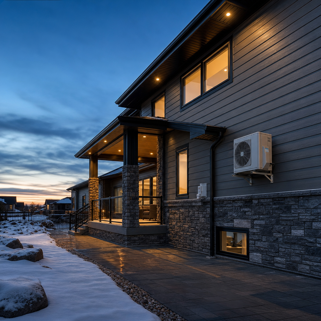
Exterior wall-mounted equipment-including HVAC units, satellite dishes, heat pumps, and mechanical vents-introduces unique drafting, review, and site coordination requirements across Alberta residential projects. The National Building Code - 2023 Alberta Edition (NBC(AE) 2023), effective May 1, 2024, governs structural supports, envelope penetrations, fire-resistance assemblies, and environmental separation for these installations. Efficient, code-compliant drafting begins with granular plan-details: blocking, load-path, and thermal performance all materialize as notations, call-outs, and detail sections tied to precise code references and local Alberta STANDATA guidance. Where plan sets fall short, project delays, field change-orders, and carry-forward deficiencies follow. Consistent, repeatable CAD/BIM conventions and robust documentation are not only best practice-they are often demanded by plan reviewers, enforced by inspectors, and relied upon by contractors in the field.
Structural Support and Load Transfer: Blocking, Fasteners, and Thermal Bridging for Wall-Mounted Equipment
Blocking and Structural Support: Plan Details and Code References
The NBC(AE) 2023 Part 9 addresses structural integrity for exterior wall-mounted equipment: Article 9.23.6.1 stipulates all anchorage must transmit the loads “safely to the supporting members.” While NBC(AE) does not prescribe exact blocking sizing, it is standard in Alberta to draft supports between studs using 38 mm by 89 mm (2x4) or 38 mm by 140 mm (2x6) lumber, depending on calculated load path and mounting hardware. For example, wall-mounted air conditioning condensers or small HRVs routinely require triple 2x6 SPF blocking at specific heights within stud cavities, shown in section and elevation views. Drawings should include a continuous call-out such as:
- “Provide 38x140 SPF No.2 blocking at mounting elevation for equipment support (see Detail 2/A402).”
Plan review redlines often note insufficient detail, e.g.:
- “Add blocking material, dimensions, and attachment schedule at mech penetrations (9.23.6.1; load path not clear).”
Fastener Specification: Materials, Sizing, Spacing, and Call-Outs
Article 9.23.3.4 of NBC(AE) requires “corrosion-resistant fasteners of sufficient size and number for their purpose.” For exterior penetrations, galvanized or stainless steel lag bolts are standard, with exact sizing often called out per manufacturer’s installation. A typical drafting notation:
- “(F1) Fasten bracket to blocking with galvanized 3/8" x 4" lag bolts @ 16" o.c.; min. 2 per mounting point.”
Reviewers routinely annotate:
- “Specify fastener type/size for condenser wall bracket, provide schedule if multiple types.”
On-site inspectors will check for adherence; substitutions (e.g., uncoated steel, improper diameter, excessive spacing) invite deficiency notices or stop-work orders.
Thermal Bridging: Detailing for Envelope Integrity
Thermal bridging, if untreated, undermines R-values and introduces condensation risks. The NBC(AE) 2023 Part 9 requires penetrations to maintain effective thermal resistance equivalent to adjacent wall assemblies. Standard solutions integrated into detail sections:
- “1/2" Neoprene thermal break pad between bracket and exterior sheathing.”
- “All through-wall bolts to be sleeved with insulation sheaths (R-value to match wall).”
Plan review may redline with:
- “No detail for thermal break at wall bracket-show insulation type, thickness.”
Thermal breaks are called out within section bubbles and schedules, ensuring clarity for both review and site trades. Standard material specification includes CRS (Code Reference Sheet) cross-referencing all such pads or insulated clips to their respective assembly and cut sheet.
Load Transfer and Assembly Notations
Assemblies must demonstrate a continuous load path from equipment to foundations. Section drawings should show blocking alignment with studs and rim joists, with notation such as:
- “Load transferred via blocking to bottom plate and joist below; coordinate with structural plan S-101.”
Dimension strings on plan sheets should indicate centerline-to-centerline spacing at blocking elevations, e.g., “EQUIP. BLOCKING CL @ 1525mm AFF (above finished floor).” Manufacturer anchor requirements, such as pull-out values, are sometimes tabulated in plan notes for clarity.
Integrated Flashing and Weather Barrier Termination: Sealing Wall Penetrations to Code
Flashing Requirements: Materials, Dimensions, Slope
Penetrations for equipment supports demand robust water and air sealing. NBC(AE) Section 9.27.3.1 mandates “a second plane of protection” and “flashing at all wall penetrations to direct rainwater outward.” Detailing starts with flashing materials, specified in Article 9.27.3.7:
- Galvanized steel: min. 0.33 mm thick
- Aluminum: min. 0.48 mm thick
Slope per Article 9.27.3.8 must be minimum 6% toward the exterior. Flashing should extend at least 50 mm upward behind sheathing membrane and overlap lower members by at least 10 mm. End-dams are required-with minimum height of 25 mm or 1/10 of wind-driven rain pressure, whichever is greater. The typical section reference:
- “Flashing: 24 ga. galv. steel w/ min. 50 mm upstand, 10 mm lap, 6% slope out, end-dams to 25 mm height-see Detail 5/A502.”
Material compatibility is essential (e.g., isolating aluminum flashing at masonry to prevent corrosion), called out in notes such as:
- “Isolate aluminum flashing from masonry with peel-and-stick membrane at interface.”
WRB and Air Barrier Integration at Penetrations
Drawings must illustrate the sequence of WRB and flashing installation, as incorrect lap order is a frequent reviewer and inspector concern. Enlarged detail bubbles (e.g., “Detail 9/A402”) should illustrate:
- WRB lapped over top edge of penetration flashing
- Sealant/adhesive bead at WRB/flashing mating edge
- Backer rod and high-performance exterior sealant at all equipment sleeves
Common plan review comments flag:
- “Flash expands equipment sleeve not continuous with WRB. Clarify WRB-penetration tie-in per 9.27.3.1.”
- “Provide detail showing sequence: WRB, flashing, sealant at vent stack.”
Drawing notes should be explicit on installation sequence:
- “Lap WRB membrane min. 75 mm over top edge of equipment sleeve flashing. Seal all fasteners with compatible mastic.”
Penetration Sealing and Material Schedules
Typical call-outs on detail sheets may read:
- “HVAC sleeve to be sealed all sides with high-modulus urethane sealant on backer rod-see Spec 07 92 00.”
- “Specify low-temp flexibility if using caulks (winter installation risk).”
Large penetrations (e.g., for mini-split pipes or HRV) often demand sheet-metal sub-flashing below the primary metal flashing, with both referenced by distinct detail bubbles for inspection clarity.
ABC Part 9 Compliance Documentation: Drawing Content, Review Criteria, and Code Citations
Required Drawing Information for Wall Penetrations & Support Systems
Section 9.10.5.1 of NBC(AE) 2023 governs permitted openings in assemblies requiring a fire-resistance rating and is frequently cited in plan reviews. All penetrations must be shown on plans, referenced to their fire-rated wall status:
- “A/C line set sleeve-3 hr. F.R.R. wall-fully intumescent firestopped, offset from outlets on opposite side per 9.10.9.8. See Detail 7/A603.”
Reviewers are likely to flag:
- “Identify all penetrations in rated assemblies. Show firestopping schedule per CAN/ULC-S115.”
When omitted, project holds or requests for supplementary enlarged details are standard reviewer practices. Fire-resistance requirements (manufacturer detail, ULC listing) must be called out at detail level and included in specification sheets; e.g., a firestopped pipe penetration on a party wall referenced as:
- “Guaranteed Firestop AS-PW-120 per CAN/ULC-S115, install per manufacturer’s instructions.”
Plan Review and Redline Triggers
Redline comments for penetrations frequently note:
- “Penetration cuts and schedules missing for exterior wall vents-update elevation and wall section.”
- “Call out required fire-resistance rating for all through-wall boxes and accumulative area (Art. 9.10.5.1).”
- “Structural impact of new mech units on load-bearing wall not shown-revise blocking support detail.”
Drawings for complex penetrations include isometric or exploded “penetration kit” details, with all assembly layers called out:
- 1-Eqpt. bracket
2-Neoprene pad
3-Firestop collar
4-Sub-flashing
5-Primary flashing
6-WRB wrap
Each assembly component is tied to a spec section (e.g., Spec 07 84 00 for firestopping, Spec 07 65 00 for flashing).
Material Specifications, Ratings, and Dimension Standards
Drawings and schedules must demonstrate compliance by explicit material call-outs:
- “Firestopping: Hilti FS-ONE MAX, ULC-catalogued for 2 hr. assembly as per UL system HW-D-0118.”
- “Sealants: Dymonic 100, exterior-grade, min. -40°C flexibility, applied over closed-cell backer rod.”
Blocking, fasteners, firestop, and insulation ratings are either shown in assembly diagrams or in tabular side-schedules directly beneath wall sections. Penetration sizes are dimensioned to be “No larger than 30 mm annular space around pipe per HVAC detail D3. Firestop to fill remaining gap to finish face.”
Drawing Sheet Mechanics and Standardized Details: Efficient, Repeatable CAD/BIM Practice
Layering, Line Weights, and Symbol Standards
For exterior wall-mounted equipment, leveraging the National CAD Standard (NCS) and, for Calgary, City of Calgary CAD Standard, ensures consistency and review transparency. Key conventions:
- Layer names: EQMT_WALL, PEN_FLASH, FIRE_STOP
- Line weights: Outlines 0.25mm, hidden/penetrations 0.15mm, call-out leaders 0.18mm
- Symbols: Anchor-filled triangle; penetration-hex with detail bubble (cross-referenced on sheet legend)
Call-outs must directly match legend/schedule nomenclature. For example:
- “(EQMT-3) Wall-mounted heat pump with blocking @ gridline D1, see Detail 17/A701.”
- “PEN-2” hex symbol at all wall sleeve penetrations; legend indicates “Type 2: 100mm insulated sleeve, full perimeter firestop Spec 07 84 00.”
Detail Referencing, Sheet Coordination, and Plan Schedules
Details for typical penetrations and supports are organized on standardized sheets-e.g., all equipment support details on A-502; all wall jacket/flashing/WRB tie-ins on A-504. Numbering is continuous project-wide:
- “Detail 12/A502-A/C Support w/ WRB Tie-In”
- “Section B/B @ 1:5-see for full sleeve/firestop/thermal break.”
For repeatable details: CAD/BIM blocks are stored in centralized firm libraries, with embedded specification call-outs and update logs. Each project substitution is identified in the revision schedule, ensuring that firm-level lessons on code amendments or frequent reviewer redlines quickly propagate across new drawing sets. Clash detection in BIM (Navisworks, Revit) is used to model actual equipment envelope/clearance impact, flagging conflicts early in the documentation phase.
Dimensions, Clearances, and Material Tags
Standardized tags and dimensions streamline review and field installation:
- “(E1.2) Typical A/C condenser: Mounting height 600 mm above grade, 150 mm from cladding face, 100 mm clear to adjacent vent.”
- “Blocking spacing: 400 mm o.c. max; equipment fasteners per anchorage schedule A13.”
- “Thermal break pads: 12 mm neoprene, R-value > 2.5 m2K/W.”
Dimensions for penetrations are referenced to finished floor and gridlines; all equipment and materials are scheduled in the “Exterior Equipment Schedule” indexed on the floor plan and elevations, with direct cross-reference to details and spec sections. Material compatibility flags (galvanic corrosion warnings, thermal break requirements) are embedded in keynotes and warning bubbles on details as a QA/QC mechanism.
Common Plan Review Deficiencies, Jobsite Call-Outs, and Remedial Detailing
Typical Plan Review Deficiencies and Reviewer Comments
Submission after submission, Alberta plan reviewers highlight predictable deficiencies for exterior wall-mounted equipment:
- Insufficient support details: “Show blocking size/type at all mech wall units-no attachment details provided (9.23.6.1).”
- Missing fire-resistance notations: “Penetration at east fire wall not detailed; lacks ULC assembly reference. Revise per 9.10.5.1, 9.10.9.8.”
- Omitted flashing/WRB detail: “Cladding cut for wall exhaust-no flashing or WRB sequence shown.”
- Unsupported equipment weight: “Provide confirmation wall type supports weight of equipment-supply engineering if over 115 kg.”
- Non-compliance with clearance: “Minimum clearance to door not met for wall heat pump, violates 3.6.2.2.”
On-Site Inspection Deficiencies and Field Call-Outs
Site inspections bring their own realities. Common deficiencies flagged by municipal inspectors:
- Use of interior-grade fasteners at exterior bracket (corrosion risk)
- Unsealed gap at WRB/equipment interface (visible water penetration)
- Improper or missing firestop material at rated assembly penetration (non-listed caulk or incomplete fill)
- Obstructions limiting code-required equipment service access
Remedial instructions from the field may direct, “Remove and reinstall mounting to add neoprene pad, fully sealed, per A502/Detail 12.” Inspector sign-off depends on as-built conformance with document detail and reference standards.
Remedial Detailing Approaches and As-Built Documentation
Addressing field issues begins with robust drawing conventions:
- All plan “clouded” changes referenced back to cause (“Remedial-Jobsite Deficiency 6/14/26, see Revision Note R7”).
- As-built addenda issued with explicit remedial sketches identifying deficient detail and corrective work.
- Updated detail and call-out for missed thermal break or weather-seal referenced on revision block and drawing issue sheet.
For future-proofing, details flagged in redline logs should be migrated back to template libraries, so recurring issues are addressed upstream in subsequent projects (e.g., “All wall eqpt. penetrations now include Detail 16/A504 standard WRB-and-flash wrap” per firm redline summary logs).
Dimensions, Ratings, and Material Specifications in Problem Solving
Effective plans anticipate field issues by explicitly tagging critical dimensions and performance:
- Equipment weights and mounting load values (e.g., condenser mass = 85 kg, wind load to 1.4 kPa)-tabulated with annotations.
- All fire-rated penetrations specified as “2 hr. F.R.R. per CAN/ULC-S115 listed assembly” with corresponding manufacturer and system ID.
- Flashing metals: “24 ga. galv. steel to 100 mm upstand, 6% min. slope out, continuous bead-sealed WRB lap at upper edge.”
- Sealant: “Tremco Dymonic 100, -40°C flexibility, applied over 19 mm backer rod, full perimeter.”
Clearance lines annotated directly on plan for field verification (“Maintain 950 mm min. clearance to nearest opening, ref. 3.6.2.2”). Where proprietary equipment or custom assemblies are used, shop drawings are provided with engineer’s stamp, referenced as “Supplied / stamped shop drawing for wall anchor system, attached as SK-21.”
Conclusion
Meticulous attention to plan sheet details, dimensioned call-outs for blocking and penetrations, WRB/flashing tie-ins, and assembly scheduling yields plans that sail through Alberta plan reviews and translate into robust, inspectable, and long-lasting installations-and in each case, code references (NBC(AE) section, CAN/ULC test, STANDATA interpretation) secure the drawing set’s defensibility. Kingsway Drafting & Design delivers Alberta projects with the depth of code-compliant detail that keeps projects moving from design table to successful inspection.