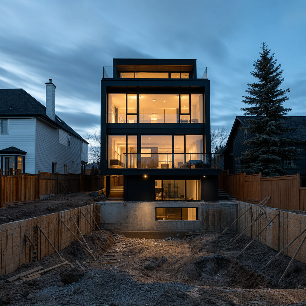
Excavation support and adjacent property protection are fundamental requirements in Alberta infill construction projects, showing up repeatedly during plan review, on drawing sheets, and at every stage of the build. Clarity and precision in call-outs, code citations, and detail annotation directly affect project approval, construction safety, and the stability of both new and neighboring structures.
Drafting Call-Outs and Notes for Excavation Support and Adjacent Property Protection
Alberta Building Code Article 4.2.5.2 directly addresses excavation: “Excavations shall be shored and braced as necessary to prevent caving or movement that may endanger adjacent structures, properties or the safety of public or workers.” This clause sets an uncompromising legal and technical expectation which must be reflected on all permit submission drawings and construction sets for residential infill projects.
Other pertinent code references include Article 4.2.5.3, requiring the support of excavation sides with retaining structures unless a professional design calls for something else, and Article 4.2.5.8, specifying backfill standards to mitigate post-construction soil movement. Most Alberta urban municipalities overlay these minimums with either municipal guidelines or permit application requirements, such as the City of Edmonton’s mandatory Project Implementation Plans (PIPs) or the City of Calgary’s specification-heavy infill plumbing and backfill instructions.
Essential Drawing Sheet Conventions on Foundation Plans
Plan sheets for infill construction in Alberta must visually communicate compliance with Articles 4.2.5.2, 4.2.5.3, and 4.2.5.8 via clearly referenced notes, cross-referenced detail tags, and explicit dimensioning. If excavation support is required by soil conditions or proximity to neighboring structures, it must be shown unequivocally on the plans:
- Typical Call-Out-Excavation Support: “PROVIDE TIMBER SHORING TO ALL EXCAVATION FACES WITHIN 1.2m OF PROPERTY LINE OR AS REQUIRED BY SOILS REPORT. SEE DETAIL 2/S-002.”
- Typical Call-Out-Underpinning: “UNDERPIN ADJACENT FOUNDATION USING 300mm THICK CONCRETE NEEDLE BEAMS AT 1.2m O.C. SEE DETAIL 4/S-003. VERIFY TYPE/DEPTH ON SITE.”
- Backfill Note: “USE NON-EXPANSIVE GRANULAR MATERIAL (SAND/GRAVEL, MAX 10% CLAY CONTENT) UNDER 95% STANDARD PROCTOR COMPACTION, PER ABC 4.2.5.8.”
- Adjacent Property Protection General Note: “CONTRACTOR SHALL PROTECT ALL ADJACENT STRUCTURES AND PROPERTY. COORDINATE MONITORING OF EXISTING FOUNDATIONS AND FENCES PER CITY OF EDMONTON PIP REQUIREMENTS.”
Code-Driven Placement of Notes and Details
All excavation support and neighboring property protection notes must appear in the foundation plan’s general notes, beside appropriate sections and on the detail sheets they refer to. Cross-referencing is non-negotiable: every note citing shoring or underpinning references a detail callout, and every foundation section showing an excavation face within 1.2m of a property line notes protection measures as per code.
Dimensions related to shoring must be called at minimum distances from the property line-commonly, any excavation within 1.2m requires explicit protection. Materials are noted with specific reference to standard ratings (“3X12 SPF No. 2 LAGGING BOARDS SPANNED OVER 150x150 STEEL H-PILES…”), and soil backfill notes specify compaction method and material classification, always referencing Article 4.2.5.8 for acceptability.
Typical Plan-Review Redlines and Field Deficiencies
Municipal plan reviewers routinely return redlines for the following:
- “Show all shoring or underpinning at basement walls adjacent to property lines.”
- “Specify backfill type and compaction for sideyard foundation walls per ABC 4.2.5.8.”
- “Detail measures to protect adjacent structures and fences during excavation.”
- “Missing general note regarding monitoring and protection of neighboring homes.”
In the field, these omissions often lead to enforcement orders, stop work notices, or neighbor complaints as lateral movement or improper shoring causes settlement or fence damage.
Detailing Excavation Support: Shoring, Underpinning, and Retaining Structures
Support for excavations is not a generic tab-in drawing note. Each infill lot, especially those with narrow sideyards and close neighboring buildings, requires location-specific details reflecting the anticipated soil conditions and actual site distances as derived from survey and geotechnical report.
Shoring for Vertical Cuts: Drawing Strategies and Call-Outs
For vertical or near-vertical excavation faces, as per ABC 4.2.5.3, temporary shoring must be drawn with both plan and section views, referenced in the schedules and general notes. Typical call-outs on plan will read:
- “STEEL SOLDIER PILES 200mm x 200mm @ 1.8m O.C. WITH 50mm TIMBER LAGGING. EMBED PILES MIN. 1.2m BELOW BASE OF EXCAVATION AS PER S-DETAIL 03/S-101. INSTALL PRIOR TO EXCAVATION ADJACENT TO PROPERTY LINE.”
Section views must illustrate:
- Excavation face with dimensioned offsets to property line.
- Horizontal tiebacks or bracing where needed, e.g., “60mm DIA. GALV. STEEL TIE RODS ANCHORED IN UNDISTURBED SOIL, MIN. 2.0m O/C.”
- Shoring material specs-species, grade and preservative if applicable, or steel shape and finish.
All shoring details are coordinated with foundation wall thicknesses and are tagged in the plan set wherever excavation approaches a lot boundary or existing structure. Dimensioning is precise: survey data showing exact offsets from property lines is referenced with “BC ALTA REGISTERED SURVEY,” not “approximate.”
Underpinning Adjacent Foundations: Notation and Detailing
Underpinning is triggered wherever infill excavation undercuts or otherwise endangers the bearing of adjacent, lower or older foundations.
- Call-Out Sample-Underpinning: “CONSTRUCT CONCRETE UNDERPINNING PADS 1.0m WIDE x 500mm LONG x 300mm DEEP @ 1.2m O.C. UNDER EXISTING FOUNDATION TO REMAIN. REINFORCE WITH 2-15M BARS TOP & BOTTOM. SEE 4/S-003.”
Underpinning details are given their own scaled section, showing separation between new and existing footings, material call-out for concrete (typically 32 MPa @ 28 days), and steel reinforcement. All separation distances and underpin width, depth, and lap lengths are dimensioned to the millimetre-reviewers in Edmonton and Calgary typically redline “dimension all underpinning width/depth/lap-DO NOT NOTE ‘TYPICAL’.”
Retaining Structures: Placement, Spec, and Integration
Where lot slope or protective measures call for permanent retention, retaining wall details are flagged with elevation and section tags. A typical call-out reads:
- “180mm THICK REINFORCED CONCRETE RETAINING WALL, 32 MPa, 400mm WIDE FOOTING, 10M @ 300mm EW, WATERPROOFING TO WALLS BELOW GRADE PER DETAIL 6/S-003. PROVIDE DRAINAGE BOARD, FILTER FABRIC, AND PERFORATED DRAIN AS SPECIFIED.”
Retaining walls are dimensioned for height above and belowgrade, referenced to survey datum. Their proximity to the property line, and the offset to existing neighboring structures, is called out to nearest tenth of a metre.
Adjacent Property Protection: Drawing Notes, Monitoring, and Zoning Impacts
Adjacent property protection, per ABC 4.2.5.2 and local municipal infill guidelines, must be addressed through layered specifications: buffer distances, monitoring, temporary protection, and-where required-public health and safety planning.
Protective Buffers and Fences: Call-Outs and Typical Dimensions
- “ERECT 1.8m HIGH CONTINUOUS PLYWOOD BARRIER ALONG NORTH PROPERTY LINE (0.1m INSIDE LOT), BRACED TO RESIST WIND LOAD PER OBC 4.1.5.5. MAINTAIN CLEAR ACCESS TO ADJACENT PROPERTY AT ALL TIMES.”
- “PROTECT ALL EXISTING FENCES, HYDRANTS, TREE ROOTS, AND LANDSCAPING PER CITY OF CALGARY TREE PROTECTION BYLAW AND INFILL POLICY.”
These notes are cross-referenced onto plan views and site logistics sheets, ensuring site personnel and inspectors have unambiguous instructions for setup and maintenance of barriers. Plans always indicate exact locations-property line by legal survey, dimensioned to the face of new fence or barrier-with notes such as “0.15m setback from surveyed lot line” or “barrier to be placed flush with existing fence.”
Vibration and Crack Monitoring: Specification Requirements
- “CONTRACTOR TO PROVIDE PRE-CONSTRUCTION SURVEY AND PHOTOGRAPHIC RECORD OF ADJACENT STRUCTURES. MONITOR FOR SETTLEMENT/CRACK DEVELOPMENT AT KEY LOCATIONS, AS DIRECTED BY GEOTECHNICAL ENGINEER.”
- “INSTALL VIBRATION MONITORING DEVICES WHERE REQUIRED WITHIN 2.0m OF ADJACENT FOUNDATIONS. PERIODIC RESULTS TO BE LOGGED AND KEPT ON SITE. REPORT ANY SETTLEMENT >5mm IMMEDIATELY.”
Plan reviewers increasingly demand evidence of monitoring protocols, with redlines such as “Add note to monitor cracking at adjacent concrete/brick-provide engineering procedure for remedial action if movement is detected.”
Acting on Local Bylaws and Municipal Zoning Impacts
Both Calgary and Edmonton overlay ABC requirements with municipal infill protection guides, including:
- Requiring PIPs (Edmonton): project-specific documentation signed off by professionals, outlining all excavation, temporary structure, and adjacent property protection steps, cross-referenced to municipal permit files.
- Site Disturbance Zones: designated no-go or limited-access sideyards along property lines, shown with hatch or shading on plans and coordinated with note: “NO STORAGE OR ACCESS WITHIN 1.2m OF PROPERTY LINE EXCEPT FOR APPROVED EXCAVATION SUPPORT WORK.”
- Utility and Street Protection: “CONTRACTOR SHALL VERIFY AND PROTECT ALL NEARBY UNDERGROUND AND OVERHEAD UTILITIES TO CITY OF CALGARY STANDARDS-SEE INFILL UTILITY LAYOUT PLAN AND MUNICIPAL SPECIFICATIONS.”
Zoning overlays and permit maps are referenced directly-“SEE DP #20XYZ, CITY OF CALGARY MAP 14N FOR AUTHORIZED ACCESS AND CONSTRUCTION LIMITS.” All such requirements are shown on plan sheets and coordinated in general and site-specific notes to avoid rejection for incomplete protection documentation at permit review.
Backfilling: Materials, Compaction, and Code-Note Coordination
Backfilling around foundation walls not only affects the new build’s durability but also plays a significant role in lateral property stability. Article 4.2.5.8 lays down the code minimum: all backfill must “provide adequate lateral support to the remaining soil and foundation wall and prevent soil movement that would be detrimental to any structure.”
Backfill Material Specification: Call-Outs per Alberta Building Code
- “BACKFILL WITH CLEAN, WELL-GRADED GRANULAR MATERIAL (SAND/GRAVEL, CL <10%) PER ABC 4.2.5.8. PLACE AND COMPACT IN 150mm LIFTS TO 95% STANDARD PROCTOR DENSITY. DO NOT USE EXCAVATED CLAY, ORGANICS, OR FROZEN MATERIAL.”
- “REMOVE SURFACE WATER AND EXCESS MOISTURE PRIOR TO BACKFILLING. SUPPORT ADJACENT FOUNDATION/FENCE AS PER SHORING DETAIL DURING BACKFILL OPERATIONS.”
Compaction and Placement Procedures: Dimensional Detailing
Detail sections must dimension backfill lifts, compaction equipment clearance, and offset from foundation wall. Standard drawing notes require:
- “COMPACT BACKFILL IN MAX. 200mm LAYERS USING PLATE TAMPER OR EQUIVALENT, WITH FIELD TESTING PROVIDED AS REQUESTED BY ENGINEER OR MUNICIPAL INSPECTOR.”
- “MAINTAIN MIN. 0.6m CLEARANCE BETWEEN BACKFILL OPERATION AND PROPERTY LINE FENCE TO PREVENT DISPLACEMENT.”
Plan reviewers frequently redline unclear section cuts or ambiguous notes (“Clarify backfill material under driveway approach-use granular base as specified, do NOT use site clay”). Field inspections will stop construction where unsuitable or uncompacted fill is detected within critical zones, especially close to adjacent property.
Showcasing Compliance at All Drawing Scales
Backfill notes and material specs must be shown at all scales where foundations interact with soil-plan, section, and detail-tagged back to general notes for coordination. Typical note format:
- “REFER TO GENERAL NOTE #8 FOR APPROVED BACKFILL MATERIALS AND COMPACTION REQUIREMENTS.”
As-built mark-ups and site notes sometimes require dimensioned sketch overlays showing compaction test points and cut/fill transitions, especially when infill is adjacent to older, less robust structures or retaining walls.
Redline Triggers, Common Pitfalls, and Correction Strategies
Municipal plan reviewers halt more infill projects for incomplete or ambiguous notes relating to excavation support and neighbor protection than almost any other issue. Actual reviewer comments from Calgary Bylaw enforcement and Edmonton Plan Examination regularly include:
- “Provide complete details for all temporary shoring within 1.2m of property line.”
- “Specify monitoring protocol and responsible party for adjacent structure protection.”
- “Clarify protection of trees and fences per City infill guidelines and ABC articles.”
- “Detail backfill material, method, and compaction-do NOT reference ‘by contractor’ only.”
The most common drawing oversights flagged for revision include:
- Omitting call-out details for shoring where excavation depth exceeds 1.2m adjacent to property line.
- Lumping all protection measures under a single generic note, instead of tagging specific areas.
- Leaving backfill and compaction methods vague (“Backfill as required”) without code-referenced specifications.
- Failing to dimension setback distances for temporary barriers or soil piles.
- Referencing standards (e.g. “per ABC”) without specifying article numbers, leading to time-consuming permit review cycles.
Correction strategies always involve adding explicit details, cross-referencing code sections (“ABC 4.2.5.2”), dimensioning all critical distances in plan, elevational and detail views, and providing notes stating which specialist (contractor, geotechnical engineer, etc.) bears responsibility for execution and monitoring.
Material and Rating Specification in Drawing Notes and Tables
Material specification tables are essential for clarity and sign-off by both engineers and reviewers. Alberta practice is to supplement general notes with tabular data indicating material grades, compaction percentages, reinforcement types and intervals, and permissible alternatives.
Typical Specification Table Excerpt
| Support Type | Material Spec | Dimensions | Performance/Testing |
|---|---|---|---|
| Shoring Lagging | SPF No. 2, Pres. Treated | 3x12 @ 1.8m span | N/A |
| Soldier Pile | W200x21 Steel, Galvanized | 200mm x 200mm, Embed 1.2m min. | Load test if >3.0m excavation |
| Underpinning | 32MPa Concrete w/2-15M rebar | 1000mm x 500mm x 300mm | Inspection by Engineer |
| Backfill | Sand/Gravel CL <10% | Placed in 150mm lifts | 95% SP Density |
Within general notes, direct code and standard references are always provided (“Material to comply with CAN/CSA-A23.1, ABC 4.2.5.8”). All variable items (“as required” or “by soils report”) prompt a cross-reference to a drawing schedule or engineering specification, not left open to interpretation.
Foundation Plan Sheet Integration: Coordination and Cross-Referencing
Effective integration of excavation support and property protection call-outs demands coordination throughout the drawing set:
- Site and foundation plans show excavation support strategies graphically, with tags like “SEE S-DETAIL 02/S-002.”
- Section and detail sheets unveil construction means-shoring, bracing, underpinning-with material, spacing, and dimensional requirements.
- General notes spell out procedure, code references, responsibilities, and referenced detail sheets.
- Specification tables backstop key notes and fix material/procedure ambiguities.
- Plan legend references all protection symbols and hatches, explaining intent (e.g., “Shaded area = access restriction, fencing to remain for neighbor protection”).
This cross-referencing ensures that site supervisors, inspectors, and trades can readily locate requirements without relying on verbal interpretation. Any material callout or detail connected to foundational stability or neighbor protection is explicitly noted with both code articles and municipal permit stipulations. Updates from addenda or change directives are tracked via clouded revisions on applicable sheets (FND, S, and GEOSTAB where applicable).
Examples of Alberta-Specific Drawing Notes and Redlines
Actual field-proven general notes, as accepted by Calgary and Edmonton plan reviewers, include:
- “ALL EXCAVATIONS WITHIN 1.2m OF PROPERTY LINE TO BE SHORED PER STRUCTURAL DETAIL. SHORING/UNDERPINNING TO REMAIN UNTIL SUFFICIENT BACKFILL & FOUNDATION WALL STRENGTH IS OBTAINED.”
- “MONITOR CONDITION OF ADJACENT FOUNDATIONS AND FENCES DURING EXCAVATION AND BACKFILLING. REPORT ANY DAMAGE OR MOVEMENT TO OWNER/ENGINEER IMMEDIATELY.”
- “CONTRACTOR RESPONSIBLE FOR PROTECTING UTILITY LINES AND INFRASTRUCTURE DURING EXCAVATION-CITY OF CALGARY REQUIREMENTS APPLY.”
Typical municipal redlines returned for insufficient notes:
- “No shoring/underpinning shown for west side. Revise plan to show all protection measures and detail specs.”
- “General notes missing monitoring protocols-add note for pre/postcondition survey and vibration monitoring.”
- “Add dimensioned distances from excavation to property line where less than 1.2m.”
- “Backfill note vague-must reference code article and material spec.”
Field Implementation: Translating the Drawing to the Job Site
Job sites depend on drawing clarity and completeness. Permitted plans, stamped by engineers and accepted by the AHJ (Authority Having Jurisdiction), guide excavation support, protective barrier installation, and underpinning in real time. Often, site staff refer directly to the section or detail sheets, matching notes and dimensions with field conditions.
Site signage is created from approved plan notes (“NOTICE: PROPERTY LINE SHORING REQUIRED, DO NOT REMOVE UNTIL ENGINEERING CLEARANCE”). Staging of materials, equipment, and soil storage aligns with shaded and dimensioned areas on site plans. City inspectors verify compliance by measuring from property lines to excavation faces, reviewing backfill material stockpiles for code suitability, and observing monitoring and reporting protocols as laid out in the plan’s general notes and tables.
Any deviation-underdimensioned shoring, lack of monitoring, placement of inappropriate fill-results in immediate review of the permit drawing, cross-checking notes and code call-outs before approving remedial work or stopping site activity. Final inspections require signoff that all temporary supports have been removed per note (“REMOVE ALL SHORING AND TEMPORARY BRACING ONCE BACKFILL COMPLETE AND FOUNDATION WALL STRENGTH VERIFIED BY ENGINEER”).
Conclusion: Drawing Excellence as the Foundation of Safe, Compliant Alberta Infill
Effective infill foundation plans in Alberta don’t just show walls and footings-they articulate, in measurable and code-cited detail, how excavation is supported and adjacent properties are protected at every stage. Reviewers expect clear, article-referenced notes, dimensioned detail call-outs, explicit material and compaction specs, and coordinated schedules-all structured to avoid ambiguity both in permit review and on the job site. In Alberta’s tight urban environments, precision in excavation support and neighbor protection drawings directly shapes both regulatory approval and construction outcomes.
Kingsway Drafting & Design delivers drawing packages that meet Alberta’s rigorous standards for excavation support and adjacent property protection, ensuring every infill project starts on a foundation of accuracy and compliance.