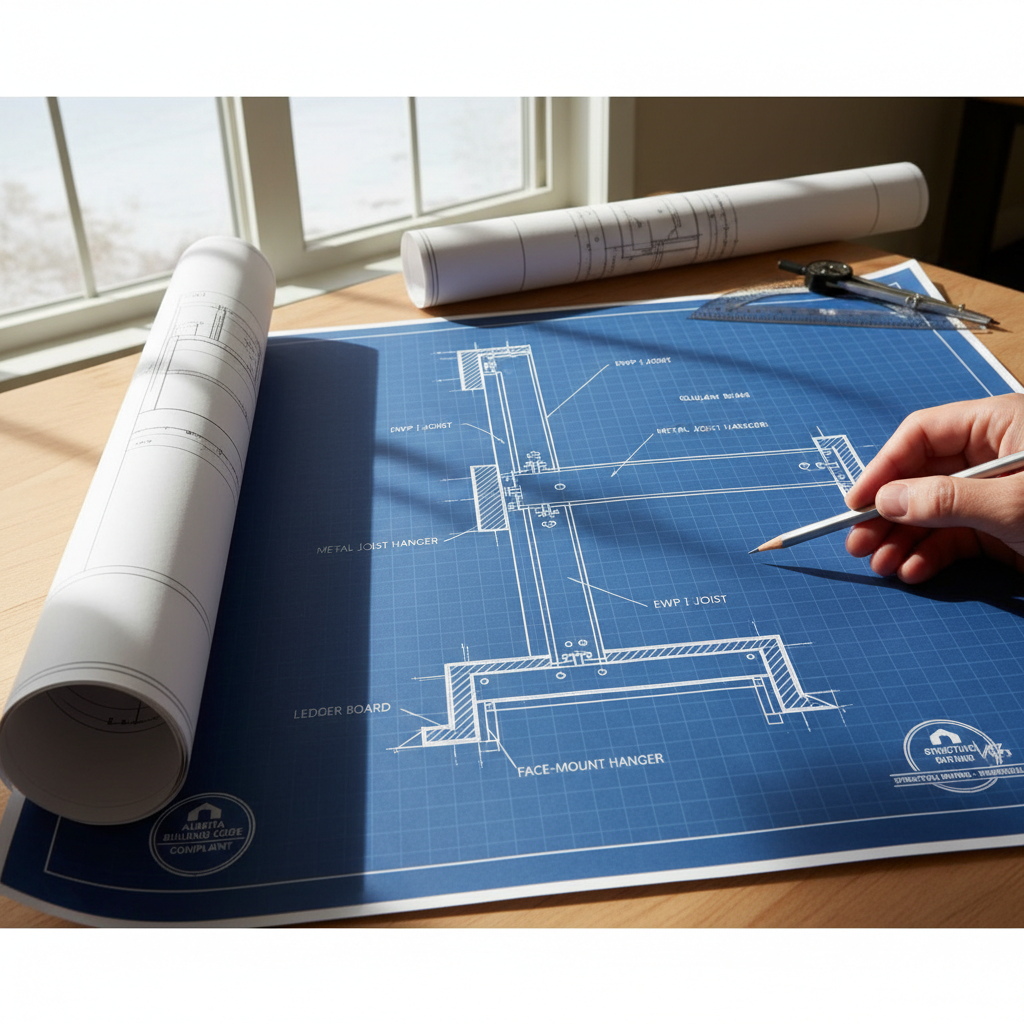
Engineered wood products (EWPs) such as I-joists, laminated veneer lumber (LVL), and glue-laminated timber (glulam) have revolutionized residential construction in Alberta by offering solutions for complex structural spans and modern architectural demands. Drafting their connections requires detailed understanding and precise application of the National Building Code - 2023 Alberta Edition, especially Part 9, to ensure safe, efficient, and long-lasting structures. Each EWP type brings distinctive attributes and design requirements, shaping how drafters must detail supports, fasteners, and tie-ins between structural members. Inaccurate drafting at this stage leads to costly field modifications, compromised structural integrity, or failed inspections.
Overview of Engineered Wood Products in Alberta Projects
I-Joists: Efficiency for Floors and Roofs
I-joists represent a dominant choice for floor and roof frameworks due to their engineered geometry. Their composition-top and bottom flanges of solid sawn lumber or LVL, connected by an oriented strand board (OSB) or plywood web-delivers high strength and predictable performance for longer on-center spacing and greater spans. The flanges resist compression and tension, while the web manages shear forces. I-joists mitigate issues of shrinkage, warping, and inconsistent quality that arise with solid wood. For Alberta drafters, this means less concern for serviceability issues like squeaky or uneven floors, provided end and intermediate bearing conditions are correctly detailed. The reduced weight simplifies handling and installation, but specific attention must be paid to web hole locations, web stiffeners, and precise end bearing dimensions as outlined in code and manufacturer specs.
Laminated Veneer Lumber (LVL): Precision for Beams, Headers, Rim Boards
LVL is manufactured by laminating thin wood veneers into a unidirectional assembly, giving it high strength and a consistent modulus of elasticity. LVL is chosen for point-load carrying beams, headers over large window or garage openings, and as rim boards supporting floor joist ends. Most manufacturers produce LVL in depths matching conventional lumber but with finer increments in thickness to fine-tune structural calculations. LVL’s predictable strength overcomes the natural variability of sawn timber, reducing the risk of performance deficits. This reliability, however, shifts the onus onto drafters to specify connection details that do not impair these favorable properties, including end bearing conditions, fastener types and placement, and moisture protection.
Glue-Laminated Timber (Glulam): Flexibility and Span Capability
Glulam utilizes multiple layers of lumber bonded with high-strength adhesives, allowing for large, sometimes curved, structural members. Glulam excels for longer spans, architecturally exposed beams, or curved roof and canopy structures. Its higher load-carrying capacity relative to its weight enables tall open spaces and large roof assemblies. For drafters, glulam connections-often requiring proprietary connectors-must be carefully coordinated with other trades and foundation details, accounting for additional considerations of load paths, potential movement, and exposure class. Alberta’s environmental conditions-freeze/thaw cycles, indoor-outdoor transitions-require close adherence to detailing best practices and code separation requirements to maximize lifespan.
Application of NBC(AE) 2023 Part 9 to EWP Connections
Conditions Permitting Use of Part 9 Provisions
The prescriptive provisions of Part 9 hold only when certain dimensional and use thresholds are not exceeded:
- The span of structural members must not exceed 12.2 meters;
- Repetitive members (joists, rafters, studs) should be spaced ≤600 mm on-center;
- Floor live load bearing does not exceed 2.4 kPa;
- The system is not a foundation or primary support for a critical assembly;
- Roof and wall assemblies must be sheathed/braced on at least one side, providing necessary racking resistance.
In practice, many Alberta single-family homes and low-rise projects fall within these limits, but high-end custom builds or small multi-family may not. If any limit is exceeded, a designer must defer to NBC Section 4.3.1, requiring full engineering.
Critical General Requirements from Code
Code directs that structural members are not only to be sized for load, but must be effectively framed, anchored, fastened, tied, and braced. This is especially important for EWPs given their unique loading patterns and sensitivities to fastener placement. For example:
- Moisture separation is mandated wherever untreated wood bears on concrete in direct contact with ground or fill-drafts must specify 0.05 mm polyethylene or Type S roofing between these elements.
- Fastening schedules must reflect the EWP manufacturer specifics, not just generic lumber standards, since EWPs often require more robust fastening due to their potential for splitting under concentrated loading.
Well-developed architectural drafting notes and structural callouts are crucial to relay these requirements to site crews-omitting detail at this level can precipitate failed field inspections or, worse, costly remediation if rot or movement develops post-occupancy.
Drafting Connections for Beams Supporting Floors
End Bearing: Foundation for Longevity
Beams require even, level bearing points, with end supports providing a minimum 89 mm (3.5 inch) bearing. Where beams interface with masonry or concrete, this detail becomes critical for both structural performance and moisture exclusion. Alberta’s severe freeze-thaw climate intensifies moisture risks at these interfaces-so it’s imperative in architectural drawings to denote the required polyethylene or roll roofing layer, preventing capillary water transmission into the wood. Neglecting this detail can hasten beam-end decay, especially in poorly insulated crawlspaces or basements, leading to differential settlement or floor sag within a few years of occupancy.
Built-Up Beams: Board-By-Board Detailing
Heavier structural demands-such as supporting large point loads from above-frequently lead to built-up beams, fabricated from multiple pieces of 38 mm thick lumber (commonly LVL or dimensional lumber) nailed or bolted together and installed on edge. The intricacies are substantial:
- Joints in the laminations should ideally bear directly on supports. Where this is not possible, the code allows offsetting joints at controlled quarter points-never with adjacent members jointed in the same location, and never exceeding a reduction of more than half the effective beam width in any section. This ensures continuity and prevents localized failure under load.
- For nailing: two rows of 89 mm (3.5 inch) nails, maximum 450 mm apart, with end nails precisely 100-150 mm from member ends-accurate drafting symbols and fastening schedules must reflect this. Correct nail placement is essential: skewed or misaligned nails can split LVL or glulam, especially at edges.
- Bolted connections: If selected instead of nails, call out 12.7 mm (1/2 inch) bolts with washers, spaced ≤1.2 m. End bolts must be ≤600 mm from member ends. Oversizing bolt holes, omitting washers, or inconsistent bolt spacing concentrates load, risking local crushing or slip. Draw details at beam ends and splice joints to clarify these requirements for site workers who may otherwise default to field improvisation.
Practical Implications
Improper jointing, skipping bolts/nails, or neglecting beam nailing patterns directly undermines structural integrity. For engineered products, the manufacturer's literature often supersedes code: for instance, some proprietary LVL beams require altered fastener patterns due to adhesive type or veneer layup. Incorporating explicit notes in floor framing plans-such as “All LVLs nailed as per XYZ Manufacturer Schedule”-avoids ambiguity. Similarly, visually distinct detail bubbles or callouts ensure the trades understand when standard wood nailing or bolting does not apply to engineered products. For multi-ply glulam beams, consult the supplier for specific dowel or through-bolt sizing and layout, since excessive or poorly located mechanical fasteners can lead to splitting and downgrading of capacity.
Drafting Floor Joist Connections: Prescriptive and Engineered Considerations
End Bearing for Floor Joists
Floor joists, regardless of material, require a minimum 38 mm end bearing-critical when EWPs such as I-joists or LVL are used, as insufficient bearing length can rapidly crush flanges or webs under residential loads. At interfaces such as ledgered exterior rims or internal beams, drafters must accurately show not only the required bearing but the support type: for example, ribbon boards let into studs must measure at least 19 mm by 89 mm and be denoted as continuous in elevation and section views. Oversights here can cause differential settlement along the floor deck, resulting in telegraphing floor issues to finishes and, in severe cases, requiring complete floor disassembly for repair.
Joists Supported by Beams: Framing and Hangers
Joists may bear atop beams or, more frequently with I-joist systems, are framed into the side of beams. For side framing, the code provides two standardized pathways:
- Joist Hangers: Must be proprietary, with ICC or CCMC approval, and sized for the specific flange width and depth of each EWP used. Some I-joists or LVL flanges are prone to splitting unless the hanger seats and nailing angles match manufacturer specs. Drafted plans must indicate hanger type, fastener schedule, and-where specified-web stiffener presence. Skipping this specificity in drawings can lead to unintended use of generic hangers, which may inadequately support the load and void manufacturer warranty.
- Ledger Strips: Minimum allowed size is 38 mm by 64 mm. For 38 mm by 38 mm ledgers, Alberta code requires at least four 89 mm nails at every joist, in addition to nailing the ledger continuously to the beam. For modern EWPs, drafters must verify whether ledger attachment is permitted-many EWP guides restrict or prohibit nailing ledgers into flange sections, necessitating alternate support methods.
At every connection, drafters must clarify in their details whether joists are to be toenailed, face-nailed, or hung with mechanical hardware. These details are typically provided as part of the manufacturer’s shop drawing submittal, but architectural drafters bear responsibility for translating approved engineered intent onto permit plans-ambiguity is a common cause for field inspection failure.
Restraint of Joist Bottoms: Preventing Lateral Instability
To prevent floor bounce, squeaks, and rotation, Alberta’s code requires restraint at the bottom edges of floor joists at spacings of no more than 2.1 meters. This can be accomplished by:
- Solid bridging: blocking between joists, typically with 2x wood or engineered blocking panels.
- Cross-bridging (diagonal bracing): where allowed by the EWP manufacturer, angle braces securely connected to joist flanges.
- Continuous rim board or band joist: EWP-compatible materials manufactured for this purpose provide rigid ends and attachment points for exterior sheathing; critical for lateral strength and transfer of wind loads.
For I-joist floors, manufacturer details may require specific nailing, screw attachment, or even glued connections between joists and bridgings to prevent vertical and horizontal movement. These details must be referenced directly on the plans, as field crews often default to traditional solid blocking methods which are inadequate for some I-joist and LVL systems, given different fastener holding strengths and vibration characteristics. Contact points between EWPs and solid wood should be detailed with moisture barriers when over unconditioned crawlspaces or adjacent to exterior walls.
Drafting Code-Compliant EWP Connections: Practical Expert Guidance
Manufacturer Specifications: Beyond the Code
Manufacturer installation manuals and shop drawings are non-negotiable references for EWP drafting. Unlike dimension lumber, each EWP line features proprietary adhesive chemistry, fiber orientation, and sometimes, unique composite behaviors under load. Local distributors routinely circulate updated connection schedules and detail sheets. For example, I-joists from Weyerhaeuser, LP, or Roseburg each specify exact fastener size, type (nail, screw), and pattern-substituting one for another can invalidate load ratings or lead to call-back repairs under warranty. Drafting offices should maintain reference libraries of these guides and annotate plan sets or connection details with explicit cross-references, ensuring field traceability.
Fastener Compatibility: Avoiding Corrosion and Failure
Alberta’s changing moisture and temperature levels, especially where EWPs interface with concrete, treated lumber, or exterior elements, pose fastener corrosion risks. EWPs treated with fire or preservative chemicals may require special fasteners-galvanized or stainless steel. Glulam beams exposed in the exterior envelope require hidden or semi-hidden connectors detailed with corrosion-inhibiting finishes. Drafted notes must specify not only fastener type, but coating or finish, and direct the builder to reconcile with manufacturer requirements. Overlooking this step leads to early connector corrosion and potentially catastrophic connection failure, especially in highly loaded connections such as deck beams or covered porches.
Load Calculations: Detail Drives Performance
Accurate load tabulation underpins every drafting act-span, spacing, tributary area, and concentrated load points structure which EWP size and connection method is selected. For Alberta’s increasingly complex home designs-multi-levels, open plans, large glass walls-concentrated loads on EWPs should be broken out in analytic schedules on the plan set, referenced at every major connection. Drafted details must provide clarity on joist hanger selection (with exact model or load rating), fastener count per connection, web stiffeners or blocking as required, and unique flange or web reinforcement when adjacent to plumbing, HVAC, or stair openings. Absence of these specifics is a common cause for field rework and delayed occupancy.
Moisture Protection: Defensive Drafting for Harsh Climates
Because of Alberta’s pronounced wet-dry, freeze-thaw cycles, aggressive moisture exclusion detailing is essential. EWPs exposed to repeated wettings, as in unvented crawlspaces or at poorly flashed deck ledgers, will degrade-compromising structural safety and potentially requiring entire framing replacement. Architectural drafts should denote the following for every EWP connection to concrete or masonry:
- 0.05 mm polyethylene strip, with width clearly noted, at every wood-concrete interface below grade or in vented crawl;
- Metal flashing or capillary breaks on exterior-exposed beams or rim boards;
- Air and vapor control layers at exterior rim boards properly lapped and fastened, reflecting wall assembly and window/door cutout sequencing, to ensure no moisture intrusion at these critical transitions;
- Ventilation notes for rim joist cavities, especially in heated spaces above garages, to avoid condensation trap;
- Detailing furring or airspace when EWPs are within the thermal envelope adjacent to unheated spaces, to prevent temperature-driven vapor transfer.
Further, for exposed glulam or engineered beams, indicate special end-seal paint or manufacturer-recommended protective tape to be applied after field trimming.
Prescriptive Versus Engineered Solutions: Understanding the Thresholds
Many Alberta homes utilize the prescriptive path for EWP connection, but several situations trigger the need for custom engineering outside of Part 9:
- Spans exceed 12.2 m or joist/rafter spacing exceeds 600 mm.
- Loads surpass 2.4 kPa (e.g., for heavy stone floors, commercial conversions, or rooftop patios).
- Innovative assembly types that defy prescriptive tables, such as double cantilevered decks or multi-storey stacked wood construction.
- Use of proprietary EWP products without an explicit CCMC or code evaluation report.
Drafters must train their eye to spot projects approaching these limits. Close coordination with a structural engineer becomes mandatory at schematic design for such structures. If in doubt, proactively flag in the plan set "Engineered design required for all spans and connections exceeding prescriptive limits." Authority having jurisdiction (AHJ) officials in Alberta can-and frequently do-reject permit sets lacking this clarity, especially as Part 9 boundaries are pushed in boutique home design.
Common Field Failures and How to Prevent Them Through Superior Drafting
Insufficient End Bearing and Connection Detailing
One of the most frequent remediation requests on Alberta sites involves EWPs trimmed too short for required bearing. For I-joists or LVL end supports, failure to mark the minimum bearing length and substrate prep on drawings-especially for concrete or block supports-leads to installers "making fit" without regard to code minimums. Drafts that indicate, for example, a shaded or colored "bearing zone" on beam seats, complete with required moisture separation protocol, set site expectations clearly. Enlarged details for complex junctions-such as intersecting beams, step-downs at sunken living rooms, or over-widened stair landings-pay dividends here.
Fastener Mis-Specification
Generic "nail as required" or absent fastener notes are a leading cause of insufficiently anchored EWP connections. The problem compounds when converting American supplier specs to metric code or vice versa. Alberta drafters must always provide a fastener schedule by EWP type and junction type, shaded on plans and keyed to each room, especially at high-stress points like stair stringer pockets, roof ridge beams, and floor-to-wall rim board transitions. Annotate plans with reminders about matching specified fastener type (e.g., galvanized or stainless when adjacent to treated materials/potential high moisture exposure). For screw connections, include torque or predrill requirements as per manufacturer. Show in section every situation requiring web stiffeners or blocking materials, otherwise field crews will commonly omit these.
Lack of Bridging or Rim Board Clarity
Floor vibration, rotation, and long-term performance degrade dramatically when bottom bridging, blocking, or continuous rim boards are omitted or inadequately attached. For plans showing large areas of clear span (great rooms, bonus rooms, etc.), drafters should highlight bridging placement, connection type, and schedule (material, nailing/gluing, angle) in plan view, cross-section, and an enlarged detail. Add notes specifying which products can/can’t be trimmed in the field for blocking-many I-joists only permit manufacturer-supplied blocks for lateral restraint due to web strength limitations.
Improper Coordination of EWP and Solid Lumber Connections
Transitions between EWPs and traditional lumber-such as at stair openings, around fireplaces/chases, or for framing around HVAC/plumbing-are a notorious site problem point. EWPs may not accept traditional face-nailing or toenailed blocks without splitting or crushing. Drafts should show hardware transitions: metal angle brackets, hangers, or specific reinforcement blocks, labeled by manufacturer and model type, to prevent field improvisation. Where field trimming is allowed, note restricted cut/out zone as per EWP manufacturer-improvised cuts void warranties and can accelerate decay if end-painting is not specified.
Implementing Robust Drafting Processes to Ensure EWP Connection Compliance
Reference Library: Maintain Up-to-Date Manufacturer and Code Data
Successful Alberta drafting offices create and routinely update in-house reference binders or digital libraries for every major EWP type and supplier. These include fastener schedules, allowable modification charts (holes, notches), connection details, and code digests. Each new plan should be crosschecked, especially after code revisions or manufacturer updates (such as the NBC(AE) 2023), to ensure no obsolete details are carried forward. Regular continuing education and supplier presentations help keep drafters informed of the latest innovations and warranty requirements.
Detail Libraries: Comprehensive, Scalable, and Clearly Call-Out
Building detail libraries of connection types-beam-to-post, joist-to-beam, hanger details, blocking/bracing-allows rapid repetition with project-specific customization. For each project, populate drawings with detail bubbles referencing these libraries while tailoring to each EWP’s exact size, type, and exposure context. Colored, shaded, or iconographic symbols in CAD sets can drastically reduce site install errors, especially when coordinated with field mockups and preconstruction meetings. Always accompany each detail with concise notes regarding moisture barriers, fastener size/type, spacing, and web/flange protection for cut or drilled ends.
QA/QC and Peer Review: Critical Before Submission
A final review by a senior drafter or structural consultant prior to permit submission catches most common errors or ambiguities. Items to check include:
- Are all EWP connections matched to their manufacturer’s load and installation table?
- Is every EWP-to-foundation or -to-masonry junction assigned a moisture separator?
- Are fastener types called out for environmental exposure and compatibility?
- Is bridging/blocking specified and coordinated with mechanical/plumbing/electrical penetrations?
- Are field modification notes provided where manufacturer’s cuts/trimmings are permissible, and end treatments clarified?
Permit reviewers in Alberta increasingly scrutinize these points-not only for code compliance but to avert warranty disputes and post-occupancy performance claims.
Special Considerations for Multi-Family, Infill, and Renovation Use of EWPs
Multi-Family and Townhouse Framing
In attached dwellings, acoustic and fire-resistance requirements frequently intersect with EWP floor and roof assemblies. Drafters must show connection details that maintain fire/sound rating continuity from wall to floor/ceiling to wall, including specific callouts for resilient connectors or isolation materials compatible with EWPs, rim board details at demising walls, and proprietary sealants where required. Sometimes, fire-treated EWPs require non-standard fasteners or greater separation from hot surfaces-call these out clearly in every connection detail, including transfer details between fire separations and exterior decks or balconies.
Infill and Addition Projects
Blending EWPs with existing lumber framing is routine in Alberta’s active infill market. Address differential deflection in connection details, as new EWPs may out-perform existing sagging or shrinking joists/beams. Where existing bearing surfaces are uneven, call for shim details of compatible, preservative-treated materials, and detail flashing for beam/joist terminations exposed to older, potentially leaky foundations. Where existing framing is not code-conforming (e.g., insufficient bearing length or spacing), draft clear corrective notes and defer to engineer sign-off as required by the AHJ.
Renovation and Retrofit
Retrofitting older homes with EWPs, particularly for open-concept conversions or large window/door additions, brings unique challenges. Often, drafters must resolve alignment of new EWPs to misaligned or out-of-plumb existing structures. Where tolerance stacking could impact performance of EWP connections, consider adding enlarged elevation or section details to coordinate trims, blocking, and shimming. For floor systems, specify where leveling compounds or non-combustible pad materials may be used to create true bearing for EWPs. Add supplemental instruction regarding field-applied end-seal or preservative where cuts are needed in confined, previously enclosed spaces.
Interfacing EWPs with Other Structural and Envelope Systems
Structural Insulated Panels (SIPs), Steel, and Concrete Connections
For hybrid assemblies, detail the interface between EWPs and SIPs, steel columns, or cast-in-place concrete. Show necessary connector hardware-specially coated hangers, angle brackets, or EPC-rated screws-for joining EWPs to dissimilar materials. Clearly note non-conductive break layers where EWPs are adjacent to steel and must avoid condensation. When EWPs bear on ICF or block walls, call out the type, thickness, and installation of separation membranes, as well as anchor bolt placement through the EWP for positive tie-back.
Thermal Bridging and Air Barrier Detailing
Rim boards and headers of LVL or glulam commonly sit at critical junctures of the thermal envelope. Plans should indicate continuous insulation, air/vapor membrane overlaps, and any interruptions needed for anchor bolts or through-hardware. Blocking and bracing details should reflect insulation continuity, and notes should specify compatible air barrier tapes and sealants for EWP adhesion or transition to other building materials. For multi-storey buildings, detail vertical alignment of rim boards for window/door openings to minimize cold-bridging at these sensitive nodes.
Field Coordination: Turning Drafted Connections Into Safe Construction
Builder/Trade Clarification Meetings
Because of the complexity of EWP systems, a best practice is to hold pre-construction meetings with builders and framing crews, using the drafted details as discussion guides. Walk through key areas-bearing details, hanger specs, web stiffener usage, and specific moistures protection steps. Distribute one-line summaries or laminated connection detail sheets to site supervisors, reducing the risk of field improvisation. These meetings help reinforce the message that drafted details are not recommendations but requirements for code and warranty compliance.
Site Inspections and Field Review Notes
Add in field notes to plan sets, such as “Review with EWP supplier prior to installation” or “Do not site modify without engineer/manufacturer approval,” especially at beams/joists in complex assemblies. Specify in notes which critical connections must be visually inspected and signed off (by engineer or building official) before enclosure. Leverage photo documentation at the time of installation for quality assurance, providing feedback for subsequent design improvement.
Conclusion: Delivering Safe, Compliant, and Efficient EWP Connections in Alberta
Drafting code-compliant connections for engineered wood products in Alberta means blending precise application of the NBC(AE) 2023 with in-depth product knowledge, attention to detail, and anticipation of field conditions. The most successful drafting brings clarity, foresight, and explicit instruction to every plan set, tailoring connection details to each product’s requirements and the realities of Alberta’s variable climate, inspection regimes, and construction practices. Robust drafting not only safeguards structural performance and occupant well-being-it minimizes costly site errors, shortens closing timelines, and builds reputation with both builders and regulators.
For quality-assured, code-compliant residential drafting in Alberta, Kingsway Drafting & Design sets the standard.