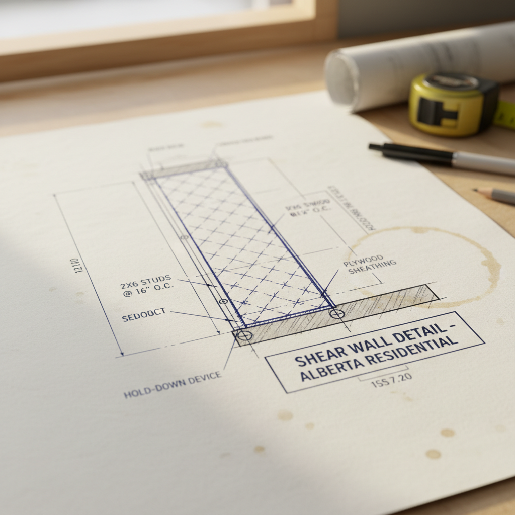
Shear walls act as the backbone of lateral stability in wood-frame housing, transferring horizontal forces-such as those imposed by high prairie winds and infrequent but code-considered seismic events-to the ground with predictable reliability. In Alberta, the open landscapes and rapidly changing weather can generate substantial lateral forces; improperly designed or detailed shear walls risk catastrophic racking, distortion, and even collapse. The precision of the architectural drafter’s detailing is therefore paramount-not simply for code compliance, but for the protection of property and life.
Racking is the unintended shifting or distorting of a structure, characterized by parallelogram-shaped deformation under lateral load. Shear walls combat this effect by acting much like the side of a box: as rigid planar elements, they resist forces that push or pull across the plane of the wall. When detailed and constructed correctly, these elements become invisible guardians within the envelope of a home, providing peace of mind through invisible performance.
Key Code Mandates: NBC(AE) 2023 Part 9 Provisions for Shear Walls
The 2023 Alberta Edition of the National Building Code mandates very specific conditions under which Part 9 applies-these define the scenarios in which wood-frame construction techniques, including shear wall design, are legitimate for use in housing and small buildings. For drafters, understanding these prerequisites isn’t just an exercise in regulatory navigation but a fundamental boundary of their day-to-day practice. The code applies when wall, floor, and roof framing comprises small repetitive elements (such as 2x4 or 2x6 wood studs spaced no more than 600 mm on center), loaded no more than 2.4 kPa live load, and when no member exceeds a 12.2 m span. Step outside these parameters, and the designer enters the world of Part 4 engineering.
Within these parameters, the code provides a prescriptive-yet nuanced-framework. Compliance hinges on the careful implementation of braced wall bands and panels, sheathing specifications, connection details, and continuous load paths. Each of these elements is interconnected: failure at the drafting stage to account for even a small oversight can result in costly delays, field modifications, or, worse, inspection failures.
Braced Wall Bands: Location, Configuration, and Responsibility
Braced wall bands are vertical “strips” of the building plan-full storey height and up to 1.2 m wide-running the breadth or width of the home and aligned on corresponding floors and roof levels. In effect, these create a grid or skeleton of lateral bracing throughout the structure. Each band must lap at both ends with another braced wall band, ensuring chain-like continuity and redundancy in the system. Their location is highly strategic: laid out to maximize symmetry, intercept large wall openings, and minimize torsional effects (twisting of the structure under lateral loading). These requirements are captured in both the written code and the architectural drafter’s carefully constructed layouts, which must show not only plan views but also the precise vertical alignment for multi-storey structures.
The NBC(AE) 2023 Table 9.23.13.5 guides the maximum allowable spacing between braced wall bands-distances that shift depending on building configuration, roof shape, number of storeys, and the wind exposure category as per the Alberta context. Deviating from this table due to incorrect drafting is not only a code violation but can invite significant structural vulnerabilities: a missing braced wall band on a windward gable wall, for example, often leads to serviceability issues such as cracked finishes, jammed doors, and ultimately, long-term building movement.
Braced Wall Panels: Material, Length, and Sheathing Requirements
Within each braced wall band lie the braced wall panels-sections of wall framed and sheathed specifically to resist racking. The code treats braced wall panels as the true “working” components in resisting lateral loads; their location and spacing within the braced wall band are critical. Panels must generally begin within 1.2 m of every end of a braced wall band (and occasionally, in multi-unit scenarios, within every unit segment), a nuance often overlooked in poorly coordinated drawings.
The NBC(AE) 2023 allows three main materials for exterior braced wall panel sheathing: OSB (grades O-1 and O-2), waferboard (R-1), and plywood, each at a minimum thickness of 9.5 mm. Diagonal lumber is permitted at a thicker minimum (17 mm), though it is rarely used in modern suburban construction due to cost, availability, and thermal performance considerations. Each sheathing type has different mechanical properties and interaction with fasteners, and the drafter’s job is to call out the correct material not only in schedules but on elevation and section details for clarity in the field.
Sheathing details must provide continuous coverage across the panel length and height, fastened to all framing members they cross. Gaps, joints, or improper overlaps can compromise resistance to racking, and deficiencies may not always be visible during framing inspection-making the clarity and completeness of the drafter’s details especially important.
Drafting Precise Shear Wall Details: Strategies and Practical Applications
Wall Layout Optimization
Efficient placement of braced wall bands and panels can be both a code requirement and a design challenge. In highly glazed facades or open-concept floor plans popular throughout Alberta’s new home market, ensuring adequate braced wall panel length along exterior walls may require creative solutions. Experienced drafters often iterate window and door locations to “reserve” panel space at critical locations, or collaborate with engineering to incorporate proprietary shear wall systems (such as prefabricated shear wall panels or portal frames).
In corner rooms or at building re-entrant corners (e.g., L- or T-shaped layouts), braced wall bands must be carefully aligned to cover all critical load paths. For townhomes and semi-detached housing, shared or party walls often act as double-duty shear elements, requiring tight cross-coordination with adjacent unit design. For multi-storey structures, vertical alignment of bands ensures that cumulative lateral forces are reliably delivered from upper floors and roof right down to the main floor and, ultimately, the foundation.
Material Selection and Details
The choice of sheathing impacts not only code compliance but on-site practicality. OSB, for example, offers uniform strength and is typically more cost-effective in Alberta’s construction supply environment, but is more moisture-sensitive than plywood. Plywood, while superior under wet conditions (such as unconditioned crawlspaces or homes under slow construction), is often reserved for high-value custom applications due to cost. The use of diagonal lumber-once standard practice-has become specialized, generally limited to heritage restoration or certain custom builds preferring all-wood assemblies for vapor and energy code objectives.
The drafter must specify sheathing grade, orientation (vertical or horizontal), nailing or screw fastening schedule, and joint treatment in detail. At intersections with floor diaphragms or double-stud party walls, special blocking or tie-in details are drawn to maintain shear resistance. Where proprietary or engineered products are used (for example, tall narrow shear walls at large window groupings), the drafter’s details often must call out manufacturer's installation requirements in addition to standard code notes. Comprehensive cross-referencing between plan, elevation, section, and detail sheets prevents costly misinterpretation or construction errors on site.
Fastener Specification: Nails, Screws, and Spacing Details
Fastener specification is among the most critical contributors to the actual performance of a shear wall under load. The code dictates specifics for fastener diameter, length, and spacing. For exterior wall sole plates, 82 mm nails at 150 mm (6") on centre are mandated-far more frequent than standard finish nailing-and provide the crucial load transfer from sheathing panel to structural elements. For sheathing panels, fastener schedules often stipulate 8d (2.87 mm x 63.5 mm) nails at 100-150 mm on centre along edges, and 300 mm in the field, reflecting the need for uniform load dispersion along the length of each panel.
Omission or incorrect spacing of fasteners remains a leading cause of inspection failures and warranty callbacks. The drafter’s details must be explicit: fastener size, type, spacing, embedment depth, and the necessity of pre-drilling for dense or engineered wood products. When specifying alternate fasteners such as screws for high wind load or specialty applications, the drafter should verify equivalency with code-approved nail schedules, often requiring engineer sign-off or manufacturer certifications for acceptance by municipal inspectors.
Continuous Load Path: Integrating Shear Walls from Roof to Foundation
An effective shear wall is only as strong as its ties into the broader structural system. The NBC(AE) 2023 requires a continuous load path between the top of a braced wall panel (usually the top plate or rim joist) and the foundation. Interruptions-such as a break in the rim joist at a deck ledger, or a discontinuity at a steel beam insert-can act as “structural fuses,” breaking the chain of lateral force transfer during a wind event and leading to unpredictable structural response or even collapse.
The drafter’s details must show continuity at each juncture: top plate splices, tie straps (where required for uplift resistance), rim or blocking reinforcement, and proper nailing patterns at all interface points. For walkout basements or stepped foundations, additional attention must be paid to ensure that the wall on the lower level aligns in plan and section with the wall above, or else auxiliary shear elements are provided to transfer lateral loads across those vertical steps. In renovation scenarios, such as basement suite conversions, the drafter must often detail new shear panels and connections to integrate with existing structure-sometimes requiring creative retrofits such as blocking, hold-down anchors, or engineered connectors to regain the continuous path.
Coordination with Other Building Systems
Mechanical, plumbing, and electrical systems pose a frequent challenge to the integrity of shear walls. Floor plans and detail sections must tightly coordinate the location of major penetrations: excessive or misplaced holes in studs, top plates, or sheathing rapidly compromise braced wall panel function. The code restricts such penetrations in required panels, and best practice is to show plumbing stacks, electrical panel risers, and even HVAC chases clear of critical shear panel locations in the drafting stage. With proper foresight, the architectural drafter can reroute these systems in coordination with consultants, avoiding on-site conflicts and expensive late-stage field modifications.
In addition to utilities, aesthetic or envelope features such as fireplace chases, built-in cabinetry, or split-level stair runs can impact braced wall band layouts and require specialized details. Tall walls (over one storey), popular in great rooms or open foyers, often demand supplementary engineering-details which the drafter should reference or incorporate to show compliance at municipal plan review.
Common Drafting Pitfalls and Code Compliance Issues
Insufficient Shear Wall Length and Spacing
One of the most frequent errors in wood-frame drafting for Alberta houses is insufficient total length or improper spacing of braced wall panels. Open concept plans and large glazed openings reduce available wall length for bracing, and without pro-active planning, the required minimums per Table 9.23.13.5 can be missed-often discovered only at permit review. Infill and narrow-lot homes, especially in Calgary’s established neighborhoods, are particularly vulnerable due to their higher window-to-wall ratios and minimal side yard setbacks.
Careful area takeoff during drafting is critical: measure the aggregate braced wall panel length for each braced wall band, confirm minimum lengths by orientation (longitudinal and transverse), and double-check that spacing does not exceed code maxima. For complex or irregular geometries, breaking down bands into sub-segments and color-coding on draft plans can assist with visualization and review by drafters, builders, and the Authority Having Jurisdiction (AHJ).
Overlooking Load Path Obstructions or Discontinuities
A break in the load path-such as misaligned stacked walls between floors, missing blocking at rim joists, or non-continuous hold-downs-can render even the most robust shear wall ineffective. These conditions often arise where floor framing changes direction, where beams pass beneath or above braced wall bands, or where mechanical or stair chases are introduced after initial design. Drafters should use section cuts at all transitions showing direct paths for both gravity and lateral loads, and make explicit notes where supplementary fasteners, blocking, gussets, or connectors are required to bridge gaps.
Poorly Detailed Connections and Fasteners
Fastening failures-whether through under-nailing or use of the wrong fastener type-remain among the most common code inspection deficiencies. Drafters must ensure that their notes and callouts are unambiguous: specify nail gauge, length, material (galvanized or not, as required per exposure), spacing, and even use nail placement diagrams on detail callouts. In Alberta’s climate, exposure to humidity and freeze-thaw cycles can also drive corrosion in fasteners, so coordination with envelope and material schedules to ensure code-compliant fastener coating is advised. Where proprietary anchors or hold-downs are intended, always reference the product number, manufacturer, and engineering-approved installation drawing within the architectural set.
Insufficient Sheathing Overlaps and Edge Support
Effective lateral load transfer relies on sheathing that fully overlaps studs, top and bottom plates, and, for multi-panel walls, uninterrupted vertical joints with adequate edge nailing. Gaps or unsupported panel edges-particularly at window sills, door headers, or jogs in wall alignment-compromise system strength. Drafters should detail blocking at all panel joints where direct fastening to structure cannot be achieved and dimension sheathing coverage on plan, elevation, and sectional sheets. In high wind or high-seismic-risk zones (and as a best practice), staggered sheathing joints and alternate edge blocking can be called out for even greater redundancy.
Sustainable and Resilient Shear Wall Drafting in the Alberta Context
Environmental Exposure and Weather Considerations
Alberta residences routinely face wind loads well above national average due to Chinook events and regional microclimates. The drafter’s details should account for localized exposure categories: open prairie, sheltered by trees, urban adjacency, or wind-funneling topography (e.g., river valleys or escarpments). In highly exposed locations, conservative interpretation of braced wall panel requirements, increased sheathing thickness, or closer nail spacing can greatly enhance resilience.
Moisture protection is vital. OSB and other engineered woods must be detailed with comprehensive air/vapor, drainage, and permeable membrane systems-particularly where braced wall panels are also acting as the primary air barrier. Penetrations for utilities and fasteners must be sealed per code and best practice, with specific notes on closure materials and sequencing to avoid sheathing degradation prior to envelope completion.
Energy Efficiency and Envelope Detailing
Integration of shear wall details with high-performance envelope assemblies is increasingly important as Alberta ramps up energy code requirements. Continuous exterior insulation, air-tight sheathing membranes, and advanced vapor controls frequently intersect braced wall panels; careful drafting is required to avoid “thermal short-circuiting” via excessive nailing or uninsulated rim blocking. Where continuous insulation is installed outboard of the sheathing, the drafter must detail furring or structural support to preserve the bracing function, particularly at window and door openings. Coordination of these assemblies is best achieved via large-scale wall section details and exploded 3D axonometrics included in construction drawing sets.
Documentation and Communication: The Drafter’s Toolkit for Code-Compliant Shear Walls
Drawing Set Coordination
Clarity in construction documentation directly reduces the risk of on-site error. For shear walls, this means:
- Annotated plans clearly indicating all braced wall bands, panel lengths, and their exact locations, keyed to elevation and section details for cross-referencing.
- Elevation drawings noting panel spans, sheathing edges, and critical restraint locations.
- Wall sections showing construction build-up, sheathing orientation, and load path features from roof to footing.
- Detail callouts referencing fastener schedules and load transfer details (including tie-downs, blocking, and panel-to-foundation anchors).
- General notes and schedules specifying all code-mandated and project-specific material, fastener, and installation requirements.
For multi-phase or custom projects, maintaining a “design log” documenting key decisions about panel placement, material selection, and departures from typical details is invaluable, especially during municipal review or on-site Requests for Information (RFIs).
Visual and Tabular Aids
Visual clarity can be enhanced via:
- Color-coded bands and panels on preliminary plans, assisting all stakeholders in quickly identifying braced elements and confirming feasibility of layouts before final detailing.
- Fastener and connector diagrams excerpted from product or code manuals, marked up for project-specific details and included in the drawing set appendix.
- Panel length and location tables embedded within plan sheets or as specification table, showing compliance at a glance for inspectors or engineers performing permit review.
- Exploded axonometrics and 3D cutaways illustrating complex structural intersections or proprietary system installation for builder and reviewer clarity.
Specification Notes: Clarity, Precision, and Accuracy
Well-crafted general and detail notes in the drawing set pre-empt the vast majority of misinterpretations or built-in errors. Specification notes should:
- Directly reference code subclauses, tables, and figures (e.g., “Braced wall panels per NBC(AE) 2023 Table 9.23.13.5, fasten per Sect. 9.23.16.7.”).
- State material types, minimum thicknesses, and grades for each wall type on the project, cross-referenced in wall type schedules.
- Clarify fastener types (e.g., “Nails to be 2.87 mm x 82 mm, hot-dipped galvanized for exterior or wet locations.”)
- Identify proprietary anchors or hold-downs by make, model, and required installation, including any engineer-approved alternates.
- Note any deviations from standard code patterns (e.g., enhanced panel counts due to high wind exposure, or special blocking requirements at engineered floor transitions).
Field Implementation: Bridging the Gap from Drafter to Built Work
Importance of On-Site Verification
No drafting set, however thorough, can anticipate every field condition or contractor decision. Regular site visits and field review-especially at foundation, framing, and pre-sheathing stages-allow drafters or their consultants to identify discrepancies between the “ideal” drawing and constructed reality. Quick response to site modifications (such as field-revised framing or last-minute penetrations) keeps the project code-compliant and avoids costly stop-work orders or post-inspection remediation.
Contractor and Inspector Communication
Copies of annotated plans and critical detail sheets should be provided to framing supervisors and municipal inspectors at the start of braced wall construction. Pre-construction meetings can head off unclear details, especially regarding panel layouts, nail schedules, or unusual connections. For custom or engineered wall systems, including all manufacturer literature and engineered shop drawings in the drawing set ensures that all parties build to the correct specification and avoid “interpretive” assembly on site.
Record Documentation and Permit Close-Out
Final as-built documentation-ideally maintained as digital redlines or scanned mark-ups-should record all field changes relating to braced wall placement, material substitution, or connections and be submitted to the AHJ as part of the final building inspection. These records are not only valuable for warranty and resale but increasingly required as code compliance documentation for energy designation, insurance, and legal risk management in Alberta’s tightening regulatory environment.
Continuous Improvement: Learning from Shear Wall Performance in Alberta
Post-Occupancy Observations
Long-term monitoring of shear wall performance-via warranty claim analysis, forensic engineering on damaged or failed structures, and ongoing collaboration between drafters, builders, and engineers-yields key insights inevitably reflected in future iterations of drafting practice. Common issues such as wall cracking, out-of-plumb movement, or sticking doors often trace back to insufficient or poorly detailed shear wall systems, incomplete fastener installation, or mechanical system conflicts. Continuous education, close reading of inspection feedback, and review of upgraded code cycles are all indispensable to keeping Alberta home design robust, code-compliant, and high-performing.
Innovation and Advanced Systems
Contemporary practice increasingly incorporates engineered seismic hold-downs, proprietary shear panel systems, and hybrid wall assemblies-especially for net-zero energy homes or those seeking Passive House certification. The architectural drafter’s core responsibilities remain: integrate new materials, confirm code acceptability or acquire engineer approval, and detail all transitions and interfaces as precisely as possible. Emerging digital drafting tools, 3D BIM coordination, and virtual reality overlays are all expanding the drafter’s toolkit, making both radiographic code review and real-time constructability feedback possible before a shovel ever breaks ground.
Reference and Further Study
For a deep-dive technical resource, “Wood-framed Shear Wall Construction: An Illustrated Guide” by Thor Matteson remains invaluable. Local contacts at Alberta Municipal Affairs, as well as participation in CAN/CSA volunteer code review groups, offer help in both interpretation and future-proofing for upcoming code cycles. Regular review of product technical bulletins-for fasteners, sheathing, engineered panels, and proprietary connectors-should be scheduled as part of professional practice to keep details up to date with both code and market availability.
Online platforms such as Alberta.ca provide direct access to current building standards and code interpretations, while the BC Publications Code Interpretation Service is an excellent reference for lateral load and braced wall code precedents applicable in Alberta’s context. Continuous learning is essential in this rapidly evolving field.
Summary: The Architectural Drafter’s Impact on Resilient Alberta Homes
Success in drafting code-compliant wood-frame shear walls rests on thorough understanding and careful documentation of NBC(AE) 2023 requirements, integration of practical construction realities, and proactive coordination with consultants, builders, and inspectors. Each wall drawn, note written, and fastener specified is a link in the chain ensuring safe, comfortable, and durable housing across Alberta’s cities, towns, and rural landscapes.
Kingsway Drafting & Design provides precise, up-to-date architectural drafting services for Alberta homes, ensuring every shear wall detail is coordinated, code-compliant, and built to last.