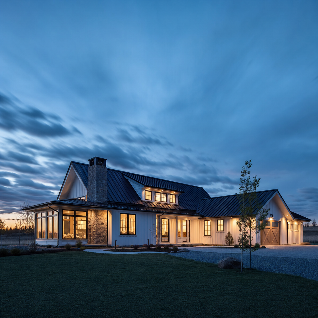
Alberta’s demanding climate and shifting regulatory landscape mandate precise, rigorously detailed attic ventilation in residential roof assemblies. The introduction of the National Building Code - 2023 Alberta Edition (NBC(AE)), effective province-wide as of May 1, 2024, has sharpened both code expectations and plan-review scrutiny for continuous attic ventilation-especially across multifaceted roof geometries that are becoming the regional norm. On the drawing sheet and in construction, continuous, code-compliant airflow must be evident in every valley, dormer sidewall, parapet, and transition. The process extends from initial dimensioning and calculations to product selection, plan review, redlines, and jobsite resolution, drawing from both detailed code sections and hard-learned plan-check and site lessons.
Documenting Alberta Building Code Requirements for Net Free Ventilation Area (NFVA) on Roof Plans and Schedules
Code-Mandated NFVA: Section 9.19.1.2 with Slope-Dependent Ratios
The calculation and explicit documentation of required Net Free Ventilation Area (NFVA) begin at the codebook and must be substantiated on every roof plan, especially for complex assemblies. NBC(AE) Section 9.19.1.2 requires:
- For roofs sloped at 1 in 6 (about 9.5 degrees) or steeper: a minimum unobstructed vent area of 1/300 the insulated ceiling area.
- For roofs sloping less than 1 in 6 or those framed with roof joists (as with some cathedral ceilings): a raised standard of 1/150 the insulated ceiling area.
For a home with a 215 m² insulated ceiling under a steep roof, the required NFVA would be: 215 m² ÷ 300 = 0.72 m² (7,200 cm²). These calculations, broken down by individual roof plane and aggregation, must be tabulated and shown conspicuously on the roof plan-either within a roof ventilation schedule or directly as a call-out adjacent to the relevant roof area. Omission or inaccuracy here is a frequent plan-review redline: "NFVA calculations missing or do not match ceiling area."
The drawing convention at Kingsway Drafting & Design is explicit:
- Roof Plan Legend: "Required attic ventilation per NBC(AE) 9.19.1.2: [X] m² total NFVA (intake/exhaust per detailed schedule)."
- Vent Schedule: List each vent type (soffit, ridge, gable), manufacturer/model, net free area per unit (NFA in cm²), and total number used for each roof segment.
- Dimension Chains and Area Calculations: Where roofs are trapezoidal, L-shaped, or include dormers, include dimension chains to clearly account for each insulated ceiling area "below" each ventilated roof plane. This satisfies code reviewers and avoids disputes over plan accuracy.
Required Vent Distribution: Explicit Top-and-Bottom Placement per 9.19.1.2
The code’s intent for distribution-“vents shall be distributed uniformly on opposing sides, with at least 25% at the top and at least 25% at the bottom”-drives both the strategic layout and the annotation on the plans.
- Plan Sheet Call-Out: "Provide [X] cm² NFA at ridge (top), [Y] cm² NFA at soffit or eave (bottom); balance per code minimums. Vent types and placement per detail A2-04."
- NFVA Table: Show calculations evidencing at least 25% of total NFA at each designated location, with remaining distributed proportionally. Comments like "Top/bottom vent split does not meet 25/25 minimum" are common markups from both City of Calgary and regional Alberta reviewers if assumptions are left unclear or only aggregate values are provided.
Uniformity must be literal; long, unvented runs (such as above a bonus room or isolated ridges) will trigger code review comments: “Ventilation imbalance at NE roof area-revisit soffit/ridge vent placement per 9.19.1.2.”
Roof Joist Spaces and Purlin Interconnection: Specifications per Code
Section 9.19.1.2 also demands: “If each roof joist space is not separately vented, roof joist spaces shall be interconnected by purlins of not less than 38 mm by 38 mm placed on top of the roof joists.” This requirement must be noted on plans and sections wherever floors are framed with continuous joists-otherwise, reviewers often note: "Purlin interconnection note missing; clarify attic venting per 9.19.1.2(4)."
Standard call-out: "Where required, interconnect roof joist spaces via continuous 38x38 mm purlins per NBC(AE) 9.19.1.2(4); reference attic section B4-05."
Detailed Material and Product Standards
Every vent product must meet CAN3-A93-M, “Natural Airflow Ventilators for Buildings” (specification mandated by code). On the schedule, always list the compliance standard and supplier declaration. Drawing specifications also emphasize:
- Vents: Must prevent ingress of rain, snow, and vermin-note mesh size and water-shedding design in section detail.
- Insulation Clearance: Maintain a minimum 63 mm of free space between insulation top and roof sheathing-dimensioned on all roof sections and "cold attic" assembly details.
Sectional and Plan Details for Continuous Airflow at Complex Roof Intersections
Critical Junctions: Valleys, Multi-Pitch Eaves, Dormer Sidewalls, and Parapet Transitions
Complex roofs are commonplace in Alberta infill and high-end custom homes: intersecting hips and valleys, doghouse and shed dormers, parapet transitions. Each junction introduces a potential dead zone for airflow; every one is a hot spot for condensation, mold growth, or code violation if not resolved in detail-not just by general intent. NBC(AE) and the RCABC Roofing Practices Manual both underscore the necessity of preserving positive airflow through such intersections with durable baffles, blocking, and precise dimensioning.
Valleys: Maintaining Uninterrupted Soffit-to-Ridge Flow
The traditional valley-a confluence of two roof planes-presents a tendency for insulation or structure to block the path from eave to ridge. Per code, “baffles must maintain a clear air channel”-a statement that becomes a drawing imperative. Recommended call-outs and details include:
- Section Detail: "Install rigid baffle (min. 25 mm free airspace) spanning from lower edge of insulation to valley apex; maintain 63 mm clearance above batt insulation in valley bay."
- Plan-note: "Extend valley baffles continuous between soffit and ridge vents at all intersecting valleys (ref. Section C2-11 Valley Detail)."
Common redline: “Insulation blocks valley channel at intersecting truss; add continuous baffle and clarify with dimension.”
Multi-Pitch Eaves: Modulating Airflow in Steep/Low Slope Confluences
Where steep and shallow planes meet-especially in quad-levels or roofs with significant pitch transitions-airflow is easily disrupted. The drawing must document:
- Baffle Specification: "At eave transitions, install baffles providing 63 mm clear channel regardless of pitch variance; fix baffles to rafter sides and top plate (ref. Eave Section D1-06)."
- Soffit Vent Note: "Install continuous vented soffit (min. [x] cm²/m NFA) at eave; coordinate vent size to ensure uninterrupted intake across pitch change."
Plan reviewers often call out: “Ventilation path not continuous at multi-pitch eave; detail baffle arrangement through transition.”
Dormer Sidewalls: Enabling Cross-Ventilation and Preventing Trapped Pockets
Sidewall dormers, especially those deep-set on broad attics, can create stagnant dead zones without explicit cross-ventilation. Detailing must provide:
- Dormer Wall Section: "Install sidewall vent (model/spec), align with attic airspace; provide not less than 63 mm clear air channel behind dormer cheek wall; maintain cross-flow between dormer and main attic."
- Plan Symbol: Mark all dormer vents, reference vent schedule, and summarize each bay's cumulative NFA on ventilated side elevation.
Common deficiency: “Dormer side not vented-add vented cheek wall per NBC(AE) 9.19.1.2 and coordinate with main attic line.”
Parapet Wall Transitions: Preventing Moisture at Parapet Bases and Crowns
Where low-slope hip or shed roofs terminate at parapets-a growing feature in contemporary Calgary and Edmonton infill-the precise positioning of low (intake) and high (exhaust) vents is essential. Recommended approach:
- Section Note: "Install parapet base vent (model/spec, NFA per schedule) at least 150 mm above finished roof deck; provide matching exhaust vent at parapet cap; maintain 63 mm ventilation chase behind parapet blocking."
- Coordination Note: "Venting through parapet must use products listed to CAN3-A93-M; integrate with cap flashing per Section F2-08."
Plan review typical: “Parapet detail lacks exhaust vent; revise top and base ventilator positions.”
Material and Installation: Baffles and Blocking
- Baffle Material: Rigid, moisture-resistant material (PVC or corrugated cardboard, 25 mm min thickness); extended above insulation, securely fixed to prevent displacement during insulation installation or wind event.
- Blocking: Non-combustible or treated wood as required by fire blocking code sections; block to the edge of the vent chase but never obstructing the 63 mm minimum air path.
All baffle and blocking details must be dimensioned on section drawings, demonstrating explicit clearances.
Graphic Representation on Drawings to Maintain Clear Ventilation Pathways around Structure, Mechanicals, and Firestopping
Coordinating Attic Ventilation Across Oversized Beams and Structural Members
Large beams, steel purlins, or dimensional changes in truss depth-common in Alberta custom homes-easily disrupt contiguous ventilation chases. The deficiency is frequently spotted in redlines: “Beam at grid F5 obstructs attic airflow; revise detail to maintain 63 mm min. clearance.” It is imperative that drafters:
- Sectional Notation: "Provide trimmed baffle or soffit ventilation chase continuously over/around beam; maintain minimum 63 mm clear above any structural element."
- Dimension Call-Out: Place dimension strings from beam soffit to sheathing and from top of beam to top of insulation in every cross-section through the obstruction.
Where a beam crosses the width of the attic, widespread convention at Kingsway Drafting & Design is to use a "vent chase detail call-out" such as: "See Detail D5-07 for airflow continuation over main beam-63 mm min. airflow maintained using trimmed insulation guards and rigid baffle."
Mechanical Penetrations: Ductwork, Plumbing Stacks, and Attic Pathways
Duct runs or DWV stacks routed through attics require careful choreography. NBC(AE) 9.32.3.11.(8) and related duct sealing standards must be cited if attic ventilation is at risk. Frequent review comments include: “Ductwork interrupts soffit-to-ridge baffle-relocate or reroute to maintain continuous vent.” Solutions include:
- Plan Graphic: Dashed line to indicate mechanical run; call-out: "Duct path below ventilation chase-coordinate with truss layout to avoid vent path obstruction."
- Sectional Detail: "Maintain 63 mm min. vent space beside/over duct; if unachievable, provide alternate vent path (see detail D7-13 for lateral baffle extension)."
- Duct Sealing: Note: "Seal all duct joints with mastic per NBC(AE) 9.32.3.11.(8)-no leakage into vent chase or attic airspace."
Firestopping: Balancing Life Safety and Ventilation
Firestopping can inadvertently block essential airflow if not specifically shown as discontinuous at ventilation runs. A typical plan-check note: “Intumescent firestopping blocks attic vent path at fire separation wall; provide compliant detail maintaining code-mandated air channel.” Mitigation by detail:
- Fire Rated Detail Call-Out: "Install intumescent firestop collar; maintain vent chase continuous with fire barrier to roof sheathing per code; refer to section G2-03."
- Material Schedule: Specify fire-resistant baffle material when vent chase penetrates required fire separations; refer manufacturers with approved listings for such assemblies.
Dimensions, Ratings, and Material Specifications for Clarity and Approval
Every obstruction crossing a vent chase must be explicitly dimensioned-a minimum 63 mm clear airspace remains the gold standard to reference. All drawings require a "VENT CHASE CONTINUITY" note in the general roof/attic keynotes, i.e.: "All vent chases to be kept free and clear of structural, mechanical, and firestopping elements unless alternate, code-compliant venting path is detailed on drawings."
Specifying and Detailing Proprietary Attic Ventilation Products for Complex and Tight Conditions
Code-Mandated Product Performance: Citing CAN3-A93-M and Material Schedules
Not all attic vents, baffles, or intake/exhaust solutions are suitable-or code-acceptable-in Alberta. NBC(AE) requires all venting products to comply with CAN3-A93-M and to be suited to Alberta’s variable conditions (freeze/thaw, snow load, wind-driven rain). Product schedules on the set must include:
- Manufacturer/model (e.g., "Duraflo WeatherPRO 6050 Roof Vent").
- Net Free Area (NFA) per unit-shown in cm² (e.g., "305 cm² per vent, tested to CAN3-A93-M").
- Material spec (e.g., "UV-stabilized polypropylene, rated -40°C to 80°C").
The schedule must tabulate all product types by quantity, NFA, and installation zone-failure here is a common origin for the plan review note: "Vent type/model/NFA not specified; revise product schedule per NBC(AE) 9.19.1.x."
Specialized Vent Types: Low Slope, Tight Bays, and Fire-Exposure Scenarios
- Low-Slope/Flat Roofs: Detail the use of low-profile roof vents with high NFA in line with parapet and ridge transitions; intake locations must be identified on plan and referenced in section. Drawing call-out: "Flat roof vent, model [X], 500 cm² NFA, installed 200 mm clear of parapet base, see Section J1-04."
- “Tight” or Confined Bays: Where standard baffle installs are not possible, proprietary “mini baffle” systems (styrofoam or rigid foam, 25 mm min. thickness, 63 mm air gap) must be called out by product name and placement, with section detail cross-referenced to attic plan. Note: "Install ‘VENTBAY Mini’ baffle in all bays less than 300 mm rafter depth per manufacturer installation literature; continuous vent path to ridge."
- Fire-Exposure Required Vents: Where NBC(AE) Variance 19-BCV-017 is invoked (i.e., near property lines or designated wildland-urban interface), specify: "Intumescent-coated vented soffit, model [X], ULC S135 listed, install per manufacturer listing and city variance approval; see referenced variance documentation."
Section and Flashing Details: Integration with Roofing Envelope
Product specification is incomplete without integration. Section drawings must show:
- Vent/roof interface: Installation height, distance from ridge/eave, integration beneath shingles or membrane, and interface with ice and water shield.
- Flashing: Corrosion-resistant metal flashing (e.g., "26 gauge galv. steel flashing to extend min. 100 mm up vent flange and under adjacent roofing"). Mark flashing lines and lap dimensions on detail.
- Insulation and Vapour Control: At each vent insert (especially proprietary baffle types), show polythene vapour barrier continuity clipped or taped up to baffle for airtightness, but do not obstruct vent chase.
Drawing cross-references between section, product schedule, and roof plan ensure no ambiguity for plan reviewers or site trades.
Strategies for Documenting Drawing Revisions and Resolving Plan-Review or Jobsite Ventilation Deficiencies
Drawing Revision Techniques for Ventilation-Related Comments
Plan-review processes in Alberta are rigorous-reviewers are particularly vigilant for call-outs such as “insufficient NFVA at north eave”, “baffles missing at valley” or simply “vent schedule unclear.” Precise and auditable documentation of each revision is not optional. The established workflow includes:
- Revision Clouds with Delta Markers: Every change responding to a review comment (e.g., added baffles at dormer, increased soffit venting along north eave) is encapsulated in a red revision cloud marked with a delta, tying back to the revision table.
- Comprehensive Revision Table: Each affected sheet includes a table: "Rev 02, 2024-08-14: Revised north eave venting to provide required 0.12 m² NFA as per plan review note, adjusted baffle detail at valley intersection per City of Calgary comments. - JW/RC "
- Transmittal Sheet: Every distribution of revised sheets is accompanied by a transmittal documenting the sheet numbers, revision dates, affected code items, and summary of solutions. This artifact closes the loop with both city reviewers and trades onsite.
Failure to comprehensively flag, describe, and reference all attic ventilation changes frequently leads to delays; plan reviewers often write, “Ventilation revision locations not clear-cloud, annotate, and issuerevision summary.”
Addressing Specific Review and Field Deficiencies
When a plan reviewer cites “insufficient NFVA at north eave,” best practice is to:
- Annotate or table the revised calculation for the exact eave segment: "North eave segment: 11.2 m length × 38 mm continuous soffit vent = 425 cm²/m × 11.2 m = 4,760 cm², plus 2 additional vents at 300 cm² each = total NFA 5,360 cm² (code minimum: 4,725 cm²)."
- Reference directly in the revision bubble: "Increased NFA at north eave to exceed 1/300 ratio; see detail/call-out within revision cloud area ‘A’."
- Revise the vent schedule with delta/Delta-02 notation to indicate all additions or substitutions of vent types, now matching the increased requirement.
For the jobsite deficiency “baffles missing or improperly installed”-often identified during framing or pre-drywall walk-drawings must:
- Detail the required baffle material, spacing, upright orientation, and securement, with enlarged detail keyed as: "Detail E3-09 ‘Baffle Installation at Soffit’ - all bays, 63 mm min. clear to sheathing, attach baffle to rafter at 600 mm o.c."
- Include a general note: "All attic baffles to be inspected prior to insulation; missing/damaged baffles to be replaced per detail E3-09."
Jobsite reports must further reference the sheet, revision number, and detail index-for example, "Ref. A4.2, Rev03, Dtl. E3-09".
RFI (Request for Information) Response Documentation for Continuous Attic Ventilation Issues
RFIs regarding venting details must be managed with traceable, timely written responses and supplementary graphics:
- Formal Written Response: Specify the plan location, code section (e.g., "Response to RFI-017: Ridge vent detail at north gable revised per NBC(AE) 9.19.1.2 and attached sketch SK-114").
- Supplemental Sketches: Attach “SK” drawings, clouded and clearly annotated, showing the precise solution (such as relocated intake vent or extended baffle over unforeseen ductwork obstruction).
- Tracking Register: Log RFI, response date, summary, resolution status, and cross-reference to revised plan sheets in a centralized ‘Issue/Response Register’ accessible to design, review, and field teams.
Ongoing distribution to all parties-owners, builders, city officials, and trades-ensures changes are uniformly implemented and field confusion is minimized.
Conclusion
Elevating drafting practice to meet Alberta’s expectations for continuous attic ventilation-across all roof geometries-demands not only code literacy but also unassailable documentation, graphical clarity, and relentless attention to the interplay between calculation, detail, and field execution. When code sections like NBC(AE) 9.19.1.2, 9.19.1.3, and 9.19.1.4 are not just cited but manifest in every calculation, note, and section, plans move through review faster and buildings endure longer. With methodical attention to baffle and vent scheduling, complex intersection detailing, obstruction coordination, proprietary product integration, and transparent revision management, Alberta’s roof assemblies can be truly ventilated by design, not by accident. Kingsway Drafting & Design embodies this discipline from first sketch to field inspection on every residential project in Calgary and beyond.