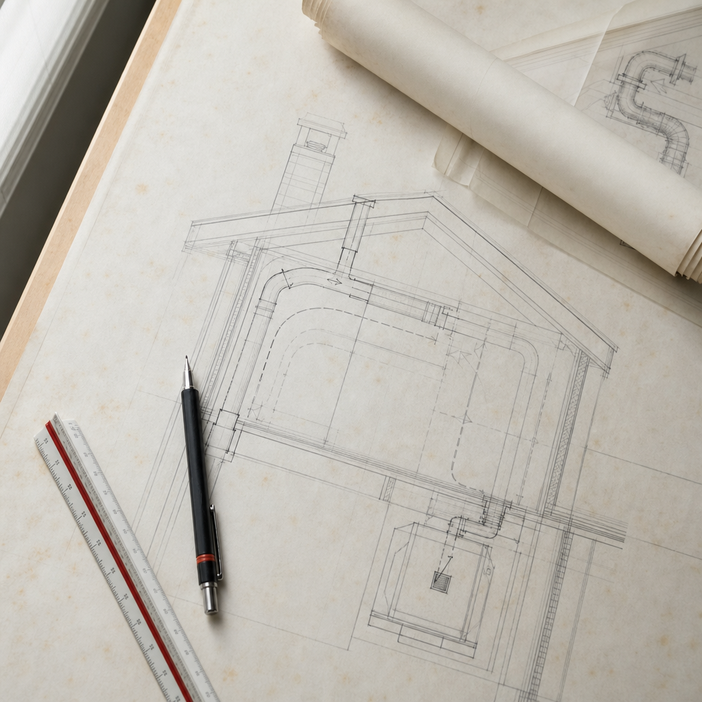
If a fuel-burning appliance in an Alberta home lacks accredited combustion air, it presents not just a code violation but a safety hazard. Section 9.32.3.9 through 9.32.3.11 of the National Building Code - 2023 Alberta Edition (NBC(AE)) prescribe rigorous sizing, detailing, installation, and documentation protocols that must be faithfully executed on working drawings and verified on site. Recent implementations-declared in force May 1, 2024-are highly specific about dimensioning practices, material use, clearance detailing, free area calculations, and the representation of combustion air provisions across mechanical and architectural plan sets. The practical work of the drafter, plan reviewer, builder, or coordinating trades starts and ends with these code-grounded drawing and construction realities.
Sizing, Dimensioning, and Material Specification for Combustion Air Ducts: Sheet Protocols and Free Area Calculations per ABC 9.32.3.9
Duct Sizing Protocols on Mechanical Sheets: Applying Table 9.32.3.9
Mechanical plans for Alberta homes with fuel-fired appliances must display ductwork sized in accordance with the strict benchmarks set in ABC 9.32.3.9. Exhaust and make-up air ducts, as described in this section, are not arbitrarily dimensioned; each drawing must cite the specified minimum diameter, derived directly from the designed fan ventilation rate and duct construction type-smooth or flexible:
- Ventilation Rate ≤ 10 L/s: 75 mm min. diameter (smooth duct) or 100 mm (flexible duct)
- Ventilation Rate ≤ 25 L/s: 100 mm (smooth) / 125 mm (flexible)
- Ventilation Rate ≤ 45 L/s: 125 mm (smooth) / 150 mm (flexible)
- Ventilation Rate ≤ 70 L/s: 150 mm (smooth) / 175 mm (flexible)
Schedules on working drawings must not only record duct diameters but also specify the entirety of ventilation capacity-errors in matching the appliance’s exhaust or make-up air requirements with corrrect duct sizing are among the most persistent plan review redlines noted by Alberta code officials (“Duct sizes must follow Table 9.32.3.9 for specified fan rates”). Every schedule should reference the exact NBC(AE) table for traceability and audit trail.
Free Area Calculations: Annotation and Redline Avoidance
All combustion air intake details must quantify the “free area” provided after accounting for screens, mesh, or louvers. Plan redlines frequently denote: “Insufficient free area for combustion air intake-recalculate.” The mechanical detail must either:
- Provide the arithmetic calculation of open area (e.g., opening size minus screen blockage), or
- Explicitly reference a manufacturer-tested free area, with documentation available on request.
Standard mechanical sheet annotation: “90 mm duct = 6,362 mm² gross area x 60% net free area (after screen) = 3,817 mm²; compliant with ABC 9.32.3.9. and appliance input.” The net free area must satisfy appliance specifications-commonly 1 in² per 1,000 BTU, with a 100 in² minimum-unless otherwise prescribed locally by permit authority.
Material Specifications and Detail Call-Outs: Exhaust, Range Hood, and Ducts in Unheated Spaces
Mechanical sheets must call out precise construction for ducts. ABC 9.32.3.9 mandates:
- Noncombustible, corrosion-resistant ducting for all range hood exhausts (“Duct: 28 Ga. galvanized steel; noncombustible, corrosion-resistant as per 9.32.3.9.(6)”).
- Direct, exclusive routing to exterior; range hood ductwork must lead outdoors, unbranching, with a grease filter at intake-failure to indicate this detail is a common plan review issue.
- Insulation for ducts passing through or within unheated assemblies: always required, min. RSI 0.75 per ABC 9.32.3.9.(5) (“MECH NOTE: INSULATE ALL UNHEATED DUCT RUNS-MIN. RSI 0.75 (R-4.3)”).
- Discharge Specification: “All exhaust and combustion air intake ducts terminate at exterior as shown-see Elev. A4/ME3.1-no intermediate terminations.”
Omit these specifications and the plan will almost certainly be returned with: “Missing insulation detail for duct adjacent to unheated attic-see ABC 9.32.3.9.(5).” Drafters must dimension and tag these precisely, allowing for builder and inspector verification.
Detailing Combustion Air Inlet Terminations on Drawings: Protection, Clearances, and Fire Separation (ABC 9.32.3.10)
Terminations: Weather, Vermin, and Location Detailing
Combustion air openings are not merely symbolic notations-they must be robustly detailed for weather and vermin protection, with strict compliance to ABC 9.32.3.10. Drawing call-outs must explicitly state:
- Hooded termination, min. 6 mm / max. 12 mm screen mesh size, corrosion-resistant (e.g., “Combustion air intake hood: Stainless mesh screen, openings 8 mm, as per 9.32.3.10.(1)(b)”).
- Elevation tags documenting location-e.g., “COMBUSTION AIR INTAKE 300 mm ABOVE FINISHED GRADE, 1.8 m FROM ANY AIR SUPPLY/EXHAUST OUTLET.”
- Details in section showing weatherproof cap and bug screen construction, specified as stainless steel or heavy-gauge aluminum-any deviation is a redline trigger (“Missing screening or incorrect material at intake-provide corrosion-resistant mesh per Section 9.32.3.10”).
Plan reviewers in Alberta routinely comment when protective details are omitted or generic, noting: “Inlet/outlet protection for weather/vermin screening missing-see ABC 9.32.3.10.” Mechanical and architectural sheets alike must carry explicit detail bubbles or notes referencing the code section and section drawing by number.
Clearances: Codified Minimums and Plan Check Common Issues
Code-mandated termination clearances are direct and quantifiable:
- Vertical clearance: 300 mm (1 ft) min. above grade.
- Horizontal separation: At least 1.8 m (6 ft) from any mechanical air-supply inlet, exhaust vent, window, or door.
Drawing conventions demand:
- Plan/data tag on site plan-“COMB. AIR: 1.8 m SEP. TO NEAREST AIR INTAKE/EXHAUST (VERIFY ON SITE)”
- Dimension string on elevation or section-arrowed distances, with notation: “300 mm AFG PER ABC 9.32.3.10(3); 1.8 m SEP. TO WINDOWS/DOORS”
Omission or misplacement becomes an instant plan check issue (“Insufficient clearance-relocate or resubmit details”). Coordination with site grades and adjacent openings is critical at the drafting stage to avoid either site rework or permitting delays.
Fire Separation and Envelope Penetration Details
Penetrations of fire-rated assemblies by combustion air ducts require special annotation per ABC 9.10.9.6:
- “Provide CAN/ULC-S112 listed fire damper at duct penetration-see detail 5/ME6.1.”
- Call-outs on mechanical and architectural sections, keyed back to an explicit UL-rated damper spec in the schedule.
Failure to detail dampers at floor or wall penetrations in multi-family or attached dwellings is among the most frequent and costly review comments in Alberta city jurisdictions. Each fire separation breach must be detailed, and cross-referenced in both the mechanical schedule and wall assembly keynotes, with the relevant code clause annotated for traceability.
Integrating Combustion Air Supply for Multiple Appliances and Equipment Rooms: Shared Air Requirement Detailing and Impact of Building Air-Tightness (ABC 9.32.3.11)
Shared Equipment Room Air: Sizing Methodology and Duct Coordination
Large Alberta homes or multi-unit dwellings often employ shared utility or mechanical rooms with multiple fuel-burning appliances. ABC 9.32.3.11 sets out demands for duct sealing, size, routing, and performance-a complex coordination exercise between plan, section, and isometric views. All joint locations in combustion air ductwork must be sealed with mastic, UL 181 foil tape, or a manufacturer-certified sealant-sheet notes must state: “Seal all combustion air duct joints (mastic) per 9.32.3.11.(8).”
The required combustion air flow for a shared mechanical room is based on the aggregate BTU input for all appliances-ducts are then sized to provide the manufacturer’s specified net airflow (typically 1 in² per 1,000 BTU/h min.). Plans must:
- Tabulate appliance BTU input on mechanical schedules.
- Directly show combustion air duct size and free area provision based on this calculation.
- Include duct length, number of bends, and routing parameters as per Table 9.32.3.11.-A (e.g., “90 mm dia. max. 3 bends, total 5.2 m length per Table A”).
Redlines at this stage are typically: “Provide calculations demonstrating adequate combustion air supply for all appliances in the shared mechanical room,” and “Clarify duct sizes and lengths to comply with Table 9.32.3.11.-A.” Diagrams often incorporate a ducting schedule listing each appliance, required air, and the corresponding duct sizing, with routing depicted in both plan and riser diagram formats for cross-checking and on-site coordination.
Building Air-Tightness: Drawing Implications and Code Notes
Demands for Alberta home envelope air-tightness are intensifying, presenting new drafting challenges. Tight homes increase the risk of depressurization-thus, mechanical sheets should include:
- Explicit notes on air/vapour barrier coordination at intake penetrations: “COMBUSTION AIR INTAKE PENETRATION: SEAL TO AIR/VAPOUR BARRIER-SEE ENVELOPE DETAILS.”
- Mechanical schedules identifying risk of negative pressure; for direct-vent or sealed-combustion units, “NO ADDITIONAL ROOM COMBUSTION AIR REQUIRED PER STANDATA 19-BCI-012-G-01-20-B149-1.”
- Fireplace supply annotation: “Combustion air supply independent from corridor; pressurized corridor system prohibited-per City of Calgary RB06-030.”
Failure to integrate air-barrier and mechanical penetrations fosters disputes, field RFI, and costly change orders during air testing or occupancy permit review.
Material Specification: Duct Sealing, Length, and Free Area on Drawings
Combustion air ducting in shared spaces must comply with:
- Galvanized steel or SMACNA-standard metallic ducts (“Combustion air ductwork: Galv. steel, 28 Ga. min., per Table 9.32.3.11.-A”).
- UL 181-rated mastic or foil tape sealing at all joints (“All duct joints sealed (UL 181) per 9.32.3.11.(8).”).
- Velocity control: duct sizing to achieve 500-700 fpm airflow, balancing code minimum area with sound/pressure drop considerations.
Combined, these must appear in annotated detail, mechanical schedule, and specification block, with reference to ABC 9.32.3.11 and the applicable STANDATA and City regulation bulletins as context for plan reviewers.
Annotation Standards, Code Referencing, and Preempting Redlines for Combustion Air: From Mechanical Schedules to Plan-Set Details
Code Referencing and Sheet Note Practices
Each aspect of combustion air documentation must point directly to the governing Alberta code section. NBC(AE) 9.32.3.8 and 6.2.3.8 are most cited, requiring mechanical ventilation to prevent negative pressure affecting appliance operation. On the sheet, best-practice annotation is:
- “Provide combustion air intake per NBC(AE) 9.32.3.8 and 9.32.3.9. Sizing as per Table 9.32.3.9; termination per 9.32.3.10.”
- Reference to GUIDE or STANDATA number where local amendment applies (“See Alberta STANDATA 06-BCI-032 for further detail”).
- Mechanical schedule footnotes cross-referencing section views or detail bubbles for clarity (“For intake termination construction, see Detail 7/ME4.1; for fire separation, see 3/AR5.2”).
Avoiding redlines requires all annotations to tie back to precisely cited code text and coordinated sheet references, reducing ambiguity at permit or inspection.
Mechanical Schedule Detailing: Free Area, Material, Termination
In mechanical schedules, list each combustion air size and associated free area calculation-never leave such fields as “TBD” or “see HVAC vendor” as this reliably triggers permit office redlines. Example line item for a high-efficiency furnace and water heater sharing a 150,000 BTU/h supply:
- Combustion Air Intake: 200 mm diameter (31,416 mm² gross, 18,849 mm² free area after mesh), per ABC-Table 9.32.3.9, Schedule Line #M-101.
- Termination Detail: “Exterior wall, 1.8 m from window/door, 300 mm above grade. Hooded with stainless mesh, 8 mm aperture.”
- Material: “28 Ga. galvanized steel duct, joints sealed (UL181), insulated (RSI 0.75), per ABC 9.32.3.9/9.32.3.11.”
Plan review redlines such as “Missing termination details for combustion air ducts” are preempted by such comprehensive scheduling and explicit reference.
Detail Drawing Conventions and Typical Redline Triggers
Combustion air intake/exhaust details should always be drawn at not less than 1:10 scale for clarity, including:
- Screen/context bubble showing hood, mesh, insulation wrap, and connection to air/vapour barrier-tagged dimensions for each component and material call-out by code specification (“8 mm SS mesh, RSI 0.75 min. insulation”).
- Section location tags on plan referencing the relevant detail drawing (“See 14/ME5.1 for intake assembly”).
- A note box referencing code: “DETAIL COMPLIES WITH ABC 9.32.3.10; CLEARANCE REQ’D AS DIMENSIONED.”
Redlines such as “Insufficient details-missing call-outs for screen type, mesh size, insulation, and clearances” are directly avoided by these best-practice conventions. The goal is no ambiguity for builder, inspector, or plan reviewer; every dimension, material, and code clause is visually and textually referenced.
Jobsite Coordination, Drawing Integrity, and Installation Challenges for Combustion Air Ductwork
Field Installation Realities and Duct Routing Dilemmas
Construction-phase execution of combustion air ducts in Alberta is only as robust as the drawing’s clarity and depth. The NBC(AE) stipulates rigid duct material and minimum clearance standards that must be both specified and respected in the field:
- Material: Galvanized steel, 28 Ga. minimum, noncombustible, corrosion-resistant.
- Minimum cross-section: 3” (76 mm) unless a larger diameter is shown for capacity or free area compliance.
Real-world routing requires mechanical, structural, and architectural coordination, especially where physical site conditions or trades’ routing conflicts arise. Typical call-outs and installation notes:
- “Combustion air duct to remain uncompressed and unobstructed throughout-no sharing with other systems.”
- “Clearances to combustibles as per code and Kingsway detail 02/ME5.1-see chart.”
Clearances to Combustibles: Codified in Section and Table, Noted on Sheets
The complexity of maintaining proper clearances is illustrated by the ABC-derived “plenum clearance” tables:
- Within 450 mm of plenum ≤75 mm clearance: Duct clearance equals plenum clearance.
- Beyond first 450 mm: 12 mm min. clearance; zero permitted with post-bend shielding.
- For plenum clearance 75-150 mm: Within 1,800 mm, match plenum; beyond, 12 mm or zero with bend.
- For plenum clearance >150 mm: 1,000 mm at plenum distance; 150 mm up to 1,800 mm out; 25 mm or 8 mm past bends.
Plan sets must incorporate section views at all major transitions, with tag notes: “See Table-Clearances for Combustion Air Duct Adjacent to Plenum (ref. ABC, Kingswaybuilders.ca).” Omission results in repeated field queries and inspection fails.
Fire and Envelope Penetrations: Annotated Details and Trade Coordination
Every penetration-fire-rated or exterior envelope-demands annotated detail:
- Fire separation (multi-unit): “Provide CAN/ULC-S112 damper at penetration; see Detail 9/ME5.2.”
- Envelope seal: “Maintain continuity of air/vapour barrier at all combustion air penetrations-seal per Envelope Detail 15/A4.1.”
Site challenges such as ducting through tight joist bays or clashing speeds with electrical/plumbing often force reroutes-making full as-built coordination, BIM clash detection, and pre-construction walkthroughs necessary. Each field change must preserve clearances, insulation, and material integrity depicted on original plans; otherwise, plan amendments and possible reinspection cycles follow.
Trade Coordination and Installer Guidance: Field-Facing Drawing Notes
To minimize built-in errors, all construction drawings should offer explicit, trade-facing notes including:
- “Review combustion air routing with HVAC and framing trades prior to rough-in-report conflicts to design team.”
- “No reduction in duct size or alteration to routing permitted without re-approval-maintain free area and insulation at all times.”
- “Sealant at all penetrations to match adjacent air/vapour barrier; verify compliance at air sealing inspection prior to covering.”
Failure in coordination and field clarification is the root of most on-site combustion air compliance issues in Alberta. Early, explicit drawing notes and review sessions, especially when using BIM for clash detection, can eliminate retrofits and prevent safety, schedule, and legal setbacks.
Conclusion
Drafting code-compliant combustion air provisions for Alberta homes goes far beyond generic schematic representation-it demands quantifiable duct sizing, explicit specification of all duct, hood, and screen materials, diligent dimensioning of inlet and outlet terminations, detailed air-barrier and clearance coordination, unambiguous scheduling with reference to current ABC sections, and robust, code-anchored detail drawings anticipating both plan review and jobsite challenges. When these standards are faithfully rendered and maintained from first submission to final inspection, Alberta homes achieve the safety, efficiency, and durability demanded by the latest building codes and municipal enforcement. Kingsway Drafting & Design’s attention to every combustion air detail ensures Alberta residential projects stay code-compliant and builder-friendly, all the way from drawing to occupancy.