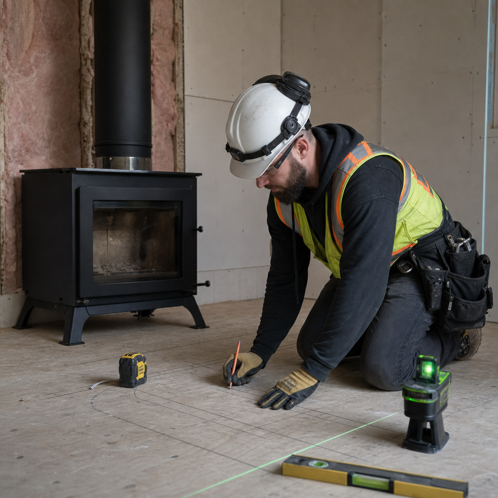
Factory-built fireplaces and wood stoves in Alberta homes are governed by exacting clearance and materials requirements defined by NBC(AE) Part 9.22, relevant ULC/CSA listings, and installation code CSA B365/B415.1. Compliance begins with the drafter: code-compliant clearances, detailed callouts, and meticulous annotation strategies must appear consistently across plans, sections, details, and schedules. When dimensioning these systems, omissions and ambiguities can trigger not only plan-review redlines but costly delays and field corrections. Each aspect of the appliance-to-building interface, from hearth projection to chimney firestopping, is a locus for code enforcement and calls for rigorous documentation.
Dimensioning and Annotation Standards for Factory-Built Fireplace Clearances
ULC-S600 Series Listings, Zero-Clearance, and Manufacturer Requirements
The term "zero-clearance fireplace," widely used in Alberta, refers to factory-built fireplaces listed to CAN/ULC-S610 and installed per manufacturer specifications. Section 9.22.8.1. of NBC(AE) 2023 mandates adherence to these standards. However, "zero-clearance" is a misnomer. In every permitted installation-and on every drawing-the manufacturer's minimum clearances to combustibles must be shown and specified without ambiguity:
- Clearance to Combustible Framing: 100 mm (4") minimum between the fireplace’s back and sides and adjacent combustible framing, except as follows: If in an exterior wall, the minimum is 50 mm (2") (NBC(AE) 9.22.9.3.).
- Clearance to Fireplace Opening: Combustibles are prohibited within 150 mm (6") of the opening. Where a combustible projects more than 38 mm (1.5") from the face above the opening, the required clearance above extends to 300 mm (12") (NBC(AE) 9.22.9.3.).
Plan reviewers and field inspectors consistently require drawings to reference both ABC and manufacturer’s instructions. One frequently cited comment: “Provide manufacturer’s installation manual to verify clearances and installation requirements.” Incorporating these references is more than pro forma-it is vital detail for construction and inspection.
Integration of NBC(AE) 9.22 Code Requirements into Plans, Sections, and Details
Precise integration of code-mandated clearances requires consistency across plans, sections, elevations, and construction details:
- Dimension strings must run clearly between fireplace face and combustible face-typically from firebox or surround finish to nearest framing member (stud, trimmer, header).
- Every section must note the minimum 100 mm/50 mm clearance requirement as it applies to both vertical and lateral conditions, especially at reveals, bulkheads, or chase surrounds.
- Schedule and annotate hearth extension per NBC(AE) 9.22.5.2.: Minimum 400 mm (16") in front and 200 mm (8") to either side for openings under 0.56 m²; 500 mm (20") front and 300 mm (12") sides for larger openings.
Typical plan review redlines regarding ambiguous or missing dimensioning include: “Unspecified clearances to combustible members”, “Dimension strings unclear-define distance from fireplace wall to stud face”, and “Omit reference to ‘zero clearance’ unless verified by installation manual.”
Drawing Call-Outs for Framing Interfaces and Combustible Setback Detailing
The detail conventions on architectural drawing sheets for fireplace clearances must address:
- Studs, Headers, Trimmers: Use dimension strings and callouts such as “Provide min. 100mm clearance between fireplace shell and combustible framing, per NBC(AE) 9.22.9.3. and ULC-S610 installation guide.”
- Mantels: Annotate “Min. clearance between top of fireplace opening and lower face of combustible mantel: 300 mm (if the mantel projects more than 38 mm from fireplace face) per NBC(AE) 9.22.9.3.”
- Hearth Extensions: Plan and section call-outs must read “Hearth extension to comply with NBC(AE) 9.22.5.2.: min. 400 mm (16") in front and 200 mm (8") past each side of firebox opening.” Adjust dimension strings for larger fire openings as per code.
Redline Triggers for Dimension Strings and Framing Interface Details
During plan review, redlines frequently occur around:
- Unspecified or missing clearances between appliance and framing.
- Dimension strings not tied directly to building grid or core framing layout, leading to confusion for framers and inspectors on site.
- Omission of installation manual references-almost always required when fireplace models are “zero clearance.”
Sample code inspector comment: “Clarify dimension from unit to face of adjacent stud-100 mm min. required, cannot assume factory-clearance unless stated in listed data.”
Material Specifications, Ratings, and Detail Conventions
Factory-built fireplaces must also be referenced to:
- Fireplace Wall Thickness: Minimum 190 mm including any liner if liner is less than 51 mm (2") thick (NBC(AE) 9.22.2.1.a.).
- Hearth Support: Hearths must be constructed on reinforced concrete slab not less than 100 mm (4") thick at supports (min. 50 mm at unsupported edge) (NBC(AE) 9.22.5.3.).
- Non-Combustibility: All hearth and surround materials must be clearly called out as non-combustible, and fire-resistance rating referenced if required by room/separation context. Use tags such as “12mm cement board (non-combustible) continuous under all finished flooring within hearth zone”.
Detailing these aspects at the drawing stage ensures no ambiguity arises on site or in permit review. Always reference the particular listing standard and manufacturer's installation guides within the general notes and within key detail callouts.
Drafting Exploded Section Details for Solid Fuel-Burning Appliance Protection (Wood Stoves)
Code Basis: ABC 9.22, CSA B365/B415.1, and Clearance Reduction Strategies
Wood stoves are governed by NBC(AE) 9.22.10 and must be installed per CSA B365, “Installation Code for Solid-Fuel-Burning Appliances and Equipment.” Drafted details must explicitly depict both standard and reduced clearances-if any part of the structure (walls, floors, ceilings) is combustible.
- Default Clearance (per manufacturer and CSA B365): Standard labeled clearance is typically 450 mm (18") from stove sides/rear to combustibles, unless reduced by certified heat shielding per CSA B365 Table 2.
- Heat Shielding for Reduced Clearances: Ventilated metal heat shields (24 ga. steel or thicker), set on 21 mm (7/8") non-combustible spacers off the wall and open at top/bottom to allow airflow, may allow clearance reduction to as little as 150 mm (6")-only if certified in appliance listing/install manual (CSA B365 Table 2).
Material Specifications for Clearance Reduction: Details and Fastening
Every detail sheet or enlarged section must spell out all protection scheme layers. A typical exploded section for a wall shield behind a wood stove includes:
- Heat Shield: 24-gauge galvanized sheet steel or 12 mm (1/2") cement board, sized to extend at least 450 mm (18") beyond the appliance limits in every direction where reduced clearance is claimed.
- Air Gap: Continuous 21 mm (7/8") non-combustible spacers at corners and mid-span (non-combustible ceramic or metal), maintaining an unobstructed air space for convective cooling.
- Ventilation: Call for open gap (min. 25 mm/1") at both top and bottom of shield to permit airflow.
- Fastening: Non-combustible screws through shield/spacer into wall structure. Standard detail callout: “Fasten shield with min. #8 x 38mm (1.5") non-combustible screws at 400 mm oc through spacers into framing; edge/field, min. 50 mm from shield edge.”
Code Note: “Install heat shield and spacers per CSA B365 Table 2 for clearance reduction; provide manufacturer’s data if further reduction is claimed.”
Common plan redline-“Missing air gap detail and fastening schedule for heat shield; resubmit detail with dimensions and spacing per CSA B365.”
Hearth Extension Detailing: Section Calls and Drawing Standards
All appliances must be shown with code-compliant hearth extension. NBC(AE) 9.22.5.2./CSA B365 references:
- Thickness: Minimum 50 mm (2") thickness, non-combustible.
- Plan/Section Dimensions: 400 mm (16") projection in front of appliance door, 200 mm (8") past each side. (For appliances with doors exceeding 0.56 m²: 500 mm/20" front, 300 mm/12" side.)
- Material Specification: Annotate as “100 mm reinforced concrete hearth slab on non-combustible support; finished with 12 mm raised edge continuous.”
- Exploded Section Detail Layers: Show subfloor, fire-resistive hearth panels (with edge dimensions), finish, and required lap/overlap of shielding at appliance interface.
Full compliance requires call-outs such as:
- “Extend non-combustible hearth 400 mm min. forward of door and 200 mm beyond each firebox side-see NBC(AE) 9.22.5.2. & CSA B365.”
- “Provide 50 mm clearance between non-combustible hearth and adjacent combustible flooring-insulate edge with mineral wool.”
Redlines: Frequently Overlooked in Detailed Sections
Recurrent review comments and on-site audit findings include:
- Omission of wall/floor air gap dimensioning, or neglecting to call out non-combustible spacers specifically.
- Missing fastener schedule or incorrect specification (“drywall screws” instead of “#8 non-combustible” for shield installation).
- Ambiguity in hearth extension thickness on section view; e.g. plan shows adequate dimension, but section omits slab thickness or composition.
- Shield or hearth not shown to edge of protection zone; reviewer note: “Stove shield must exceed appliance outline minimum 450 mm each side.”
Section details must explicitly define where shield overlaps with hearth, how air is ventilated, and specify that all visible materials are certified non-combustible.
Coordinating Chimney and Vent System Clearances Across Plan Sets
Applicability of Chimney and Venting Standards: A/B/L/BH Vents
Chimney and vent system penetrations-across floors, walls, and roofs-require dimensioned details for clearances, firestopping, and adjacent framing. NBC(AE) 9.21 and 9.22 specify:
- Masonry/Concrete Chimney Clearances (NBC(AE) 9.21.5.1.): 50 mm to interior chimneys, 12 mm to exterior chimneys; 150 mm to cleanout openings; 12 mm to combustible flooring.
- Type A, B, L, BH Venting (per appliance listing): Refer to listed manufacturer's clearances or CAN/ULC-S629 as applicable. Alberta expects the greater of the two values where both are given.
Detailing Penetrations: Floor, Ceiling, and Roof
Architectural plan sets must coordinate:
- Floor Plan: Show planned appliance and vent penetrations, dimensioned off grids and partition faces with call-outs such as “See Detail 3/A501 for typical vent floor penetration framing and firestopping.”
- Floor Framing Plan: Mark double-joist headers/trimmers where vent openings interrupt joist continuity. Note “Opening framed per NBC(AE) 9.23.5.2.; maintain min. 50 mm clearance between vent and any wood framing.”
- Section/Elevation: Enlarged details at each penetration (floor, ceiling, roof)-dimension the clearance ellipse, thickness of firestopping, and path of vent relative to all combustibles.
- Roof Plan: Show vent projection, flashing, and call out the minimum vertical and horizontal clearance zones at penetration, with note: “Install firestopping/fire-block around all combustible penetrations per NBC(AE) 9.10.16.3.”
Typical issues in plan review: missing call-outs for additional blockings, omission of firestopping at interstitial floor and ceiling levels, ambiguous vent clearance symbols not cross-referenced to details. Reviewer comment: “Show detail at all vent/fireplace penetrations indicating firestopping and min. clearance to joists, per manufacturer and NBC(AE) 9.21.5.1.”
Cross-Referencing and Coordination for Field Interpretation
Cross-reference every plan view symbol to a detail or section: e.g. if a B-vent passes through the second floor and attic, floor and roof plans each carry a circle symbol with “V-1,” cross-referenced in the door/window/appliance schedule and keyed to Detail 5/A601 (vertical section at vent stack).
In every detail, call out:
- Framing modifications-headers, trimmers, blocking.
- Exact minimum clearance circle (50 mm from masonry, per code or greater if per manufacturer’s spec).
- Firestop material (e.g. “Mineral wool fireblock, thickness per detail, min. 100 mm deep, compressed tight to vent at every floor and ceiling penetration, NBC(AE) 9.10.16.3.”).
This explicit coordination enables framers, HVAC contractors, and inspectors to interpret the intended construction sequence without recourse to assumptions or conflicting detail sheets.
Strategic Annotation and Layering for Fireplace and Wood Stove Systems on Plan Sets
General and Code Reference Notes for Permit and Construction
Plan sets must include:
- General Notes: “All fireplaces and appliances shall be certified to CAN/ULC-S610 or equivalent; installed as per listing and manufacturer’s instructions and NBC(AE) 9.22 unless noted otherwise.”
- Code Notes: “Maintain all clearances to combustible materials as per NBC(AE) 9.22.9.3 and install hearths/combustion air to requirements of NBC(AE) 9.22.1.4.”
- Keyed Notes/Index: Each system-appliance, vent, hearth, firestop, clearance shield-assigned a symbol and full description for quick field confirmation.
Systematic Layering of Appliance-Related Elements
- Clearance Zones: Dedicated CAD layer (“A_FPL_CLEAR”) using dashed lines at the actual dimensioned clearance from appliance face to combustibles. No dimension ambiguity-layers printed in colour for plan review; black/white on construction sets. Label: “Clearance zone, do not install combustibles inside shaded area (see NBC(AE) 9.22.9.3./manufacturer’s listing).”
- Firestopping: Separate layer (“A_FIRESTOP”), cross-hatched or shaded, clearly denoting required fire-blocking/fill at all vertical and horizontal penetrations. Call-out includes: “Provide firestopping at all levels, per NBC(AE) 9.10.16.3.”
- Structural Framing: Show all required supplementary framing for hearth loading, vent openings, and chase supports. Layer “S_FPL_SUPP”-notes such as “Provide double header/trimmer at opening, size as per structural notes; coordinate with vent path.”
Revision tracking: If clearances must be revised after plan check, only the affected layers update, minimizing error propagation across the set.
Standard Annotation and Plan Sheet Conventions
- Plan View: Schematic appliance envelope, required clearance envelope (dashed), hearth outline (solid). Keynote bubbles identified per schedule.
- Elevations: Show mantel/shelf/projection clearances vertically from firebox opening, with height and projection notes.
- Sections and Details: Enlarged detail at each interface-firebox to stud, vent/trimmer intersection, hearth conditioning (support, edge detail). All materials, thicknesses, and ratings fully labeled.
Permit Review: Typical Comments Demanding Improved Annotation
- “Clarify which wall finish is non-combustible at clearances zone-specify make/thickness.”
- “Keynote applied to incorrect vent type-specify B-vent or L-vent as per appliance.”
- “Note missing for combustion air supply (NBC(AE) 9.22.1.4)-add general note for outdoor air intake location, diameter, and termination.”
Success at permit and during construction hinges on both depth of annotation and rigorous consistency across plan set layers and sheets.
Addressing Common Plan Review Redlines and Jobsite Non-Compliances for Combustible Clearances
Errors in Drafting: Hearths, Air Gaps, Appliance Clearances, Firestopping
- Incorrect Hearth Dimensions: The most frequent error is undersizing the hearth-e.g., dimensioned at 350 mm front, 100 mm side. Reviewer comments: “Hearth extension dimensions are insufficient; please revise to meet minimum requirements as per ABC Section 9.22.5.2.”
- Missing Air Gap Details: Floor and section drawings failing to show 50 mm (2") chimney-to-framing gap for interior stacks, or 12 mm (1/2") for exterior chimneys. Found by plan reviewer, then flagged again at framing inspection.
- Insufficient Appliance-to-Wall Clearances: Plans/specs omitting explicit dimension from appliance shell to combustible wall-especially common when wood stove or fireplace is located in bay/bump-out. Plan review calls: “Specify clearances between the appliance and combustible walls in accordance with ABC Section 9.22.9.3.”
- Inadequate Firestopping Call-Outs: Section and plan miss required sealing/fill at chimney or vent chase penetrations. Comment: “Include firestopping details for all penetrations through fire-rated assemblies as required by ABC Section 9.10.9.6.”
Corrective Drawing Actions and Standardized Detail Conventions
- Revise all hearth outlines to meet minimum 400 mm (16") front, 200 mm (8") side extensions for standard doors. Larger doors per ABC as above, with thickness and material specification called out: “Hearth extension, 50 mm thick, non-combustible (concrete/stone), continuous”.
- Revise all sections showing chimney/wall interfaces to include continuous dimension string at code air gap-annotate: “Provide 50 mm clearance between chimney and combustible framing at all interior stacks (ABC 9.21.5.1.), 12 mm at exterior.”
- Add explicit dimension and note at every appliance location: “Maintain 100 mm clearance (50 mm at exterior wall) between back/sides of appliance and combustibles (ABC 9.22.9.3.)”.
- Supplement all ceiling/floor/roof penetrations with detail keyed call-out: “Seal all penetrations through fire-rated assemblies with approved firestopping (mineral wool or intumescent), per ABC 9.10.9.6.”
Reference each code section “in line” on call-outs and detail schedule to ensure reviewer cannot mistake or overlook compliance. Mark up field-directed sketches with clouded revisions as required by local authorities.
Implications of Incorrect Field Installations
Failure to observe these drafting and coordination best practices yields:
- Immediate Life Safety Hazards: Reduced or missing clearances allow heat to transfer to combustibles; risk of hidden ignition is greatest near flue, mantels, and hearth junctions.
- Field Non-Conformance: Installers may default to least clearance if plans are silent; repeated inspection failures for non-compliance; potential for forced backtracking (removal of finished work, delays).
- Insurance Liability and Cost: In the event of fire-even if unrelated-deviations from approved plans with correct clearances become liability issues for owners, builders, and designers alike.
- Structural/Moisture Damage: Inadequate firestopping around chimneys and vents increases the spread of both fire and smoke, and may enable water/moisture ingress at roof/wall interfaces.
Recommended Drawing-Sheet Conventions for Correction
- Every dimension string must start at core appliance shell and terminate at “face of nearest combustible.”
- Hearth, clearance shield, and firestop details receive unique detail keys and reference back to general notes for materials/rating.
- Include schedule with make/model/ULC/CSA listing for each appliance, with instruction: “Contractor shall provide current manufacturer’s installation instructions on site at all times. All installations to comply with latest edition thereof.”
Key Material and Spec Dimensions Review
- Hearth: Non-combustible, 50 mm minimum thickness, dimensioned as per code based on opening size (16"/8" or 20"/12" rule).
- Chimney Air Gaps: 50 mm (interior), 12 mm (exterior) per ABC 9.21.5.1.
- Appliance Clearances: 100 mm (4") side/back default; 50 mm (2") at exterior wall; 150 mm (6") opening; 300 mm (12") mantel if projection exceeds 38 mm.
- Firestopping: Continuous, non-combustible material tested to required assembly rating at all penetrations.
References and Compliance Resources
- National Building Code - 2023 Alberta Edition
- Alberta Building Codes and Standards
- Canadian Chimney: Fireplace and Chimney Code Reference
- Wood Heat Organization - Installation Clearances
- City of Leduc - Factory Built Fireplaces and Wood Burning Stoves
Rigorous, code-referenced drafting and detailing ensure that every fireplace or wood stove project designed by Kingsway Drafting & Design delivers both safety and full regulatory compliance for Alberta homes.