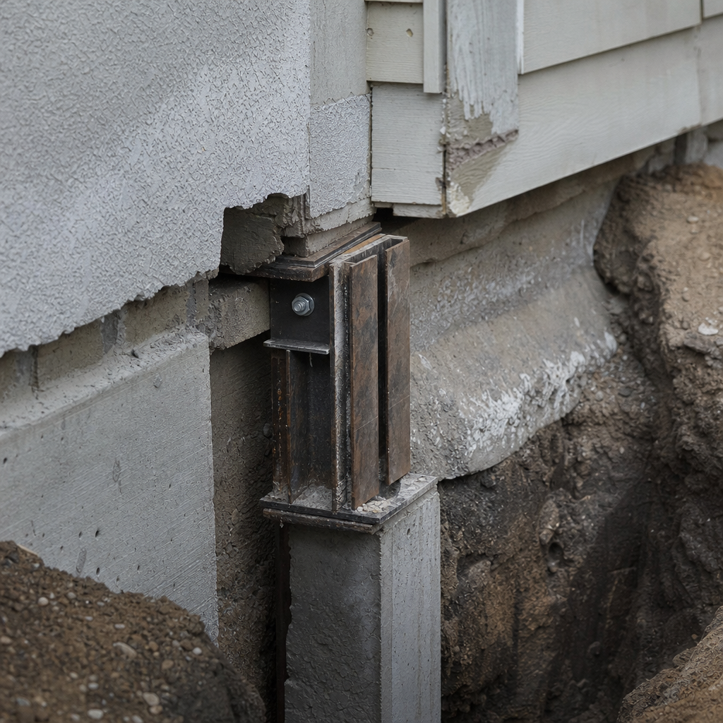
Foundation underpinning for Alberta residential projects demands rigorous attention to code-referenced drawing conventions, granular sequencing details, full-scope reinforcement schedules, municipality-driven permit documentation, and prescriptive jobsite instruction. Navigating Alberta’s regulatory architecture-anchored by the Alberta Building Code (ABC) and CSA concrete standards-translates directly to the clarity and approval of architectural drawing sets, plan review outcomes, and field execution. Direct integration of dimensional data, code section call-outs, and explicit procedural notes ensures the work stands up to scrutiny from plan reviewers, structural engineers, and construction crews alike.
Integrating Alberta Building Code & CSA Concrete Standards on Underpinning Detail Sheets
Direct Referencing of ABC Sections and CSA A23.1/A23.2 in Drawings and Notes
Detail sheets for residential underpinning must do more than depict geometry; they must explicitly situate new work within the legal and structural frameworks outlined in the Alberta Building Code and relevant concrete standards. This starts by embedding the exact code provisions governing frost depth, lateral support, soil bearing, and concrete quality directly in general notes and keyed detail call-outs.
- Frost Depth Requirement: ABC 2019 Section 9.12.2.2 mandates that all new foundation elements, including underpinning, must extend a minimum of 1.2 meters below finished grade in most of Southern Alberta to mitigate frost heave. This should appear on every underpinned footing and wall detail, e.g.:
“Footing depth below grade: min. 1.2m as per ABC 2019 9.12.2.2” - Lateral Support: ABC Section 9.15.4.2 governs the requirement for lateral support to both the top and bottom of foundation walls, crucial anytime excavation, underpinning, or modification destabilizes an existing structure. In underpinned wall sections, notation must read:
“Foundation wall to be laterally supported per ABC 2019 9.15.4.2 (see shoring/phased sequence details)” - Soil Bearing Capacity: For footings, ABC 9.15.3.4 and associated tables define minimum widths and required investigations based on assumed bearing capacities. In the general notes:
“New underpinning footings sized to ABC Table 9.15.3.4, min. width per soil bearing capacity (geotechnical report ref. 22-106).”
CSA Concrete Standard Call-Outs
Material and testing standards for concrete are covered by CSA A23.1 (“Concrete materials and methods of concrete construction”) and CSA A23.2 (“Methods of test and standard practices for concrete”). Integration in both ‘General Notes’ and on specific detail bubbles is critical:
- Material Spec:
“All concrete work for underpinning per CSA A23.1-19 and CSA A23.2-19, min. 25 MPa @ 28 days, 5-8% air entrained.” - Testing: Placement notes must specify test method execution:
“Slump, air content, and compressive strength tests per CSA A23.2 (site cylinders: 3 per pour min.)”
Detailing, Dimensions, Material Ratings, and Drawing-Sheet Conventions
- Footing Width/Depth: Show on every section and plan:
“Underpinning concrete min. 500mm wide x 400mm deep (ABC T9.15.3.4 & structural dwgs)” - Compressive Strength:
“CONCRETE: 25 MPa @ 28 days (CSA A23.1-19)” - Reinforcement: Reference both ABC and CSA codes, bar sizes, spacings, and cover:
“15M bars @ 200mm o/c (each way), min. 50mm cover, epoxy-coated if in contact w/ soil, per CSA A23.1-19” - Revision Blocks: Any additions or removals must be tracked:
“Rev. 3 - Underpinning sequence and pit detail call-outs revised to meet ABC 9.12.3.2, see plan reviewer note 4, 2024-03-22.”
Plan Review Redlines: Code Reference Issues
- Missing or Misapplied Code Sections: “Reference to frost protection insufficient; foundation must be continuous to 1.2m min. below grade (ABC 9.12.2.2).”
- Insufficient Material Specification: “Specify concrete class, compressive strength, and air entrainment per CSA A23.1.”
- Non-Conforming Detail Conventions: “Provide explicit bar mark/tag in schedule; general note insufficient for field verification.”
Full compliance and ease of reviewer approval hinge on carrying these references-not only in drawing general notes but keyed directly to every pertinent detail, section, and schedule so there is no ambiguity regarding compliance or construction expectation.
Granular Drawing Mechanics for Underpinning Pit Sequences: Plans, Sections, and Graphic Conventions
Exploded Isometric, Plan, and Sectional Sequencing
The ‘pit and skip’ method (or staged underpinning) for existing foundations is a staple in safe, code-compliant foundation modification and must be visually described in detail on the drawing set. Exploded isometric views demonstrate the phased relationship between new underpinning sections and the existing structure, clarifying protection zones and sequence for contractor implementation and inspector review.
- Isometric Detail Reference:
“Detail 2/SE4: Exploded isometric showing new underpinning pit (hatched) beneath existing wall (solid), sequence #1 per plan.” - Plan View Dimensioning: Explicit grid lines identify pit length, skip sequence, and re-occupation of pits:
“Underpinning pits excavated 1.2m long, leaving 2.4m between adjoining (skip length = 2x pit), see 1/A5.” - Section Cuts:
“Section B-B (Sheet A5): Underpinning pit showing existing strip footing, new mass concrete (M20), gap at underside for dry pack. Dry pack 1:3 sand-cement mortar, placed 24-48 hrs after concrete cure.”
Dimensioning and Graphical Differentiation: Existing vs. New
- New vs. Existing: Implement differentiated hatching and lineweights rather than simple solid/dashed distinction. Example:
“New underpinning concrete: cross-hatched 45°, bold outline; existing wall: solid, light; removed soil: dotted fill.” - Legend:
“See Drawing Legend (Sheet G0.1): hatch legend for existing, new underpinning, and temporary works.” - Pit and Skip Notation: Add explicit sequencing text:
“Excavate only one pit at a time; adjacent pits remain undisturbed until previous pour and dry pack complete, per ABC 9.12.3.2 and engineer’s sequence notes.” - Dimensions and Alignment: Each pit labeled:
“Pit #1: 1200mm L x 500mm W x to stable soil (depth by geotech); offset from wall centerline 0mm (direct below wall), see geotech report.”
ABC and Local Amendments for Underpinning Sequences
- Foundation Requirements: ABC 4.2.5.1 and 9.12.3.2 both require that underpinning does not compromise the support of the existing structure; explicit sequencing and support details are not optional but code-mandated.
- Local Bulletins and STANDATA: Where a plan reviewer requires, add:
“Phasing and support to be per City of Calgary STANDATA BSD-12805 and ABC 9.12.3.2.”
Detail Scale and Convention
- Section and Plan Scale:
“Plan: 1:50; Details: 1:20 for sequence and reinforcement clarity.” - Detail Numbering:
“Section 5/A2: Typical pit section; Section 6/A2: Completed underpinning patch (new/existing interface).”
Plan Review Redlines: Pit Sequence Consistency
- “Clarify underpinning sequencing; ensure that only alternate pits are open at a time; provide longitudinal section cuts.”
- “Show all pit, skip, and backfill steps graphically and in tabular sequence, cross-referencing each stage with expected inspection hold points.”
Miscommunication in pit length, skip dimensioning, or sequencing can lead not only to failed plan review but to structural calamity if missed in the field. Every drawing sheet must treat the underpinning sequence as a construction-critical event, not a background detail.
Reinforcement Detailing and Scheduling for New Underpinning
Bar Placement, Sizing, Bend, and Lap Length Specifications
Underpinning demands robust, precisely-located reinforcement to maintain continuity with the existing structure, accommodate differential settlement, and address unique load paths. Codes and engineering design dictate:
- Bar Size:
Footings: 15M or 20M typical; walls: 15M verticals @ 200 mm o/c; ties: 10M @ 300 mm o/c. Design to ABC Div. B, Part 4 (for engineered elements). - Placement & Cover:
Bars placed min. 50 mm cover to soil face, 65 mm to earth if exposed; horizontal bottom steel set at 75 mm from bottom of new underpinning footing (CSA A23.1-19). - Bend Details:
Standard 90° hooks, 300 mm tail extension into existing footing as per RSIC Standard Bends S1, S2. - Lap Lengths:
Minimum lap = 40x bar diameter, e.g., 600 mm for 15M (@15 mm). Lap splices to be staggered between layers and located clear of high moment zones, detailed per engineer.
Detailing Rebar Schedules On-Sheet
- Tabular Format:
Schedule Table Example:
| Mark | Size | Shape | Length | Qty/Section | Total | Notes | |------|------|-------|--------|-------------|-------|----------------------| | U1 | 15M | S2 | 1200 | 4 | 48 | Bottom steel, lap 600| | U2 | 15M | S1 | 450 | 6 | 72 | Wall vertical, 90° hk| - Drawn Bar Numbering and Call-Outs:
“Bar mark U1, see Rebar Schedule, Sheet S4. Place at grid A-B, C-D as section 5/A2.” - Connection to Existing:
“Drill and epoxy 15M dowels @ 400 mm o/c, embed 150 mm into existing concrete per engineer’s specification and manufacturer data.”
Plan Reviewer Redlines: Rebar Schedule and Placement
- “Revise rebar schedule to include bar marks, lengths, bends, lap locations. State bar grade (400W) and concrete cover explicitly.”
- “Clarify dowel embedment and development length at new/existing interface.”
- “Hook and splice details missing in section; reference RSIC Standard S1/S2 and CSA A23.1.”
Dimensions, Material Ratings, and Codes
- “15M, 400W steel to CSA G30.18, min. 50 mm cover (soil exposure), min. 75 mm from underside of footing (see Detail 6/A2).”
- “Epoxy rebar (if below grade and prone to damp) as specified by engineer.”
Insufficient or ambiguous reinforcement detailing is a primary cause of plan review delays and field disputes. Identify, tabulate, and key every rebar type, splicing practice, and interface detail, referencing codes directly and annotating on all affected sheets.
Meeting Alberta Permit Drawing Requirements: Plan Review Redlines & Submission Completeness
Existing Condition Documentation and Structural Assessments
Municipal plan reviewers repeatedly flag missing or inadequate documentation of the foundation system to be underpinned. Stamped, comprehensive descriptions are required:
- Engineered Existing Condition Notes:
“Provide full assessment and drawing of existing footings, walls, and load paths. Include observed cracks, depth to bearing, and geotechnical test pit info.” - Common Reviewer Comment:
“Provide a comprehensive structural assessment of existing foundation walls, footings, and soil conditions, stamped by a licensed structural engineer.”
Temporary Shoring Plans-Sequence, Structure, and Engineer Stamp
- Shoring Drawing Inclusion:
“Include engineered shoring plan: specify location, type (soldier pile, wood crib), bracing, and sequence. Stamp required.” - Reviewer Comment (from Calgary permitting):
“Submit engineered shoring plans detailing the sequence and methods for temporary support during underpinning operations.”
Structural Engineer Notes & Professional Stamping
- Engineer’s Note Example:
“All underpinning, shoring, and new foundation work to be constructed to the satisfaction of the structural engineer and in full compliance with the stamped set and ABC 9.12.3.2.” - Permit Requirement Call-Out:
“All plans, sections, and details associated with foundation modifications require professional stamp, signature, and date (P.Eng., APEGA)”
Complete Drainage & Waterproofing Details
- Foundation Drainage Detailing (per ABC 9.14):
“New and existing foundation outline to indicate drain tile (perforated, 100mm dia, PVC) tied to sump, min. 1% slope to discharge.” - Waterproofing:
“Apply membrane-rated for hydrostatic pressure at all below-grade underpinning, lap 150 mm with existing membrane; see detail 7/A6. Reference: ABC 9.14.4.” - Reviewer Redline Example:
“Provide detailed drawings and specifications for foundation drainage systems and waterproofing measures, including materials and installation methods.”
Standard Permit Drawing Components for Foundation Modifications
- Foundation Plan: Existing and new underpinned wall locations, pit sequences, dimensioned offsets
- Sections/Details: Underpinning sequence, rebar detail, shoring
- Structural Notes: Materials, loads, sequence
- Site Plan: Drainage, access, setback compliance
Dimensional and Specification Requirements
- “Footing depth min. 1.2m (ABC 9.12.2.2),”
- “Concrete: 25 MPa w/ 5-8% air entrainment (CSA A23.1),”
- “Rebar per schedule, 15M @ 200 mm o/c, 50 mm cover (see S4),”
- “Drain tile to perimeter, 100 mm diameter, 1% slope to sump, perf. PVC.”
Meeting every component above and foreseeing common redline items prevents costly delays and reinforces design credibility at plan review and in field execution.
Jobsite Call-Outs, Construction Tolerances, and Inspection Hold Points
Utility Protection and Early Site Preparation
- On-Sheet Note: “All existing utilities (gas, electric, sewer, water) to be located, flagged, and protected in coordination with respective authorities prior to underpinning excavation. No work to proceed without utility clearances.”
- Standard Legend Symbol: Utilities lines differentiated by dashed line types and keynotes on site plan: “---- E ----” for electrical, etc.
Sequencing, Shoring, and Excavation Safety
- Construction Notes:
“UNDERPINNING PIT EXCAVATION TO PROCEED IN ALTERNATE BAYS ONLY (max 1.2m/pit), NO TWO ADJACENT PITS OPEN AT THE SAME TIME, BACKFILL AND DRY PACK COMPLETED BEFORE NEXT PIT IS OPENED (see sequence 1/S2). Temporary shoring (timber crib or steel post, as detailed) to be installed prior to any soil removal, as per engineer’s stamped plan.” - Safety Hold Point: “Engineer to verify shoring prior to initial pit excavation and after each sequence stage.”
Concrete Mix and Pour Procedures On-Drawing
- Concrete Note: “Cast-in-place concrete to have minimum 25 MPa compressive strength @ 28 days, max. w/c ratio 0.55, air entrainment 5-8%. Pour into clean, moist subgrade, compact using internal vibrator at 300mm lifts. Maintain temp 10-25°C until initial set and 24hrs thereafter.”
Code Call-Out: “Per CSA A23.1-19.” - Dry Pack Interface: “Leave 75mm gap between new underpinning and underside of existing wall/footing. Pack with 1:3 sand-cement mortar 24-48 hours after pour to transfer load.”
Inspection Hold Points and Record Keeping
- Excavation Hold Point: “No concrete placement until engineer inspects and signs off on subgrade, pit dimensions per design, and utility clearances. Notify min. 24 hrs in advance.”
- Rebar Pre-Pour Inspection: “Full rebar cage to be visually checked, bar marks cross-checked with schedule, clear cover verified, and dowels at new/existing interface checked for correct embedment. Engineer’s signoff required.”
- Final Concrete Inspection: “Engineer to verify finished placement, surface finish, curing method, and waterproofing installation before backfill.”
Dimensional Tolerances for Field Acceptance and ABC Cross-Reference
- Alignment: “Foundation alignment to be within ±5mm over any 3m section, verified with stringline before placing forms.”
- Dimension: “Footings to be within ±10mm of specified width and depth (conformance with ABC Part 4 and CSA A23.1 construction tolerances).”
- Rebar Cover: “Minimum cover at all locations as per CSA A23.1-19 and detail section 6/A2, to be checked before pouring.”
Standard Site Notes, Call-Outs, and Specifications for Compliance
- “ALL DIMENSIONS IN MILLIMETRES UNLESS OTHERWISE NOTED.”
- “Refer to detail 5/A2 for typical underpinning section; call out all sequence and inspection points on the field set.”
- “Concrete break test results to be provided to engineer (3 x 300mm cubes per 20 cu.m of concrete, tested @ 7 and 28 days, CSA A23.2).”
- “Apply waterproofing membrane to all below-grade new concrete, maintain continuity with existing; minimum 150mm horizontal lap.”
References and Field Execution Context
- “ALBERTA BUILDING CODE - PART 4: STRUCTURAL DESIGN”
- “CSA A23.1 - CONCRETE MATERIALS AND METHODS OF CONSTRUCTION”
- “ASSEMBLIES AND DETAILS PER DRAWINGS STAMPED BY STRUCTURAL ENGINEER”
Combining dimensionally specific, code-cited instructions in both plan and field notes bridges the divide between permit documentation and jobsite action, reducing risk of error and disputes at inspection stages.
Conclusion: Achieving Approval and Performance with Code-Referenced Underpinning Drawings
The technical demands of residential underpinning in Alberta extend well beyond architectural intuition or generic detail libraries. Each underpinning sheet must weave Alberta Building Code section numbers, CSA concrete standards, precision dimensions, reinforcement schedules, and explicit graphical conventions into a narrative that is intelligible to municipal reviewers, engineers, and field crews alike. Redline histories-from missing frost depth notations to ambiguous pit sequencing or omitted structural stamps-underscore the necessity for drawing sets dense with specific references, scales, and sequencing that pre-empt code or permit objections. Field success relies equally on jobsite call-outs for utility protection, staged construction, inspection hold points, and dimensional tolerances rigorously referenced back to code and engineer instructions. Full-cycle underpinning compliance is the product of this documented precision, from initial plan submission to final inspection signoff.
Kingsway Drafting & Design provides Alberta-centric architectural drawing expertise, with particular skill in permit-ready, code-compliant underpinning documentation for renovation and infill projects.