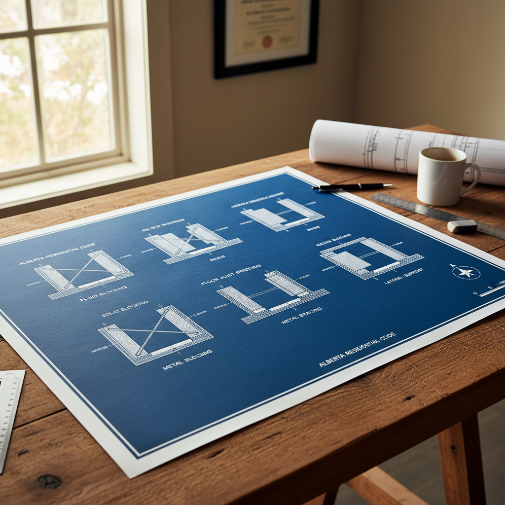
Twisting, squeaking, and bouncing in floor systems are more often symptoms than mere annoyances-they indicate underlying issues with lateral stability and restraint. Floor joist bridging and blocking, drafted and executed to rigorous code, directly influence how floors feel and perform in Alberta homes. Decisions made at the drafting table set the stage for durability, comfort, and safety, and understanding each code line-not just as rule, but as reason-is central to building floors that last.
Bridging vs. Blocking: Definitions, Differences, and Where Each Excels
In lumber-framed sub-floors, the wood joists that span supports require lateral restraint to maintain their structural orientation long-term under live and dead loads. The two principal methods used in Alberta residential drafting are bridging and blocking:
- Bridging: Diagonal bracing members (wood or metal) installed between two adjacent joists, often in an "X" configuration, to create triangulation against twisting or buckling. These can be installed either as continuous rows or between specific joists at prescribed intervals.
- Blocking: Solid blocks, typically matching the joist’s full depth, fitted snugly and at right angles between joists. These can be installed as a single row near supports or at intervals, or as multiple staggered rows along a span.
While both methods restrain joists, their application can depend on framing style, span, accessibility for other trades, and code-driven requirements in relation to finishes and loads. Bridging-especially metal bridging-can be faster to install in some retrofit scenarios or remodeling work, while blocking tends to offer superior resistance to heavy point loads, making it a preferred strategy near bearing walls or heavily trafficked parts of the floor.
Why Bridging and Blocking Matter in Alberta’s Housing Context
- Alberta’s climate and soil conditions, marked by freeze-thaw cycles, swelling clays, and long, dry winters, exacerbate structural stresses. Joists restrained at their ends, but allowed to twist or flex laterally in their mid-span, are more susceptible to movement over time as foundations settle or expand and contract seasonally.
- Open-plan architecture and the popularity of long spans in new Canadian residential design place increased importance on robust mid-span restraint, since fewer supporting walls mean joists are exposed and under greater unbraced length.
- Market demand for quiet, “solid” floors puts pressure on both builders and drafters to deliver floor assemblies with minimal bounce, vibration, and noise-criteria strongly impacted by what lies between the joists.
Deep Dive: NBC(AE) 2023 Code on Floor Joist Bridging and Blocking
Alberta’s National Building Code 2023 Edition (NBC(AE) 2023) inscribes prescriptive requirements that dictate when, where, and how to restrain floor joists. Two key articles-9.23.9.3 and 9.23.9.4-set out precise expectations, giving architectural drafters (and by extension, their clients) clarity to integrate code-compliance from schematic layouts through to construction documents.
Joist End Restraint: NBC(AE) 9.23.9.3
Every floor joist must have its bottom edge restrained at each end. The code allows several equivalent approaches:
- Toe-nailing the joist ends to the support beam or wall plate-a method as old as balloon framing itself.
- End-nailing joists into header joists; typical at floor perimeters or in platforms supporting stairwells.
- Continuous strapping, blocking, or cross-bridging-all near the supports, with precise specifications defined elsewhere in the code.
The logic: Joists, if unrestrained at their ends, tend to roll or twist under concentrated loads, especially in long runs. Mechanical fastening (toe- or end-nailing) is often reliable, but drafters should detail additional blocking or bridging, especially where supports are interrupted (for example, over beam pockets or where ductwork/pipe runs pass through a bearing line), or when I-joists are used instead of dimensional lumber, as their flanges may have reduced nailing surfaces.
Mid-Span Restraint: NBC(AE) 9.23.9.4
This article provides granular guidance, including precise sizing, spacing, and fastening rules for mid-span restraint:
- Strapping: Minimum 19 mm by 64 mm, applied to the underside of joists, max 2,100 mm (2.1 m) from each support or previous row. This option is traditional but can conflict with mechanical runs in floors.
- Bridging: Either 19 mm by 64 mm, or 38 mm by 38 mm (the latter for more robust restraint), also at max 2,100 mm intervals. May be industry-fabricated from wood or pre-engineered metal members.
- Blocking: 38 mm thick solid blocking matching the joist depth, located no more than 2,100 mm from supports or other rows; always securely fastened.
Where both strapping and bridging are required (some table-driven cases), strapping is positioned under the bridging unless replaced by compliant furring strips or a direct-attached panel ceiling. The code makes exceptions for some floating floor or engineered systems, but for most residential construction in Alberta’s wood-frame context, the combined system is commonplace-especially in larger, multi-story builds with complex layouts.
Why 2,100 mm Maximum Intervals?
The 2,100 mm rule is not arbitrary; it’s rooted in empirical performance testing and long-term building science. This spacing limits the unbraced length of joists, which otherwise would be susceptible to lateral buckling under concentrated or moving loads. In real-world terms, failure to honor this interval means a floor that may deflect over time-not just “bouncy,” but at genuine risk of splitting, warping, or outright failure under heavy traffic or furniture loads.
Drafting Practice: Step-by-Step Detailing for Code-Compliance
Accurate, readable drafting documents (digital or traditional) make the difference between a smooth build and costly or unsafe improvisations on site. Architectural drafters in Alberta consider not just code wording, but also practical, trade-friendly layout.
1. Assess Joist Layout: Dimensions, Spans, and Bearing
- Span: Before placing any bridging or blocking in a floor framing plan, verify the joist material, size, and spacing against table values from the code (and manufacturer data for engineered products). The longer the span, the greater the need for intermediate restraint.
- Supports and Load Paths: Identify all bearing walls, beams, pockets, and cantilevers. Points where joists are interrupted (bathroom floor cut-outs, HVAC ducts, stair openings) are especially prone to movement, demanding added attention to blocking layout.
2. Choose Bridging or Blocking with Mechanical Coordination in Mind
- Blocking: Solid blocking may be the default, but creates “hard paths” that can impede ductwork, piping, or electrical runs. In heavily-serviced areas (kitchens, laundry rooms, mechanical rooms) drafted layouts should anticipate conflicts by either:
- Staggering blocking above/below joist centerline for clear runs.
- Pre-punching service holes where possible, maintaining code-required clearances from blocking edges.
- Substituting bridging where solid blocking would otherwise create MEP obstacles, provided load/deflection criteria are still satisfied.
- Bridging: More “see-through” than blocking, and often easier for retrofit or renovation. Metal bridging is slim but can carry noise transference; wood bridging damps vibration but can be awkward in tight bays. Drafting should note specific bridging detail, including member material and fastening schedule.
Expert insight: In large custom homes, the best practice may be to combine strategies-blocking near supports for maximum base restraint, with bridging or strapping for mid-span coverage-drafted in clear sectional details keyed to floor plans.
3. Detail Code-Compliant Dimensions and Spacing
- Block Size: Specify blocking made of 38 mm thick lumber (i.e., actual 1-1/2 in width), cut accurately to the joist depth (usually 184 mm, 235 mm, etc. for standard 2x8, 2x10, 2x12), installed tight against both joists and fastened through vertical faces, not just ends.
- Bridging Size: Minimum 19 mm x 64 mm (nominal 1x3), or 38 mm x 38 mm (nominal 2x2); for engineered or composite joists, follow manufacturer’s bridging specs and detail clearly on plans.
- Interval: Always mark maximum 2,100 mm distance from support or previous blocking/bridging row. For joists exceeding 4,200 mm in full span, intermediate rows must be drawn in.
- Fastening: Detail the fastener type and pattern in schedules, with notations such as “Min. 2-16d nails per block, clinched when possible.” For metal bridging, list screw or nail size and frequency (e.g., “#8 x 38 mm wood screws, both ends, each diagonal”).
Best-in-class drafting overlays these dimensions not only in plan but in section/elevation views-dramatically improving clarity for framing crews and inspectors alike.
4. Accommodate Floor Finishes, Strapping, and Furring
- Where ceiling strapping (often for drywall finishing or sound attenuation) corresponds to required bridging, ensure these members are drawn on both the floor and reflected ceiling plans. Strapping may substitute if it meets code sizing and fastening rules, so call out alternate strategies in detail callouts.
- In basement or ground-floor assemblies with direct-screw or “panel-type” ceilings, note the substitution of furring or direct-applied sheathing per NBC(AE) 9.23.9.4.(5), which waives the strapping requirement in some cases. Drafters must cross-reference finish schedules with structural details to avoid field confusion and rework.
5. Stagger Rows for Advanced Load Distribution
- While code permits blocking/bridging in a single plane, especially for short spans, an advanced practice is to stagger adjacent blocks/bridges-installing them at varying distances from supports-especially in floors supporting heavy equipment (laundry machines, bathtubs, pianos).
- This approach, noted in drafting notes and isometric views, helps disperse concentrated loads and further reduces the chance of squeaks, which often originate from slight block movement or joist rubbing.
6. Specify Complete Fastening Schedule
- Do not simply note “nail in place.” Draft explicit fastener options (size, spacing, and type-nail vs. screw vs. mechanical connector). Confirm availability with local suppliers to minimize field substitutions.
- For engineered wood joists (I-joists, LVL), include connection diagrams showing approved mechanical fasteners or bridging hardware as recommended by manufacturers and accepted by inspectors.
Common Pitfalls in Drafting and Site Execution-and How to Prevent Them
- “Orphaned” Joists at Openings: Floor window and stairwell perimeters sometimes yield short “orphan” joists not easily tied into primary bridging rows. Detail blocking at these intersections with special attention-often requiring creative angled blocking or engineered solutions.
- Service Routing through Blocking: Mechanical trades may cut unapproved holes through blocking to run pipes, violating both code and engineering intent. Draft cutout sizes and locations, especially in tightly packed floor assemblies, and clearly indicate “do not cut” areas on plans.
- Underestimating Deflection: Code minimums protect basic structural integrity but do not always account for premium finishes. For high-end flooring (hardwood, luxury vinyl, tile), add notes recommending additional blocking/bridging in traffic zones, kitchens, or bathrooms, even where not specifically required.
- Fastener Substitution: Site substitutions (smaller nails, omitted screws) weaken blocking restraint. Draft explicit, standardized fastening callouts, referencing alternates agreed upon by competent structural engineers or building officials.
- Painting Over or Insulating Before Inspection: Ensure that floor assemblies remain open for inspection until after bridging/blocking has been verified by qualified personnel. Notate “Hold for inspector sign-off prior to ceiling closure” in the construction sequence on working drawings.
Engineering Insights: When to Exceed Code-Minimum in Alberta Projects
While the NBC(AE) 2023 establishes the legal floor for compliance, Alberta’s conditions and quality-conscious market often justify exceeding basic code. Drafters, in partnership with designers and engineers, should consider:
- Wider Joist Spans: For custom homes or multi-unit residential with spans well beyond 4,200 mm, doubling rows of bridging/blocking (or specifying engineered bridging systems) mitigates risks from springiness or unpredictable point loads.
- Vibration and Acoustics: Additional blocking decreases perceptible floor vibration and reduces the likelihood of nail pops in gypsum ceilings below-a key marketing point for upscale, noise-averse clients.
- Transfer of Shear Loads: In floors carrying significant lateral loads (long balconies, hurricane strapping near exterior wall lines), close attention to blocking layout can help distribute shear forces, strengthening the overall structure.
- Heavy Appliance Areas: In kitchens, laundry rooms, and baths, supplemental blocking beneath heavy fixed appliances (refrigerators, laundry pairs, soaker tubs) reinforces the floor, preventing sag or squeak despite years of loading.
Drafted notes can specify “additional solid blocking at all appliance locations, as required by equipment schedules,” with locations tied directly to MEP coordination plans.
Integrating Floor Joist Restraint Details with Full Permit Documentation
Permitting authorities throughout Alberta expect more than schematic representations of floor assemblies. Code-compliant, highly legible documentation of joist bridging and blocking is instrumental not only for approvals but for smooth onsite execution:
- Framing Plans: Each floor sheet to show size, material, and exact location of all bridging/blocking members, whether as lines, symbols, or embedded layer callouts.
- Construction Details: Enlarged sections to illustrate typical and atypical conditions-joist-to-support interfaces, blocking/bridging in joist bays interrupted by openings, and integration with dropped ceilings or bulkheads.
- Notes and Schedules: Clear written schedules align with graphic details, minimizing ambiguity and error. “Install 38mm solid blocking, full joist depth, max. 2,100mm from all supports and every 2,100mm along span unless otherwise noted.”
Drawings should highlight exceptions: where high steel beams, glulam, or point loads occur, detailing the alternate restraint or engineered solution avoids field improvisations prone to failure or later compliance issues.
Service Coordination: Trades, Openings, and Future-Proofing
Architectural drafting must look beyond the timber. The best blocking/bridging scheme is rendered ineffective if it creates friction with subsequent trades or prevents future upgrades. Key strategies include:
- Pre-coordination with HVAC, Plumbing, Electrical: Calls for regular pre-construction trade meetings-scheduled within the construction documentation-with blocking/bridging layouts available for markup and review. Digital models (BIM or 2D overlays) allow direct clash detection and resolution before framing materials are procured.
- Provisions for Access: Notate future access gaps or removable blocks in key bays, especially for custom homes expected to accommodate complex home automation, security, or water treatment installations over their service life.
- Fire and Sound Barriers: In multi-unit or suite-separated homes, ensure that any required fire/sound caulking or mineral wool insulation can be applied without compromising blocking/bridging strategies. Where fire rating is critical, specify fire-treated materials or additional layers as required by code.
Drafted documents should clearly indicate “NO CUT” or “SERVICE HOLE PERMITTED” on blocking elements and reference manufacturer’s guidance for engineered floor systems, ensuring that field crews are not left to guess after materials arrive onsite.
Inspectability and Sign-Off: Achieving Smooth Approvals
- Ensure all blocking/bridging is visible and accessible for city or municipal inspectors prior to installation of ceilings, insulation, or beneath-floor soundproofing. Where sequences make this difficult, instructional notes (e.g., “Inspector to sign off prior to closure of drywall”) should be called out with clarity.
- Annotated “as built” sketches-sometimes required for complex custom work-must include final blocking/bridging configuration and any deviations, approved and signed off to facilitate warranty and re-sale documentation.
For projects subject to home warranty programs or builder’s quality audits, comprehensive documentation is frequently a make-or-break factor should future claims or inspections arise.
Detail Matters: Kingsway’s Approach to Superior Floor System Drafting
Years of Alberta-specific drafting reveal common truths: The devil is in the details, and the difference between an average and an exceptional floor system is rarely evident in show homes, but always apparent to the long-term homeowner. Fine-tuned bridging and blocking not only fulfill code-they shape livability, resale value, and the overall “feel” of the home’s structure. Where possible, integrate above-code enhancements, builder-supplied notes on client priorities, and locally proven best practices-bringing field wisdom into every drawing.
- Include optional enhanced blocking in “high traffic” rooms, around heavy fixings, and spanning transitions between different joist sizes or types.
- Adjust layouts to favor accessible service chases, future proofing each design for mechanical and technical upgrades.
- Mount all blocking/bridging callouts in context, with references to enlarged details for special conditions (e.g., stairwells, utility chases, angled walls).
Locally accurate, code-compliant drafting of floor joist bridging and blocking is more than a code requirement-it's an essential design discipline that underpins every successful Calgary residential project, and it's a cornerstone of Kingsway Drafting & Design’s practice and reputation.