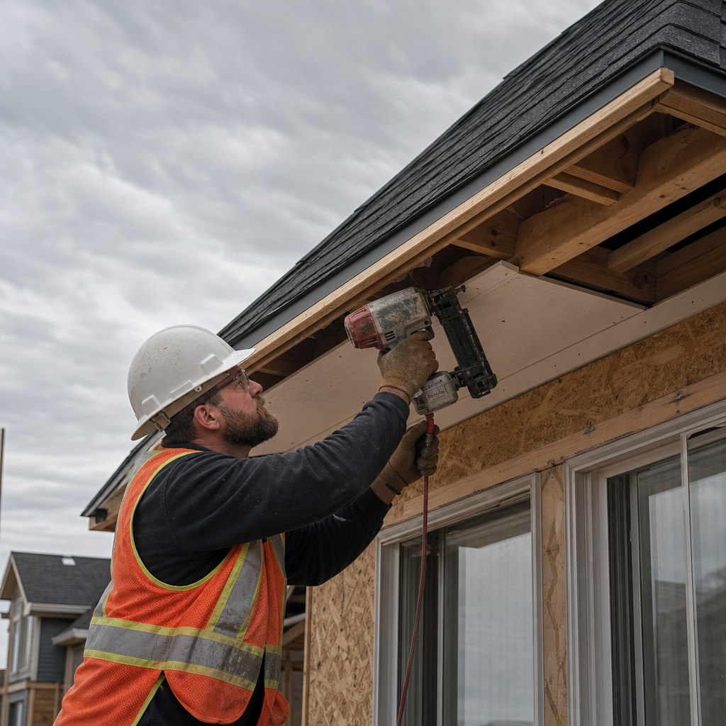
Fascia and soffit assemblies must be engineered and documented to achieve code-compliant wind resistance in Alberta homes. Drafters face the recurring challenge of linking Alberta Building Code (ABC) NBC(AE) section requirements directly to construction details, fastener schedules, and material specifications across plan sets. Plan review failures often result from non-specific code referencing, missing dimensions, and unclear sectioning-especially where high wind exposure, city zoning, and STANDATA amendments play a role. Robust, well-integrated construction documents remain the most reliable defense against both municipal redlines and jobsite failures.
Referencing Alberta Building Code Part 9 Prescriptive Requirements for Fascia and Soffit Wind Resistance on Drawings
Key ABC Section Call-Outs and Applying Prescriptive Tables
Fascia and soffit wind resistance requirements reside principally in Part 9 of the National Building Code - 2023 Alberta Edition (NBC(AE)), with several targeted sections providing the basis for prescriptive detailing. Correct citation is not optional-drawings that omit or incorrectly reference section numbers almost invariably see delayed plan reviews and extra redlines. The three core sections to cite on plan sheets are:
- Section 9.23.3.3. - Framing: Dictates framing member size, spacing, and nailing, which form the base for both fascia and soffit attachment.
- Section 9.27 - Cladding: Sets out the standards for materials and their joining/fastening; critically, 9.27.3 governs soffit and fascia materials and 9.27.5 specifies fastening-including minimum fastener type, length, and spacing.
- Section 9.27.12 - Metal: States the requirements for metallic soffit/fascia, with mandates such as CAN/CGSB-93.2-M conformance for aluminum products.
Additionally, Table 9.27.5.4. delivers explicit fastener sizing and spacing-for example, wood trims: 51 mm (2") nails at 600 mm (24") o.c. Taking these raw code tables and translating them into clear general notes or custom “Fascia & Soffit Fastener Schedules” on the construction drawings is a best-practice approach. A typical general note might read:
- “All fascia and soffit attachments to comply with NBC(AE) 9.27.5.4. Fastener type and spacing per Soffit & Fascia Fastener Schedule, Sheet A501.”
In wind-exposed regions, detailing should include explicit reference to wind load category or design wind pressure-either via an ABC table selection or, where relevant, engineered calculations. Typical call-out:
- “Wind resistance for fascia/soffit to meet Category B (ref. NBC(AE) Table 9.27.5.4.), Exposure C wind zone, as per Wind Load Map Sheet A002.”
Material and Fastener Redlines Common in Plan Review
Omitting fastener type/size, under-specifying spacing, or missing a code reference are issues flagged routinely by municipal reviewers:
- “Provide fastener schedule for all fascia and soffit. Typ.”
- “Clarify compliance with NBC(AE) 9.27.12.1. for metal fascia-list aluminum gauge.”
- “Design does not demonstrate wind load compliance at eaves-provide analysis or increase fastener frequency.”
Addressing these in a pre-emptive manner by embedding code-referenced detail keys, fastener tables, and labeled material specifications at each relevant detail avoids costly resubmission cycles.
Standard Drawing Conventions: Code Sections, Schedules, and Details
Effective communication starts with clarity and specificity. Construction documents for Alberta best practice:
- Code References: “FASCIA ATTACHMENT - SEE DETAIL 9/A503, ALL ATTACHMENTS NBC(AE) 9.27.5.4.”
- Fastener Schedules on Sheet A501 or A600: Table formatting, listing material (e.g., wood fascia, alum. fascia, fiber cement), min. fastener length, type (corrosion or non-corrosion), and on-center (o.c.) spacing, cross-referenced to wall/roof assemblies and wind zone.
- Large-Scale Details: (E.g., 1.5" embed into sub-fascia, 24" o.c. min. for standard, 16" o.c. max. for high-wind; show fastener patterns at splice and corner boards; highlight critical vapour/vent paths adjacent to eave closure.)
Standardizing material specification per CAN/CGSB references (e.g., “Pre-painted aluminum fascia and soffit to CAN/CGSB-93.2-M, min. 0.48 mm thick”) on plan legends reduces ambiguity at review and in the field.
Granular Detailing and Dimensioning of Fascia Board Attachment for Enhanced Wind Uplift
Fastener Types, Sizes, and Spacing for Various Fascia Materials
The interface between fascia and its substrate (rafter tail, sub-fascia, or blocking) is a primary structural defense against wind-induced eave failure. Robust detailing not only ensures code compliance but also survives Alberta’s high-wind events. For wood fascia, 10d ring shank nails (3", 76 mm) or #10 screws remain the gold standard, with stainless steel mandatory for prolonged life, especially in coastal zones or regions exposed to frequent wind-driven rain. For fiber cement fascia, manufacturers (e.g., James Hardie) typically require #8 or #10 corrosion-resistant screws, pre-drilled at 406 mm (16") o.c. maximum. Aluminum and steel-wrapped fascias depend on finish nails or specialty trim screws, always corrosion-proof.
Drafted dimensions and drawing call-outs must specifically indicate:
- Standard wind exposure: 24" (610 mm) o.c. max;
E.g., “WOOD FASCIA - 10d ring shank nails @ 24" o.c., min. 1.5" embed into sub-fascia, staggered pattern.” - High-wind exposure: 16" (406 mm) o.c. max for all fasteners. (Ref. regional STANDATA for wind mapping.)
- Edge distance: 1" (25 mm) min. from board edge;
“All fasteners to maintain 25 mm edge distance from board/trim per NBC(AE) best practice.”
Fastener length is equally critical; all must penetrate a minimum of 1.5" (38 mm) into solid wood substrate, called out in both the fastener schedule and enlarged section details.
Material-Specific Connection Detailing and Splice/Corners
Wood fascia attachment relies on a continuous sub-fascia: “Install treated 2x4 sub-fascia to rafter tails with (2) #10 screws per tail, then attach fascia board with 10d nails @ 16" o.c. for high wind.” Fiber cement boards mandate pre-drilling to prevent splitting: “Hardie fascia: #10 SS screws through pre-drilled holes @ 406 mm o.c., min. 1.5" embedment, all cut ends primed.”
For metal-wrapped (aluminum) fascia:
- “Fascia cap to extend min. 25 mm beneath drip edge, fasten top edge with aluminum trim nails @ 6" (152 mm) o.c. at utility trim. Lock fascia with snap-lock punches max. 6" o.c. at all exposed edges.”
Where fascia must be spliced, detail a scarf joint with 2" (50 mm) min. overlap, secured by two fasteners on each side, joints offset from sub-fascia splices by at least 150 mm to stagger seams and maintain rigidity.
At all corners, call for tight mitre cuts and additional backing: “Corner detail - mitred fascia with concealed blocking at inside angle, (2) fasteners at each return.” These specifics are best illustrated with cross-referenced details (e.g., Detail 6/A506: Fascia Corner Reinforcement).
Detailed Soffit Panel Attachment Strategies and Drawing Call-Outs for Wind Resistance
Attachment Directives for Vented Aluminum, Vinyl, Wood, and OSB Soffits
Soffit panel selection and attachment vary by exposure and architectural design, but robust wind resistance in Alberta demands methodical sectioning and code-specific call-outs in all drawings. Plywood and OSB (min. 3/8" - 7/16") require direct nailing to blocking or framing at 6" (152 mm) o.c. on edges, 12" (305 mm) in field as a minimum. For vented aluminum or vinyl, fastener selection must suit panel profile and manufacturer nuance, but the standard includes: “Alum. soffit to J-channel + blocking, fastened w/ #8 pan-head screws, corrosion-resistant, at 12" o.c. perimeter and every support.”
Jobsite complaints about ‘loose’ or ‘fluttering’ soffits are almost always traced to skipped blocking or shortcut fastener placement-something easily corrected by explicit plan detail. A common mistake is spacing supports at rafter intervals rather than code-mandated maximums, meaning:
- For spans > 12" (305 mm): “Intermediate 2x2 nailing strips between trusses/blocking @ 16" o.c. max required beneath all continuous soffit runs.”
At gables and intersections, highlight the function of J- and F-channels both on plan and in section:
- “Install J-channel continuous at house wall and fascia, F-channel as required at out-of-plane intersections; soffit panel ends fully engaged, no unsupported span > 305 mm.”
Specific fastener schedules in drawings typically state:
- Metal/vinyl soffit: 1" (25 mm) aluminum or SS screws/nails, 12" (305 mm) o.c., both ends, plus field supports for spans > 305 mm.
- Wood/OSB soffit: 2" (51 mm) common nails, 6" (152 mm) o.c. at edges, 12" (305 mm) in field, minimum embedment 38 mm into wood blocking or joist.
Blocking and Panel Support at Gables and Roof-to-Wall Junctions
Drawing details must show continuous 2x4 (nominal) blocking at all soffit perimeters and every intermediate support point exceeding manufacturer’s span rating. Redlines often flag:
- “No blocking shown at gable return. Provide detail or keyed note.”
For high-wind exposure, add reinforcement at panel terminations: “Provide 2x4 backing at all wall/soffit intersections-fasten with 16d nails @ 24" max o.c., verify end grain blocking at gable rakes.” This is best illustrated with large-scale details keyed from plan and wall sections, preventing both review delays and installation ambiguity.
Anticipating Plan Review Redlines and Incorporating Jobsite Quality Control Notes for Eave & Soffit Wind Compliance
Common Plan Review Redlines and Drawing Deficiencies
Reviewers consistently raise the same deficiencies when reviewing Alberta eave assemblies:
- Omission of a detailed fastener schedule, forcing a return for clarification.
- Insufficient blocking details, or missed indication of intermediate supports where span limits are exceeded.
- Material call-outs not referencing CAN/CGSB-93.2-M or incorrect aluminum thickness/gauge shown on drawings.
- Soffit ventilation details missing, leading to attic vent code non-compliance alongside potential wind vulnerability.
Typical municipal redline examples include:
- “Blocking not shown @ 24" o.c. for vented soffit. Revise.”
- “No fastener spacing for aluminum fascia - reference NBC(AE) 9.27.12.1.”
- “All attic vent areas at eaves to show calculation for 1/300 compliance.”
Proactive Drawing Notes and Onsite Verification Points
Adding targeted general notes and QC checklists to sheets such as A501 (construction details) and A002 (general notes/legend) pre-empts most redlines and sets the stage for code-compliant installation:
- “All fasteners for fascia/soffit components to be corrosion-resistant, min. 1.5" (38 mm) length, 1.5" embedment min., per NBC(AE) 9.27.5.4.”
- “Verify at field: All soffit panels fully engaged in receiver/track, no edge span unsupported > 300 mm. Inspect every run before closure.”
- “Continuous 2x4 SPF or LVL blocking at all soffit panel terminations and at intervals not exceeding 600 mm (24").”
- “Soffit and fascia materials to be CAN/CGSB-93.2-M compliant; confirm aluminum gauge (0.019” min.).”
- “Install vented soffit to achieve 1/300 attic net free vent area, maintain clear baffle at eave, insulation not to obstruct vent path per NBC(AE) 9.19.1.2.”
Inspection tags (“Verify 1.5 inch minimum fastener embedment”, “Continuous backup blocking present at gable returns”, “No unattached field edge soffit panels”, etc.) should be listed in jobsite documentation and referenced from plan set general notes or on large-scale details.
Embedding these notes in drawings-especially under a “QUALITY CONTROL & INSPECTION NOTES” heading-provides the clarity field supervisors need to recognize non-compliance before municipal inspectors do.
Sample Fastener and Blocking Schedules
Standard plan sheet tables should appear as follows:
- Fascia (wood): 10d ring shank nail, 76 mm (3”) length, 1.5” embedment, @ 406 mm (16”) o.c. for high-wind, 610 mm (24") o.c. standard.
- Soffit (metal): #8 self-tapping screw, 25 mm (1”) length, 305 mm (12”) o.c. at panel ends, intermediate support at 600 mm (24”) max.
- Blocking: 2x4 SPF, continuous at soffit perimeter, additional at 600 mm (24”) intervals for vented or field-panel support.
Integrating Comprehensive Fascia and Soffit Wind Details into a Unified Plan Set
Cross-Referencing and Sheet Organization
Achieving consistent, review-ready documentation depends on precise cross-referencing and logical organization. Start by referencing fascia and soffit wind-resistance requirements on the roof plan (A100-A102)-locations of fascia and soffit are indicated with tag numbers or keynotes linking back to details and schedules (e.g., “Fascia/Soffit Assembly - SEE SCHEDULE A501, DETAILS 5/A502, 7/A506”). On wall section sheets (A301-A305), show full-depth assemblies with joists/trusses, sub-fascia, blocking, and precise fastener call-outs with code section references packed into each label.
Large-Scale Details (A502-A506) offer exploded views at eave corners, mid-field attachments, or at transitions from roof to wall or gable rake. These must show:
- Exact material composition, thickness, and gauges (e.g., “Aluminum fascia capping, 0.024" min. (0.61mm), CAN/CGSB-93.2-M”)
- Fastener type/size and pattern for each material layer (e.g., “#7 SS trim screws, 6" o.c. at upper edge, concealed, see schedule”)
- Insulation, air/vapour barrier interface, vent path, baffle location and dimension (ref. ABC 9.19.1.2 for eave ventilation)
Drawing sets must also cross-link to the site plan and provide zoning overlays on eave/soffit encroachments:
- “No soffit within 0.45 m of property line per Calgary MDP; unvented only within 1.2 m, minimum .5" plywood or equivalent, sheet steel, or unvented aluminum.”
Reiterate all these elements in both the general notes section (A002) and as keynotes attached directly to assemblies in plan, section, and detail views.
Keynote, Schedule, and Legend Techniques for Consistency
To minimize confusion for builders, inspectors, and reviewers, use unambiguous keynotes attached to plan elements:
- “Keynote 14A: Install fascia board with 10d ring shank nails, 406 mm o.c. max.; see A501 Fastener Schedule, Sheet A502 Details 3 & 6”
- “Keynote 16B: Provide aluminum vented soffit, CAN/CGSB-93.2-M, attachment per Fastener Schedule, all ends engaged in J-channel, 305 mm field support max.”
Include a dedicated Fascia & Soffit Fastener Schedule with columns for:
- Component (wood fascia, aluminum wrap, etc.)
- Wind zone (standard, high-zone per site wind map)
- Fastener type/size (shank/nail/gauge/screw)
- Spacing (o.c.)
- Embedment/penetration
- Code section reference
On every drawing set, supply a legend decoding all abbreviations (SS - stainless steel; CAN/CGSB - Canadian General Standards Board; VSO - vented soffit opening, etc.) as well as material tags keyed to the schedule and notes. This unified approach ensures clarity from concept through construction.
Layering General Notes, Material Specs, and Connection Requirements
General notes belong at the front of the set and cover fundamental compliance statements-e.g., “All work to conform to NBCAE 2023, STANDATA amendments, and local zoning as shown.” Material specifications must state both ABC qualitative and quantitative requirements: “Aluminum soffit 0.019” (0.48 mm) min. per NBC(AE) 9.27.3.7., vented, CAN/CGSB-93.2-M, color as schedule.”
Connection requirements demand their own section in each fastener/material schedule and should cross-reference detail numbers as required. Critical tie-points, such as “Scarf joints at fascia: overlap 2" min., 2 fasteners per side, all cut ends sealed,” ensure installers and inspectors understand exactly what’s required for a wind-compliant assembly.
Attic ventilation, zoning, and other province-city overlay compliance (e.g., Calgary: “No perforated soffit in eaves within 1.2 m of property line, use unvented aluminum, or ½” min. plywood, OSB, lumber, or sheet steel.”) should be visually highlighted where risk of reviewer oversight is greatest (e.g., sheet A002 zoning notes, detail call-outs at eave overhang/jurisdiction line).
Dimensions, Ratings, and Critical Material Specifications
Dimensions, ratings, and material specifications must be explicit:
- Vented soffit profiles: 4", 6", 8", and 10" (aluminum/vinyl) to CAN/CGSB-93.2-M, confirm all sizes in legend and schedule. (Skyview Star Exteriors)
- Aluminum fascia capping: 0.024” (0.61mm) in wind-exposed locations, 0.019” (0.48mm) minimum base everywhere (Skyview Star Exteriors).
- Fastener call-outs: “All fasteners to be corrosion-resistant, sized per schedule, spacing not to exceed code or manufacturer limits.”
Where unique roof shape, parapet, or wall intersection conditions exist, supplement base assemblies with enlarged details and specific dimension call-outs (e.g., “minimum 63 mm cavity between insulation and roof sheathing at eave/baffle area, per NBC(AE) 9.19.1.2.”)
Conclusion
Effective drafting for fascia and soffit wind resistance is rooted in unambiguous code section referencing, granular dimensional detail, and the strategic use of schedules, notes, and cross-referenced large-scale details across every sheet. Embedding requirements directly, citing specific NBC(AE) (e.g., 9.27.5.4., 9.27.12.1., 9.19.1.2.), specifying fastener and material dimensions by Alberta standards, and anticipating both municipal redlines and site QC routines delivers the best outcomes-for permit approval and for long-term house performance in Alberta wind. For planned excellence and smooth review, Kingsway Drafting & Design brings these standards to every Calgary plan set.