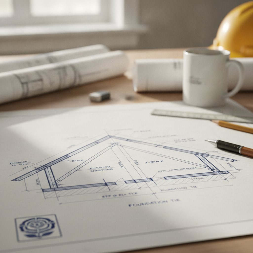
Gable end walls, defined by their characteristic triangular shape formed at the ends of sloped roofs, serve vital structural and enclosure roles in every wood-frame home with a pitched roof. Their geometry and position expose them to higher lateral forces, particularly from wind, making them frequent points of failure in severe weather. Alberta’s climate, marked by strong Chinook winds, storms, and regional seismic considerations, demands meticulous attention to proper bracing design and documentation. While the National Building Code - 2023 Alberta Edition (NBC(AE) 2023) provides comprehensive frameworks, the correct application of its requirements at the drafting and construction stages determines the safety, durability, and code compliance of the entire structure.
Gable End Wall Vulnerabilities: Why Bracing Matters
The planar surface of a gable end wall acts as a broad sail in the face of wind loads. Unlike full-height walls, the upper triangular portion has limited internal support because roof trusses or rafters terminate at the wall top plate, with the gable wall extending upward, often as a non-loadbearing assembly. This configuration makes it more flexible and prone to lateral movement, racking, or even complete blow-out if not correctly braced. Failures at the gable end compromise roof integrity, precipitate water intrusion, and can lead to progressive collapse. Ensuring that lateral forces from wind and, in some Alberta regions, seismic events, are safely transferred through the wall’s framing and sheathing into the rest of the building is both a code and a practical necessity.
Code-Driven Principles for Gable End Wall Bracing
The NBC(AE) 2023 addresses wall bracing in detail, particularly in:
- Section 9.23.13: Bracing to Resist Lateral Loads Due to Wind and Earthquake - Stipulates band and panel bracing schemes for wood-frame construction, specifying the amount, location, and connectivity of bracing required to achieve wall stability.
- Section 9.23.10.2: Bracing and Lateral Support - Mandates diagonal bracing for exterior walls not otherwise fully sheathed or clad with code-approved materials, with precise requirements for member size, angle, and nailing.
The code sets design-level expectations but leaves the precise detailing to qualified drafters and designers supported by structural engineering insight as required by the scope of the project.
Sheathing Strategies: Material Selection and Fastening Techniques
Robust gable end wall sheathing provides the most direct resistance to lateral forces. Under NBC(AE) 2023 requirements, structural panels such as plywood, oriented strand board (OSB), or waferboard, minimum 9.5 mm thick, are widely recognized for their shear-resisting characteristics. Sheathing not only supports bracing but also provides a nail base for siding and air-barrier layers. Properly documented sheathing details-inclusive of specified panel thickness, grade, and fastener size and pattern-are essential for a valid permit submission and for clarity on site.
- Panel Thickness: Minimize deflection and maximize lateral stiffness with minimum 9.5 mm thickness.
- Fastening Schedule: Reference NBC(AE) 2023 Table 9.23.3.5.A. For most structural applications, edge nailing at 150 mm o.c. and field nailing at 300 mm o.c. with 2.87 mm diameter nails or equivalent screws is typical. Accurate annotation prevents under-fastening on site.
- Panel Orientation: Install panels with the long dimension perpendicular to studs. Stagger vertical joints where possible to avoid creating “hinged” weaknesses. Annotate sheathing layout clearly in wall section and elevation details.
Practical Detailing for Sheathed Gable End Walls
Construction drawings should unambiguously illustrate:
- Sheathing type (e.g., “9.5 mm OSB APA-rated sheathing, panel edge supported”);
- Nominal stud spacing (commonly 400 mm o.c. or 600 mm o.c.);
- Attachment schedule (exact fastener length and spacing at edges and in fields);
- Transition details at wall-to-wall and wall-to-roof interfaces to ensure airtightness and structural continuity.
For increased resilience, drafters often specify an additional bead of construction adhesive behind sheathing at critical points-a minor cost, major benefit step increasingly adopted in Alberta best practice.
Diagonal Bracing as Structural Insurance
While continuous sheathing offers superior lateral resistance, the NBC(AE) 2023 allows for (or requires, in some cases) diagonal bracing in situations where the wall is not otherwise fully supported. In practice, diagonal bracing often complements sheathing, especially in the gable peak region where wall height exceeds the reach of internal partitions or where there are frequent window openings.
- Minimum Member Size: Diagonal braces must be at least 19 mm by 89 mm (actual dimensioning is critical-nominal size does not suffice for code).
- Angle of Installation: Install at approximately 45° to the horizontal for maximum racking resistance; nonconforming angles reduce effectiveness and may draw inspection comments.
- Continuous Length: Each brace should run the full height of the gable wall segment between plates-repeat on each storey if multi-level.
- Nail Attachment: Requirement is minimum two 63 mm nails at every stud and where intersecting top and bottom plates, ensuring full bearing into framing members.
Diagonal brace layout is best shown both in plan (for orientation/extent) and elevation (to clarify upper and lower anchor points). Each brace location should be coordinated to avoid interference with planned fenestration, ducts, or plumbing runs-requiring close coordination between the drafter, designer, and builder.
Optimizing Diagonal Bracing at the Gable Peak
The uppermost gable region is most vulnerable due to reduced internal partition resistance. Where high wind zone or non-engineered conditions prevail, consider doubling diagonal braces in each direction or using “X” bracing (cross-brace pattern). All such systems must still meet the prescribed nailing and connection requirements, with careful notation of sequencing to avoid onsite misinterpretation.
Continuous Load Path: Securing Gable Wall to Roof
A critical aspect of code-compliant bracing is not just stiffening the gable wall itself, but also ensuring loads transfer without interruption into the roof and attic framing. Gable end wall failures during storms are frequently traced to poor connections at wall-to-roof interfaces-often when builders rely solely on toenailing.
- Metal Connectors/Straps: Specify code-listed hurricane ties or metal straps that tie the gable top plate(s) to either roof truss chords or rafter ends, extending over at least two adjacent framing members for redundancy.
- Fastener Type and Schedule: Use connectors with prescriptive fastener patterns, not just “as required”-for example, Simpson Strong-Tie H2.5A or equivalent, using specified nails (not screws unless approved by connector manufacturer and code official).
- Bracket Placement: Detail the minimum number and spacing of connectors along the gable plate, especially at points above large window or door openings where wall strength is reduced.
Drawings must unambiguously indicate attachment at both ends and supplemental hardware where gable peaks exceed standard heights, or where unusual roof-to-wall intersections occur (e.g., truncated gables, intersecting roof planes).
Drafting for Load Path Integrity
Section details should illustrate the connector running from the gable wall plate, up and over to the roof truss or rafter tail, with fastener callouts and reference to manufacturer booklet if applicable. Coordination with truss design drawings ensures that such connectors do not conflict with other roof hardware or lead to unintended horizontal crushing in the top plate under load.
Lateral Bracing: Extending Stability Beyond the Wall Plane
Lateral bracing, installed perpendicular to the gable end wall and connected to the broader attic or ceiling structure, is a powerful but sometimes underutilized strategy for mitigating sway and racking in gable assemblies. Pressure from wind or dynamic loading is absorbed across a larger area and dissipated through the building frame, lessening localized stress and improving overall resilience.
- Horizontal Bracing Placement: Install braces at the ceiling joist or truss bottom chord level and, when practical, at the upper rafter or top chord adjacent to the peak. Placement at both elevations is especially valuable for walls over 3 feet high above the wall top plate (as per recommendations from Building America Solution Center).
- Connection Technique: Attach horizontal bracing using three #8 x 3-inch screws at each intersection-screws should penetrate fully and avoid interference with electrical or mechanical runs.
- Material Choice: 38 x 89 mm lumber is a typical minimum; engineer-specified species and grades may be requested for long spans or high-load roofs. Metal strapping may be added as a supplement but is not a replacement for solid bracing lumber.
- Bracing Orientation: Extend lateral bracing across a minimum of three truss bays, but ideally as far into continuous ceiling space as practical; avoid creating large unbraced spans behind gable wall.
Well-executed construction drawings will show horizontal bracing in both plan (attic/ceiling framing) and gable wall elevation. Elevations should include clear callouts for fastening, lumber size, and interface with ceiling or truss framing to prevent confusion during framing inspections.
Addressing Tall Gable End Walls with Retrofit Strategies
In many Alberta homes-especially those with vaulted or cathedral ceilings, or in older stock with enlarged attic spaces-gable end walls frequently rise well over heights addressed by simple single-level bracing. Bracing details for such conditions must address:
- Vertical Retrofit Studs: For gable ends taller than 48 inches, install vertical “retrofit” studs adjacent to each existing gable wall stud. These provide increased support for both sheathing and lateral bracing. Drafters need to detail stud size (matching or exceeding existing gable stud size, typically 38×89 mm or greater), length, and offset (tight against or maximum 1/8 inch gap at lower brace, 1/2 inch at upper, as per leading research guidance).
- Attachment Details: Use #8 x 3-inch screws at 6 inches on-center to secure retrofit studs to both horizontal bracing and original wall studs. Where practical, cross-nail for increased strength but avoid over-screwing, which can split framing in dry winter conditions. Specify metal straps between each retrofit stud and horizontal bracing, noted clearly in both section and plan drawings.
- Compression Blocks: Place compression blocks on horizontal bracing bearing tightly against retrofit studs, attached with three #8 x 3-inch screws each-avoid penetrating strapping, which might compromise its function. Drafters should illustrate compression block placement at each retrofit intersection, especially at high gable points.
For mid-century home retrofits, where existing framing dimensions or spacing may not match modern code, construction drawings should include full-size “as found” measurement callouts and a schedule for replacement or reinforcement of nonconforming members, flagged for field verification.
Sequencing and Installation: Beyond Code Minimums
Effective bracing begins on the plans. Annotate sequence of assembly-sheathing before or after horizontal/lateral bracing, for instance-minimizing field improvisation and potential for omitted steps. Where multiple trades share responsibility (framers, strap installers, roofers), designate scope and timing for each component in construction notes. This level of clarity prevents costly delays and inspection failures.
Accounting for Alberta’s Wind and Seismic Realities
Alberta is subject to a spectrum of climatic loads, with particularly aggressive wind exposure in southern and central regions due to open prairie terrain, and a low but not negligible risk of seismic events along the foothills. The NBC(AE) 2023 establishes minimum thresholds for bracing based on wind speed and other site-specific parameters. Drafters must:
- Determine the site-specific wind basic pressure (q1/50) for each project-commonly referenced in site data or requested from engineering partners;
- Increase bracing area/frequency and upgrade connection hardware in exposed or high-load sectors;
- Add supplementary measures where code-mandated bracing is insufficient due to unusual exposure-such as corner lots, large unbalanced gables, or complex roof intersections;
- Reference site wind exposure class and seismic hazard level in every code summary note for easy building official review, flagging bracing upgrades where required by Part 4 engineering or local bylaw variations.
Far from creating excess paperwork, these details demonstrate up-front attention to safety and help streamline both permitting and field inspection processes-often preventing costly rework or bracing retrofits after occupancy.
Quality Assurance at Construction: Bridging Plan and Execution
No set of plans, however precise, is self-enforcing onsite. Long experience in Alberta construction has shown that gable end wall bracing is most often compromised not by standard design but by incomplete or ambiguous detailing and by construction shortcuts in fastener selection, bracing orientation, or connection integrity. To ensure full benefit from rigorous drafting, consider the following best practices:
- Specify All Fasteners and Connections: Generic “nail as required” notes are insufficient. Specify every fastener size, type, and location, including where purpose-designed screws or hardware should be substituted (e.g., engineered wood products, high-exposure areas).
- Include Field Verification Details: Encourage inclusion of “as-built” checks for critical bracing-such as photographs or inspection forms-especially on custom or high-value projects.
- Provide Sequencing Diagrams: Many framing errors occur simply because assembly sequence is unclear. Simple isometric diagrams, included as callouts in the bracing detail sheets, help translate plan intent to practice.
- Document All Variations: In field, alterations are sometimes unavoidable due to unforeseen framing conditions. Plans should direct changes to be reported back for updated documentation and, where needed, engineered review.
Expert Insight: Drafting Questions and Coordination
From the drafter’s vantage, code compliance for gable end wall bracing begins with asking the right coordination questions at schematic stage:
- Are there oversized windows or doors in the gable end wall that reduce viable framing/brace locations?
- Is the wall a high-wind exposure, or does it serve an attached garage or “bonus room” configuration with non-standard ceiling heights?
- Has engineered roof truss or rafter design already been completed and issued for review-to cross-check compatibility with bracing hardware or straps?
- Do the attic geometry or insulation strategy (e.g., high heel trusses, ventilated eaves, or spray foam) conflict with lateral bracing locations?
- Are there future expansion, solar, or wind-driven equipment plans that will alter load patterns at the gable?
At Kingsway Drafting & Design, these considerations form part of an integrated checklist discussed at kickoff with both client and builder/GC, ensuring that all potential bracing complications are fully surfaced before finalizing permit drawings.
Permitting and Inspection: Clearing Regulatory Hurdles
City and municipal plan reviewers in Alberta are highly attuned to the risks associated with wind and storm damage, and code compliance around gable wall bracing is a frequent point of permit scrutiny. Submittals most likely to pass “first try” demonstrate:
- Complete bracing schedules cross-referenced from wall sections and framing plans;
- Clear fastener callouts (nail/screw type, size, spacing) on every bracing component drawing;
- Design notes referencing the applicable NBC(AE) 2023 clauses-matching language used by inspectors and code officials;
- Identification of all proprietary hardware or engineered components, with embedded manufacturer cut sheets if used (e.g., strap anchors, retrofit connectors);
- Sequence notes qualifying when bracing must be completed (prior to sheathing, after window installation, etc.);
- Annotation of wind/seismic class for clear jurisdictional reference.
Proactively including these elements in drafting packages minimizes the “clarification requests” cycle, accelerates permit issuance, and fosters good working relationships with local officials who know your documentation is thorough and trustworthy.
Cost, Constructability, and Value: The Drafter’s Balancing Act
Effective gable end wall bracing must balance several concerns:
- Cost-Effectiveness: Higher-grade sheathing or additional hardware increases upfront costs, but failure to brace correctly can multiply repair and insurance costs exponentially after severe weather. Drafters aim for least-cost-compliant solutions with options for “good, better, best” depending on owner or builder budget and risk tolerance.
- Ease of Construction: Details should account for Alberta winter framing realities: deep cold, fast build cycles, wet/dry wood movement. Avoid calling for complicated “custom” framing assemblies unless absolutely required-choose standardized, locally available products and techniques when possible.
- Future-Proofing: Gable end walls frequently serve as mounting bases for future solar panels or vent penetrations. Bracing over-engineered at an early stage can avert expensive reinforcement later, especially in regions likely to be targeted for future upgrades.
- Insurance and Warranty Implications: Increasingly, insurers and home warranty providers review drawings for evidence of robust lateral load detail, especially in regions with prior storm claims. Documenting best-practice bracing earns easier underwriting and greater peace of mind for all parties.
Case Studies: Applying Code-Compliant Bracing in Practice
Example 1: New Build, Calgary Suburb, Standard Gable Roof
Working on a two-storey home with a conventionally framed gable roof and full attic, Kingsway Drafting & Design produced a bracing package featuring:
- Full-height 11 mm OSB sheathing, nailed at 150 mm (edges) and 300 mm (field);
- Diagonal 19 x 89 mm bracing at each gable wall segment (as window layouts allowed), double-nailed at each stud and plate;
- Simpson H2.5A hurricane ties at every rafter/top plate connection (as roof truss tails were short);
- Horizontal lateral bracing at bottom chord, run three truss bays deep into attic, attached via three #8 x 3-inch screws at each chord.
This “belt and suspenders” approach not only satisfied NBC(AE) 2023 requirements but also passed City inspection on first review, with no deficiency comments and a commendation for clarity and thoroughness in plan notation.
Example 2: Rural Barn Conversion, Open Attic, Exposed Gable Walls
Renovating a 1950s barn into insulated living space, drafters encountered original gable end walls comprised of single-board sheathing with large, unbraced triangular peaks. Code review and structural engineer collaboration resulted in:
- Installed vertical retrofit studs at every wall stud above 1.2 m, secured to new horizontal bracing with metal strapping;
- Compression blocks at each connection point to reduce “rocking” during Chinook events;
- Remove and replace suspect original sheathing with APA-rated OSB, detailed staggered-joint layout for improved shear continuity;
- All fastener types and placements called out by schedule and referenced in both bracing elevation and section sheets.
Despite irregular stud spacing and existing mechanical penetrations, the project met both structural and inspection standards, reaffirming the value of tailored bracing detail for older Alberta stock.
Collaboration With Structural Engineering Partners
While NBC(AE) 2023 provides prescriptive guidance suitable for typical wood-frame homes, many contemporary Alberta projects-large custom builds, attached garages with bonus rooms, tall gables, or complex truss/rafter architectures-require supplementary structural engineering. Drafters benefit from close partnerships with local engineers, integrating redline feedback and engineered bracing notes directly onto working set drawings. Key collaboration touchpoints include:
- Verification of brace locations where major openings truncate otherwise continuous gable wall space;
- Specification of alternate connectors or proprietary bracing products (especially where wall heights exceed code prescriptives);
- Wind/seismic load calcs and required bracing intensities;
- Sign-off on unique attachment or retrofit methods encountered in older properties (post-disaster reconstruction, insurance-mandated upgrades, etc.).
Drafters should annotate which details have engineering sign-off and maintain a separation between prescriptive (code-minimum) and engineered components for permitting clarity. This transparency streamlines review and future alteration processes.
Integration in Documentation: Best Practices
For maximum clarity and code compliance, construction drawing sets for Alberta homes should:
- Include dedicated bracing detail sheets, with plan, section, and enlarged detail views;
- Provide a complete wall bracing schedule listing all wall types, sheathing/bracing configuration, and fastening;
- Embed cross-references to specific NBC(AE) 2023 clauses (cite both section and table numbers for permit reviewer ease);
- Call out bracing details by tag/reference on all relevant floor plans, sections, and elevations-not just buried in general notes;
- Illustrate any retrofit or atypical bracing in exploded/isometric view where standard 2D may not fully convey assembly sequence;
- Accompany all proprietary hardware with manufacturer data sheets as an appendix to construction docs.
Done properly, this approach not only supports passing inspections, but also supports downstream renovation or expansion, providing future owners or builders with a clear record of bracing strategy and construction details.
Conclusion: Durable Homes Through Thoughtful Drafting
Code-compliant gable end wall bracing in Alberta wood-frame homes is not a mere auditing exercise, but a foundation for long-term durability, occupant safety, and builder reputation. Proper drafting-grounded in the latest NBC(AE) 2023 requirements, expanded by current best-practice research, and translated into field-ready, builder-friendly documentation-ensures that homes withstand the province’s fiercest natural elements and evolving code challenges. Thoughtful designs, regular trade and engineering collaboration, and meticulous detailing close the gap between code minimums and real-world resilience.
Kingsway Drafting & Design applies these principles in every set of plans, delivering peace of mind through architectural drafting expertise and code-driven solutions for Alberta homes.