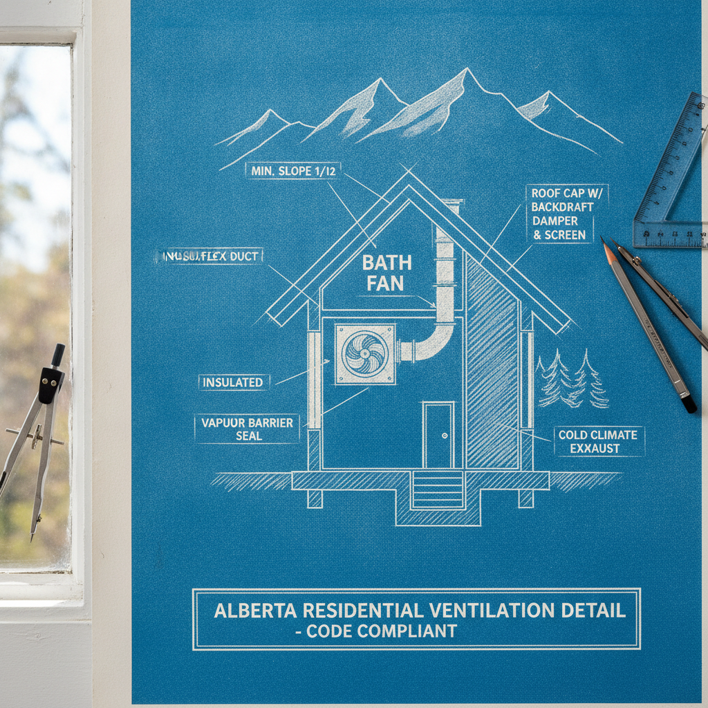
Every bathroom in an Alberta home must be equipped with an exhaust fan ventilation system that directs moist, stale air straight outdoors and away from potential entry points. Meeting or exceeding the latest requirements of the National Building Code - 2023 Alberta Edition (NBC(AE)), which has been enforced since May 2024, architects, drafters, builders, and renovators must pay close attention to the details of fan selection, ducting design, airflow requirements, and exhaust placement. Inadequate ventilation remains one of the primary culprits behind mold growth, premature building material failures, poor indoor air quality, and failed building inspections.
Direct Venting to the Outdoors: The Fundamental Rule
No aspect of bathroom exhaust fan design is more fundamental or more often misunderstood than the requirement for direct outdoor discharge. In Alberta, venting to attics, crawl spaces, wall cavities, or even into soffits without additional measures is strictly prohibited. When exhaust is not sent outdoors, the expelled air-rich in warm moisture and biological contaminants-can condense on framing, insulation, and finishes, creating fertile conditions for mold, rot, and hidden deterioration. Building inspectors routinely cite venting infractions as causes for correction before occupancy or resale.
The most robust architectural drafting practice is to ensure that bathroom exhaust fans are always placed so that duct runs remain as short and direct as possible to an external wall, roof, or specifically detailed soffit termination (with blocking provisions). This approach protects the building’s long-term health and forestalls costly remediation or code violations down the road.
Practical Implications for Renovation and New Construction
- Retrofits: In older homes where code-violating venting into attics or soffits was common practice, careful survey and remediation are required during renovations. Duct rerouting and insulation may be challenging but essential.
- New Builds: Early-stage drafting should always account for direct outdoor venting paths in floor and roof plans. Cross-referencing the fan’s location type (drop ceiling, exterior wall, or main floor interior bath) against wall sections and roof details ensures practical, inspectable compliance.
- Permits and Inspections: Drawing sets submitted for permit must clearly note the direct vent discharge, and not just “vented” or a generic fan symbol. Labeled duct routes and point-of-discharge symbols can prevent confusion for trades and inspectors.
Ductwork Material and Installation: Best Practices and Code Nuances
Fan performance and long-term reliability depend as much on the design and execution of the ductwork as on the fan chosen. NBC(AE) requires that duct interiors be smooth to minimize resistance, which translates in practice to specifying rigid galvanized steel duct for most residential applications. Flexible ducts-acceptable within limits-should be stretched taut to avoid sags, which both accumulate condensation and drastically compromise airflow.
- Rigid vs. Flexible Ducts: Rigid 28- or 30-gauge galvanized steel ducting is the gold standard, specified on many architectural plan sets, because it is durable, smooth, and offers superior airflow performance. Fiberglass-insulated flexible ducts (commonly called “bathroom flex”) may be used for short connections but must be fully stretched, supported, and as straight as possible. PVC or non-rated plastic ducting should never be specified due to code and fire safety considerations.
- Diameter Matching: The duct diameter must match the fan’s outlet. Undersizing leads to backpressure, noise, and condensation. Most residential fans require 4" diameter duct, but higher capacity fans (used for larger bathrooms or quick clear-out) may call for 5", 6", or even larger. Architectural drawings should note these transitions, and specs should be coordinated with mechanical suppliers and site trades.
- Sealing and Joint Detailing: Every duct section and joint must be permanently sealed with foil tape or approved mastic-not general-purpose duct tape, which can degrade over time. Drafters should annotate plans with notes such as “ALL DUCT SEAMS TO BE FOIL-TAPED AIRTIGHT.” Lapse in this step is a common source of unseen bathroom air leaks into building cavities.
Consequences of Poor Duct Selection and Detailing
- Excessive duct friction and poor sealing can reduce fan performance by up to 50% versus manufacturer’s rating, meaning code-required airflow may not be met once installed.
- A duct that is too long, twisted, or narrow increases noise and is more likely to collect moisture on its interior, risking hidden mold and deterioration.
- Thorough, well-annotated drafting is critical: it informs the HVAC contractor, guides inspection, and-when issues arise-provides a clear benchmark for remediation.
Duct Routing: Optimizing for Performance and Inspection
For both renovations and new builds, architectural drawings must show the intended duct path, taking into account framing, insulation, and wiring routes. NBC(AE) requires the layout to adhere to minimal length and maximum airflow principles.
- Straight Runs Preferred: Ductwork should extend straight from the fan for the first three feet, minimizing risk of backflow or turbulence. Including this in sectional drawings and specifying clear headroom avoids later conflicts with truss or joist framing.
- Bend Minimization: Where bends are mandatory, use broad-radius elbows rather than abrupt 90-degree angles. Too many sharp bends ratchet up backpressure, undermining CFM delivery and contributing to fan noise. Marking all bends on plan, with dimensions and maximum allowed, helps the HVAC trade coordinate with framing details.
- Duct Length Calculation: Manufacturers rate fans for a maximum total duct length, typically decreasing with every elbow or directional change. For example, a fan rated for 50 CFM with up to 20 feet of 4" duct may drop to 10-12 effective feet with two 90-degree elbows included. It is prudent drafting to indicate both total length and equivalent length (adding the “penalty” for each bend as per manufacturer data) right on the mechanical plan.
- Fire Stopping and Framing Coordination: For multi-story builds, ductwork passing through fire-rated assemblies must be detailed with proper fire-rated dampers or approved sleeving. Notation on sections or callouts can save hours of remedy work in the field and avoid failed fire inspections.
Insulation and Condensation Control: Building Envelope Integration
In Alberta’s climate, the risk of condensation inside or on ductwork passing through unconditioned space is ever-present. Moisture can permeate insulation, settle on attic framing, or even leak back into bathrooms. NBC(AE) addresses this with clear mandates for duct insulation and fire safety of the insulating material.
- Where Insulation Is Required: Attic and crawl-space duct runs must be insulated to at least the building code minimum (typically R-4 or R-6). In high-performance homes, R-8 or better may be specified, with drawing callouts indicating insulation type, thickness, and vapor barrier application.
- Insulation Detailing: Architectural drawings should specify “Continuous foil-faced or vapor-barrier duct insulation on all unconditioned-space runs,” with overlap at joints. For longer attic runs, even minor gaps can create condensation sites.
- Fire-Rated Insulation: Any duct insulation must meet ASTM C 411 standards (resistance to flame, glow, smoke), which should be noted on specification sheets and in drawing details. Some common insulations are not up to this standard and should be vetted.
- Combining Air Barrier Detailing: Duct insulation must integrate with building envelope air and vapor barriers, especially at attic-floor penetrations. This means coordination between architectural, mechanical, and building envelope drafting teams, typically indicated on larger-section or exploded-detail callouts near every bathroom fan location.
- Drainage Provisions: In high-performance or multi-unit situations, the designer may specify a slight pitch (minimum 1/8"/foot) down toward the outdoor termination, so that any formed condensate drains away from the fan and bathroom, rather than back into the living space.
Consequences of Neglected Insulation Details
- Roof leaks, frost damage, icy attic ducts, hidden attic mold, and water stains in bathrooms all can trace back to under-insulated or poorly integrated vent ductwork.
- Code-compliant insulation, detailed and cross-referenced on the permit plan set, preempts contractor errors and makes inspection straightforward.
Exhaust Outlet Placement: Achieving Code Clearances and Effective Ventilation
The final discharge point of the bathroom exhaust system is as critical as its duct pathway. NBC(AE) dictates strict spatial relationships between exhaust outlets, other building penetrations, and building envelope features to prevent exhaust air from re-entering the building or contaminating air supplies. Failure at this step means the ventilation system does not serve its intended purpose and may compromise indoor air quality throughout the home.
- Clearance Requirement: All exhaust outlets must be located a minimum 1,800 mm (approx. 6 feet) from any air intake (HRV, furnace, fresh-air, or make-up air intakes). This applies both horizontally and vertically. On tightly spaced or infill lots, a detailed exterior elevation or rooftop plan should quantify these clearances and use graphic scales to show compliance.
- Soffit Discharges: Venting through a soffit is permitted only if (a) the soffit is unvented, or (b) if the soffit is vented, the full depth of the vented soffit is blocked off for 1,800 mm (6 feet) each side of the exhaust outlet. This provision-frequently overlooked-should be clearly detailed on architectural sections. Notes such as "Provide continuous solid soffit blocking as per NBC(AE) 9.32.3.9" directly above relevant wall or roof details can prevent costly remediation and failed inspections.
- Wall vs. Roof Terminations: Wall-term executions are sometimes preferable, particularly when roofline complexity or distance from bathroom locations present design challenges. On the wall elevation sheets, show the vent hood location with dimensions from finished grade, eaves, intakes, and windows. Vents must be equipped with a damper to prevent cold air infiltration, and a bird/insect screen to avoid blockages.
Common Pitfalls and Solutions at the Exhaust Outlet
- Poorly documented exhaust outlet locations frequently result in on-site guesswork, which can lead to code violations and air quality issues post-construction.
- In multi-story homes, discharging near deck doors or high-traffic windows can lead to persistent odor complaints. Drafting teams should review exterior features and specify optimal outlet positioning to minimize nuisance.
- Careful coordination with exterior finishes is essential; stone, stucco, or brick cladding may require special vent hoods or extra blocking, all of which should be addressed in drafting notes and sections.
Airflow Requirements: Sizing Fans for Room and Occupancy
Alberta’s NBC(AE) prescribes strict airflow minimums to ensure bathrooms are adequately ventilated under normal use. For intermittent operation (systems that turn on with use and off after), the minimum is 50 CFM. Continuous systems (operating at low speeds 24/7) are allowed at a reduced minimum of 20 CFM. These numbers are not arbitrary-they are matched to moisture and contaminant generation rates in typical residential bathrooms.
- Fan Sizing: Drafting sheets should specify fan CFM and, where required, the calculation method used (“Room volume x air changes per hour” or similar). When in doubt, larger is safer, provided noise is controlled and ductwork is properly matched.
- Multiple Baths: In homes with multiple adjacent bathrooms, zone or manifolded venting is never acceptable unless each bath has its own dedicated fan and run. Shared and “looped” systems fail to meet NBC(AE) and are likely to cause moisture problems.
- Specialty Bathrooms: Oversized baths (with multiple fixtures, spa tubs, or showers) require correspondingly larger fans and sometimes dual units. Plans and schedules should document this and show fan models, capacity, and duct sizes.
- Derating for Duct Losses: All calculations for CFM delivery must take into account real-world deductions for duct length, bends, material, and termination hoods. Architectural notes should read: “Minimum measured exhaust airflow at exterior outlet shall not be less than 50 CFM” and reference the measurement protocol (e.g., airflow hood test at completion).
Mistakes in Fan Sizing: Risk Assessment
- Undersized fans cannot clear moisture rapidly, leading to mirror fogging, residual odors, wall staining, and-over the long term-damp drywall or finish failures.
- Fans sized by “rule of thumb,” without taking into account the as-built ducting, may perform below code minimums even if manufacturer-labeled for the right volume. Field measurements post-construction are the gold standard for validation.
Noise Control: Sone Ratings and User Comfort
Excess fan noise can render a bathroom unpleasant and prompt users to disable fans, defeating the core intent of ventilation. The NBC(AE) addresses this proactively: for continuous operation, a maximum sone rating of 1.0 or less is required; for intermittent operation, up to 3.0 sones is allowed. Sone rating should always be shown on the drafting specification.
- Quiet Fans for Main Baths: Family or master bathrooms intended for frequent use and overnight occupancy benefit from ultra-quiet models, specified on the architectural plan with “Certified Quiet (≤1 sone when continuously operated).”
- Budget Considerations: While higher-end, quieter fans may incur more upfront cost, the long-term benefit in occupant satisfaction and code compliance is significant. Plans should offer alternates (Good/Better/Best), especially in multi-unit or speculative builds.
- Integrated Fan/Light/Heater Assemblies: Complex bathrooms or luxury homes may use combination units, all of which must be listed on the mechanical schedule with airflow, sone, and power supply data for clarity.
- Coordination with Lighting Design: Since fan/light units require specific placements for both functions, ceiling plans and reflection plans should be developed in tandem to avoid conflicts between lighting and vent placement.
Best Practices in Sone Rating Documentation
- Always specify sone rating alongside airflow and model on the plan set; this eliminates interpretation and reduces change order requests for ambiguous “acceptable” fans.
- Fan substitutions by trades should require architect or designer approval to verify sone rating and compliance with other requirements.
Maintenance and Inspection: Ensuring Long-Term Performance
Even the best-designed and code-compliant exhaust systems degrade over time without proper maintenance. Drafters and designers play an important role in facilitating access and providing clear inspection notes that serve homeowners, contractors, and inspectors for the building’s lifespan.
- Accessible Fan Locations: Plans should show access provisions for both fan and duct: removable trims, ceiling hatches, or attic access where in-line or remote fans are used. This allows for regular cleaning and, if needed, repair or replacement post-occupancy.
- Cleanout Points: For long or complex duct runs, especially in custom builds or multi-bath homes, plans may specify inline access or cleanout ports, particularly in attic runs where lint and dust can accumulate unseen.
- Maintenance Note Inclusion: On general notes or mechanical schedules, provide operation and maintenance reminders: “Fan and duct to be inspected and cleaned annually. See O&M manual for procedures.”
- Inspection Checklists: For new construction and renovations, many permit authorities expect inspection checklists to be included or referenced. Drawings can note: “At final inspection, verify direct outdoor discharge, full duct insulation, 1800 mm intake clearance, operable damper, and measured airflow.”
Variance and Alternative Solutions: Navigating Special Situations
Site-specific constraints, such as tight lot lines, existing conditions in renovations, or stacked services in multi-family developments, may make straightforward compliance challenging. In these cases, the NBC(AE) allows for variance submissions and alternative solutions, provided performance-based criteria are met and approved by local regulatory authorities.
- STANDATA 23-BCV-008: This documented variance provides policy on alternative clearances for exhaust outlets near intakes, where standard 1,800 mm separation is physically impossible (such as in dense infill). In these cases, detailed drafting-including airflow modeling and barrier solutions-becomes even more critical. All variance applications should be referenced by number and submission date on the relevant drawings and included in permit applications.
- Custom Envelopes and Enclosures: Some projects may need boxed or channeled terminations, or custom weather hoods, which must be detailed at 1:5 or 1:10 scale to provide clear instruction for site build-out and inspection. Cross-referencing custom details to section callouts avoids field confusion.
- Coordination with Mechanical Engineering: When a specialized mechanical consultant is engaged (common for large or high-end homes), the architectural plan set should reference mechanical drawings for duct routing, sizing, and airflow validation, and mechanical schedules for fan model specifics, ensuring both disciplines are in agreement.
Comprehensive Architectural Drafting Checklist for Bathroom Exhaust Venting
- Location: Position fan as close to moisture sources (shower, tub, toilet) as practical; confirm electrical supply and ceiling type.
- Duct Routing: Show full duct path in plan and section; minimize bends; quantify length and equivalent length; coordinate with other services.
- Duct Material: Specify rigid galvanized duct unless impracticable; show insulation and fire rating notes where duct runs in unconditioned space.
- Termination: Locate outlet at least 6 feet from all intakes, windows, deck doors; detail any required soffit blocking or boxed-out terminations.
- Fan Specification: List model, CFM, sone rating, voltage, control type (switch, timer, occupancy sensor, or humidistat).
- Integration: Indicate coordination with lighting, ceiling joists/trusses, attic baffles, and exterior cladding.
- Airflow Validation: Require post-construction measurement of exhaust at outlet; provide note specifying minimum delivered airflow.
- Variance Documentation: Reference any approved variances directly on sheets and cover letters; provide detail drawings for alternative solutions.
- Maintenance Access: Show access for inspection/cleaning; reference O&M documentation and municipal maintenance schedules.
- Inspection Note: Summarize items for inspection: “Direct vent; airtight duct; full insulation; dampered, screened outlet; airflow test passed.”
Case Study Insights: Applying the NBC(AE) in Practice
Consider a multi-bath suburban infill in Calgary, where bathrooms are positioned on both interior and exterior walls and the attic is a heavily insulated low-slope design. Drafting challenges include:
- Minimizing duct length for main-floor interior baths by stacking mechanical chases and maintaining insulation for long attic runs.
- Locating exterior discharges away from new, high-efficiency HRV intakes without conflicting with windows, eaves, or deck exits.
- Specifying higher-capacity, low-sone fans for master baths with multiple fixtures, coordinating both electrical and lighting layouts to support fan-light operation.
- Detailing soffit blocking on all vented eave runs, including sub-details in sections to preclude site improvisation.
- Preparing and annotating a variance submission for one bath where less than 1,800 mm to an intake could be achieved, specifying a proprietary vent hood with directional discharge and proving no risk of cross-contamination through airflow simulation.
This level of detail in the drafting phase builds confidence in compliance, minimizes calls from site, and results in a healthier, more durable home.
Expert Recommendations for Bathroom Ventilation Drafting
- Start each project by mapping the full bathroom plumbing, electrical, and ventilation layout in plan and reflected ceiling plan (RCP), noting potential duct runs early.
- For multi-story and high-performance homes, work closely with envelope consultants to synchronize insulation, vapor, and airflow barriers across penetrations.
- Annotate every mechanical/ventilation sheet with code references (NBC(AE) sections by number), especially for inspector review and variance scenarios.
- Insist that all key documentation - from manufacturer’s fan specs to insulation fire rating sheets - is included in construction packages and permit submittals.
- Design for maintenance as much as for initial compliance: ensure that future homeowners and service technicians can clean, repair, and test the exhaust system without demolishing finishes or framing.
- Conduct post-construction airflow verification at the exterior vent, not just at the fan face; annotate this requirement on plans and in contract specs.
Summary: Delivering Lasting Results through Careful Drafting
Proper bathroom exhaust fan venting is a nuanced, multi-faceted process, integral to home durability, air quality, and code compliance in Alberta. It depends not just on product selection but on deeply considered drafting: from direct, insulated duct routing to detailed outlet clearance and performance annotations. By leveraging the comprehensive requirements of the National Building Code - 2023 Alberta Edition-and working these details into every drafting set-quality, compliance, and occupant satisfaction are guaranteed.
Through careful attention to every aspect of the bathroom exhaust system’s drafting, Kingsway Drafting & Design ensures architectural excellence and durable comfort in every Alberta home we serve.