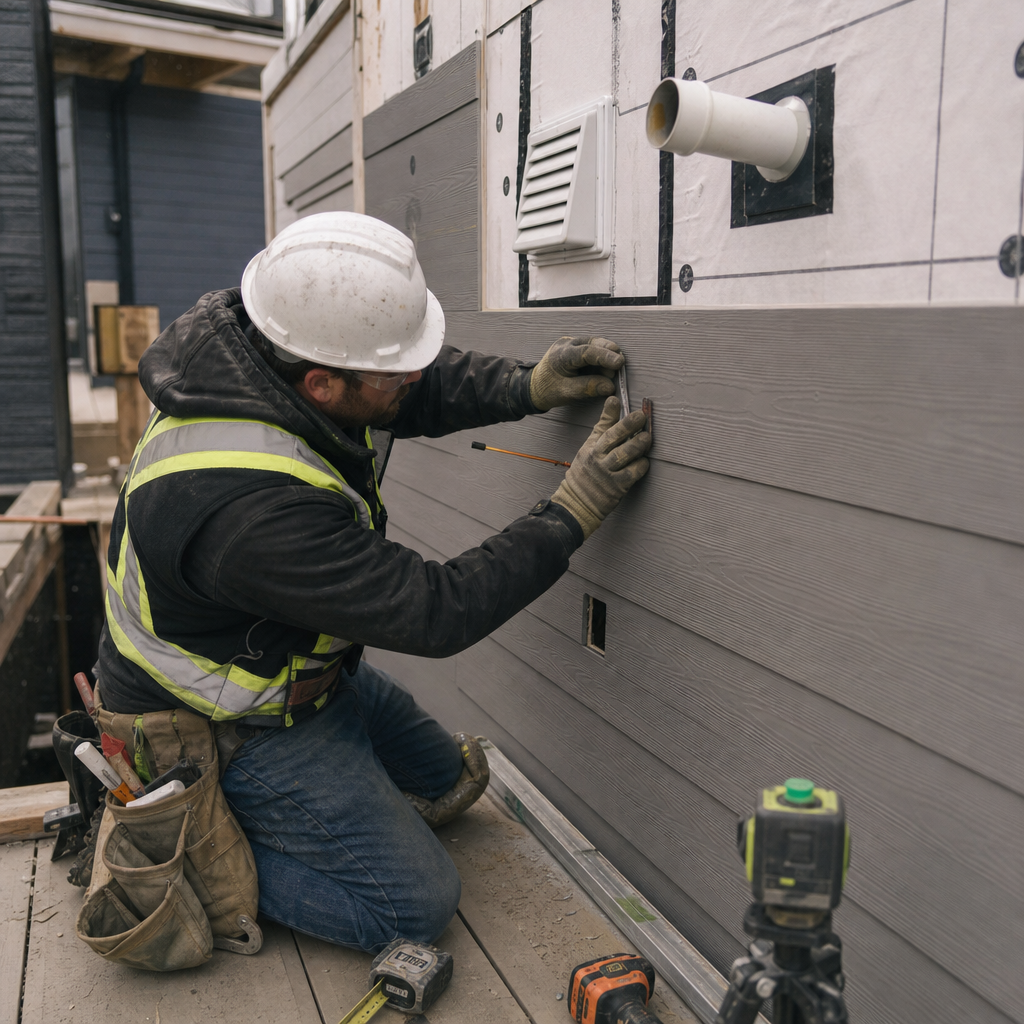
Precise separation between exterior air intakes and exhaust vents is a core compliance and performance requirement on Alberta residential architectural plans. Since May 1, 2024, the National Building Code - 2023 Alberta Edition (NBC(AE)) and its STANDATA variances have strengthened expectations for clear, documented exhaust/intake relationships. Plan sets neglecting these dimensions or omitting material call-outs regularly see time-consuming redlines, project delays, or even permit rejection. Drawing exhaust and intake terminations accurately-dimensioned, specified, and detailed to code-has never been more critical.
Dimensioning to Code: Combustion Air Intakes & Power-Vented Exhausts under ABC 9.32.3.10 & 9.32.3.11
Section References and Their Manifestation on Alberta Plan Sheets
Combustion air intakes and power-vented exhausts for appliances occupy a uniquely regulated position on the architectural sheet set. The NBC(AE) mandates weather protection and separation distances as direct, diagrammatic requirements:
- 9.32.3.10 - Protection from Weather: "Outdoor air intakes and exhaust outlets shall be protected from the weather and from the entry of insects, birds and rodents by the use of hoods incorporating corrosion-resistant screens of not more than 12 mm and not less than 6 mm mesh." Screens must be noted and drawn to section.
- 9.32.3.11 - Ducts: "Ducts that serve ventilation systems shall be constructed of noncombustible material, be installed to prevent air leakage, and insulated to RSI 0.5 for portions passing through unheated spaces." Metal ducting and insulation depth must be specified in the duct legend or in keynote callouts.
On coordinated plan sets, drafter annotations often include:
- Detail references: "SEE DETAIL 4/A5.1-EXTERIOR AIR INTAKE CONFIGURATION"
- Material call-outs adjacent to duct route: "DUCT MATERIAL: NONCOMBUSTIBLE, CORROSION-RESISTANT PER ABC 9.32.3.11(1)"
- Explicit clearance dimensions: Tag lines and dimensions such as "900 mm MIN. HORIZONTAL CLEARANCE TO AIR INTAKE" highlighted in bold or colored overlays
STANDATA Variance 23-BCV-008(REV1): Alberta-Specific Clearances
Alberta's 2024 STANDATA Variance 23-BCV-008(REV1) modifies the separation distances for domestic exhausts:
- 900 mm (36") minimum horizontal clearance between exhaust outlet (e.g., range hood, dryer, bath fan) and the nearest outdoor air intake.
- 1,800 mm (71") minimum vertical clearance when the intake is located above the exhaust outlet.
- 900 mm (36") minimum vertical clearance when the intake is located below the exhaust outlet.
These clearances supersede generic code minimums and MUST be dimensioned on site and detail plans. A common plan-review redline: "Provide clear dimensions indicating the separation between combustion air intakes and exhaust outlets to verify compliance with STANDATA Variance 23-BCV-008(REV1)." Drafters must show both plan-view and elevation-view dimensions, often with "bubble callouts" highlighting the separation.
Material Specification and Weather Protection Details on Drawings
- Hood details: Typical elevation symbol, plus a section ("SEE DETAIL 2/A6.4") showing hoods with annotated mesh (6-12 mm corrosion-resistant screen as per 9.32.3.10). Screens are hatched in detail views, and a note in the door/window/vent schedule clarifies "screen to 9.32.3.10(1)".
- Duct insulation + sealing: Insulated duct symbol shown in mechanical plans; architectural sheet notes: "EXHAUST DUCT INSULATION: RSI 0.5 MIN. (MMFG LABELLED)" and "JOINTS SEALED W/ MASTIC OR FOIL TAPE PER ABC 9.32.3.11(4)".
Redlines from reviewers are often directly actionable: "Specify duct materials in accordance with ABC 9.32.3.11.(1), ensuring noncombustible, corrosion-resistant materials are used for cooking appliance exhaust fans."
Drawing Standardization and Reputable Referencing
Plans referencing ABC section numbers, with clouded call-outs and keyed notes to the legend, help plan examiners quickly validate compliance. Recommended approaches include:
- Legend note: "VENTILATION COMPONENTS TO MEET NBC(AE) 9.32.3.10-11 (SEE DETAILS)"
- Dimension annotation: Dimension lines between exhaust and intake, with text "MIN CLEARANCE PER STANDATA 23-BCV-008(REV1): 900mm HORIZ, 1800mm VERT"
- Tagging vent types: E.g., "COMBUSTION AIR INTAKE (TAG: A1)", "RANGE HOOD EXHAUST (TAG: E1)" referenced in detail index
HRV/ERV System Intake/Exhaust Separation: Precision Detailing for Alberta Homes
Manufacturer-Guideline and Code-Driven Separation on Plan Sets
Heat Recovery Ventilator (HRV) and Energy Recovery Ventilator (ERV) systems present unique drafting challenges. While NBC(AE) 9.32.3.10 details hood and screening requirements, it leaves intake/exhaust spatial separation distances to best practice and manufacturers. Industry-aligned Alberta plans adopt clear rules:
- Minimum 1.83 m (6 ft.) separation between HRV/ERV fresh air intake and its corresponding exhaust air outlet-dimensioned both horizontally and as a slope-adjusted direct line where facades shift in/out.
- Elevation above grade: Minimum 457 mm (18") above finished grade or seasonal high snow-dimensioned in wall-section details and explicitly tagged: "18" MIN ABOVE GRADE TO BOTTOM OF HOOD"
- Intake distance to local contaminants: 3 m (10 ft.) from gas appliance exhausts, idling vehicle areas, or garbage bins. Plans show this dimension from the edge of nearest known contaminant point to the centerline of HRV/ERV intake.
A standard detail block on Alberta plan sets for HRV/ERV terminations will note:
- Screen note: "ALL INTAKE & EXHAUST HOODS FITTED WITH 6-12 MM CORROSION-RESISTANT MESH PER NBC(AE) 9.32.3.10"
- Separation dimension: "HRV INTAKE & EXHAUST-6' (1.83 m) MIN. DIRECT LINE SEPARATION"
- Elevation and grade note: "HRV/ERV INTAKES NOT TO BE OBSTRUCTED BY SNOW (MIN. 457 mm ABOVE MAX SNOW ACCUM.)"
Plan-Review Redlines and How They Show Up in Sheet Changes
- "Intake and exhaust vents are too close; increase separation to minimum 6 feet"-Requires explicit dimension lines on facade/plan views, plus reference in the vent schedule.
- "Vents are positioned below the required 18-inch elevation; adjust placement"-Corrected with elevation benchmarks shown in wall section and on finished grade datum lines.
- "Intake vent located near potential contamination source; relocate"-Plan updates should show all contaminant-producing features, using overlays and explicit measured offsets.
Plan sets with missing or ambiguous vent separation are now routinely flagged, delaying approvals. Clarity up front saves cycles.
Symbols, Material Specs, and Sheet Conventions for HRV/ERV Details
- Symbols: Consistent intake/exhaust blocks, e.g., triangle with an "I" for intake, square with "E" for exhaust, legend-noted.
- Detail callouts: "SEE DETAIL 6/M4.2 FOR HRV VENT TERMINATION"
- Material spec notes: "DUCTS: GALVANIZED 22 GA. STEEL, INSULATED TO R-8 (RSI 1.41) OUTSIDE ENVELOPE, ALL JOINTS FOIL-TAPED PER SMACNA"
Intake/exhaust separation lines and dimensions are drawn in contrasting color or bold weight, with a cross-reference to the full schematic on the mechanical plan. Such cross-sheet referencing is now expected in permit submittals.
Detailing for Code and Performance
Detail views in Alberta plans illustrate the following:
- Hood section with mesh screening, weather shield cap, and specific mounting height.
- Direct-vent path marking, showing shortest direct line between intake and exhaust, annotated as "6' DIRECT MIN."
- External grade annotation, benchmarked for snow, e.g., "INTAKE TERMINATED AT 650 mm ABOVE ELEV. @ SLAB"
Material schedule should reference "HVI-listed termination kits, corrosion-resistant" and ductworks "compliant with SMACNA, 22 ga. galvanized min." Where intumescent coatings or proprietary fire-rated hood assemblies are required due to wall-fire rating (see Site-Specific section), that detail is explicitly noted.
Standard & Non-Standard Exhaust Terminations: Dryer, Range Hood, Bath Fan-Callouts and Code on Alberta Sheets
Code Sections and Alberta Modifications-Dimensioning on Permit Drawings
- ABC 9.32.3.13: "Exhaust outlets that discharge air containing moisture, including bathroom ventilation and clothes dryer exhaust outlets, shall be located at least 1,800 mm (71") from air intakes and vented soffits." This is the baseline dimension required unless variance applies.
- STANDATA 23-BCV-008(REV1):
- 900 mm (36") horizontal separation (can supersede 1,800 mm for certain exhausts/intakes if alternate compliance path is chosen and documented on drawing and in zoning submission)
- 1,800 mm (71") vertical clearance above, 900 mm (36") below exhaust
Drawings often face redlines such as: "Dryer vent discharge is too close to vented soffit; adjust placement to meet ABC 9.32.3.13(4) requirements." To mitigate this, standard detail sheets include:
- Dimension tag: "1,800mm MIN. HORIZONTAL SEPARATION (REF: 9.32.3.13(3))" between exhaust and nearest intake or soffit (or allowed reduction)
- Elevation markers referencing lowest vented soffit portion: "DRYER EXHAUST 1,800mm MIN. CLEAR OF SOFFIT VENT"
Exhaust Route Annotation and Material Specification on Drawings
- Routing lines: Continuous dashed or dotted polyline (legend: "EXHAUST ROUTE"), with start/end labeled (e.g., "BATH FAN EXHAUST TO EXTERIOR WALL-SEE ELEVATION 3/A7.4")
- Termination details: Wall-mounted or roof-mounted terminations shown with keynotes: "DRYER TERMINATION-ROOF, METAL VENT WITH BACKDRAFT DAMPER" or "RANGE HOOD TERMINATION, WALL, 2 m MIN. FROM OPENING/INTAKE"
- Material notes: "ALL DRYER/RANGE/BATH EXHAUST DUCTWORK TO BE 26 GA. MIN. GALVANIZED STEEL, NO PLASTIC OR FLEX DUCT IN CONCEALED SPACES"
- Backdraft damper callout: "PROVIDE BACKDRAFT DAMPER AT TERMINATION"
- Screen callout: "HOOD FITTED WITH 6-12 mm CORROSION-RESISTANT MESH"
On sections, a typical callout is: "TERMINATION 100mm MIN. ABOVE GRADE, SEE DETAIL 5/A8.2". Apex of vent must match grade reference elevation, shown with a continuous datum line.
Plan-Review Feedback and Plan Revision Details
Some common review comments:
- "Exhaust vent termination is located within 1,800 mm of an air intake; relocate."
- "Clothes dryer exhaust is routed through attic/soffit-prohibited. Revise routing."
- "Specify all exhaust materials as noncombustible, corrosion-resistant."
Revisions are typically not limited to the affected plan-keynote updates, cross-references in the vent schedule, and corrected dimension lines in both elevation and site plans are expected for approval.
Navigating Plan Review: Non-Compliance Triggers, Redlines, and Smart Drafting Revisions
Common Triggers for Redlines-and Sheet-Level Fixes
Review cycles for Alberta homes consistently surface certain drawing problems relating to Section 9.32.3.13:
- Lack of explicit 1,800 mm separation dimension between intakes and exhausts.
- Exhaust outlets terminating near vented soffits, with no detail or inadequate distances shown.
- Unclear or missing screen and hood specifications as called out in 9.32.3.10.
- Ambiguous material annotations-often missing "noncombustible" or "corrosion-resistant" designation.
A representative redline: "Provide section view showing 1,800mm clearance between all dryer, range, and bath exhausts and any air intakes or vented soffits per ABC 9.32.3.13(3)-(4)." To correct, the drafter provides a dimensioned section (e.g., "SEE SECT. 2/B8.3") with explicit callouts from termination centerpoint to the nearest soffit/vent.
Drawing Conventions That Prevent Plan Rejection
- Dimension overlays: Use bolder or colored lines on intake/exhaust separation dimensions.
- Detailed notes block: "ALL EXHAUST/INTAKE LOCATIONS TO CONFORM TO NBC(AE) 9.32.3.13/13.1 & STANDATA 23-BCV-008(REV1). SEE DETAILS FOR ALL CLEARANCES."
- Manufacturer data cut sheet cross-references: E.g.: "SEE MFG. SHEET-HRV/ERV INTAKE SPLASH GUARD INSTALLATION"
Where multiple exhausts/intakes are clustered, as on tight urban lots, each individual relationship must be dimensionally explicit-so reviewers need not infer the location or compliance of any vent.
Smart Strategies for Drafting Revisions
- Start with a row-by-row code crosswalk-color code or cloud circles/areas that trigger a code requirement.
- Identify all at-risk vents/intakes (those within 2 m of each other or near prohibited locations like vented soffits/fire-rated walls).
- Revise not only plan/elevation but also coordination diagrams-including mechanical/architectural overlays and legend updates to synchronize all affected views.
- Explicitly note "COMPLIANT TO ..." with current Alberta code amendment/version # in plan legend and general notes.
- Document before/after on revised sheets to expedite plan review and facilitate inspector sign-off on site.
Poorly coordinated revisions-such as dimension changes on plan but not on schedule-are a top reason for second-round review comments. Detailed, consistent, and referenced corrections are essential.
Detailing for Site-Specific Venting: Zero Lot Lines, Rooflines, Grade Changes under Alberta Code
Vent Placement Challenges in Tight and Complex Conditions
Site constraints such as zero lot lines, multi-slope roofs, and substantial grade changes force creative-but still code-bound-vent and intake placement. The NBC(AE) Section 9.32.3.13 mandates exhaust separation from intakes and soffits regardless of how spatially constrained an elevation may be.
- Zero Lot Line: Dryer or bath exhaust cannot be placed less than 1,800 mm horizontally from an intake or vented soffit-even if the opposite façade or party wall is within 1.2 m of the property line. Side yard reductions cannot override exhaust/intake/soffit separation requirements in Section 9.32.3.13.
- Complex Rooflines: Crowded rear and side elevations (hip/valley roofs) can result in soffits spanning grades or bumpouts. Plan drawings must show exhaust paths exiting outside fire-rated soffit assemblies, or, where allowed under STANDATA Variance 19-BCV-017, provide detail callouts such as: "VENTED SOFFIT-INUMESCENT PROTECTED PER STANDATA 19-BCV-017; SEE DETAIL 6/A7.7."
- Grade Changes: Sidewalk-adjacent or step-down lots require dimensioning from finished elevation-not nominal grade. Termination elevation must measure at the point of vent, not slab/walk/retaining wall, and be referenced on the site data block.
Common redline: "Termination elevation is not measured from finish grade; revise to show elevation at vent outlet in context of retaining wall grade change."
Drawing-Set Solutions and Material Specifications for Challenging Sites
- Include a "SITE VENT + INTAKE COORDINATION" diagram, showing all terminations overlaid on the lot, property line, building wall, and grade lines.
- Add detail blocks showing vertical section from exhaust to soffit/intake-even where the wall jogs or steps, to clarify dimension measurement.
- Notation: "NO EXHAUST OR INTAKE TO PENETRATE FIRE-RATED EXTERIOR WALLS UNLESS DETAILED PER VARIANCE 19-BCV-017 (INTUMESCENT COATING DETAIL 3/A9.6)"
- Dimension references must be explicit: "DRYER EXHAUST 1800mm MIN. FROM ANY SOFFIT OR INTAKE, MEASURED HORIZONTALLY @ VENT ELEVATION"
- Where ventless soffits or protected venting are necessitated by firewall, include full spec: "SOFFIT VENT: ALUM. PERFORATED SHEET, INTUMESCENT COAT, FLAME SPREAD < 25; SEE STANDATA 19-BCV-017"
Attic and Roof Venting: Multi-Slope and Small-Area Attics
- Calculate net vent area per NBC(AE): For roofs sloped >1:6, provide min. 1 sq. ft. vent/300 sq. ft. ceiling area-25% low, 25% high.
- Split vents to ensure no vent cluster within 1.5 m of exhaust or intake unless separated by fire-rated baffle (noted with callout, e.g.: "FIRE-RATED SOFFIT BAFFLE, SEE DETAIL 4/A9.3").
- Small attics must provide both low (eave) and high (ridge/gable) vent positions-annotate with dimensioned location and area in square millimeters per code.
Reviewer redlines in these edge cases are often plan-wide:
- "Soffit vents shown within fire separation zone; provide section and intumescent product data per STANDATA 19-BCV-017."
- "Exhaust vent placed on zero-lot-line wall violates code-mandated separation-relocate or provide alternate compliance path and note on plan."
Cross-Sheet Referencing and Submission Best Practices
- All code exceptions (e.g., STANDATA compliance paths) must be clouded and keyed; reference with explicit code section and variance number, e.g., "SEE 9.32.3.13, STANDATA 23-BCV-008(REV1)"
- Nonstandard vent placements require approval block in submission package, with supplementary details provided as Attachment A/B per local authority requirements.
- Legend must indicate which vent locations follow code minimums and which invoke local amendments or manufacturer-specific exceptions.
Full compliance-and a fast review-depend on plan sets that feature dimensioned, referenced, and context-specific details, not just "typical" terminations.
Conclusion: Elevating Alberta Permit Plan Quality through Diligent Intake/Exhaust Detailing
Exterior air intake and exhaust vent placement is not a “tag and forget” drafting task on Alberta residential projects. As the NBC(AE) 2023 and key STANDATA variances have clarified, separation distances, weather- and wildlife-protected terminations, and material specifications must be proactively annotated, dimensioned, and referenced on every permit plan and detail sheet. Plan reviewers expect to see relationships between exhausts, intakes, soffits, and property lines laid out unambiguously-with dimensions both in plan and elevation, section detail keying, cross-sheet referencing, and materials detailed to both code and Alberta-specific amendments.
Systems such as HRV/ERVs, power-vented combustion appliances, range hoods, bathroom fans, and dryer exhausts all demand independent dimensioning-with no two situations code-identical, especially given zero lot lines, complex roof edges, fire-rated walls, and unusual site grades. Code compliance in these areas is not just about referencing NBC(AE) 9.32.3 or rattling off distances-it's about drawing dimension lines, symbol legends, and full material callouts in a way that withstands redline scrutiny and makes on-site installation effortless and error-proof. Coordination across disciplines on the permit set, along with clouded alternate compliance paths where needed, reduces costly revision cycles and keeps approvals on track.
Whether for standard separation or challenging projects, explicit code reference-such as "MIN. 900 mm HORIZ. (STANDATA 23-BCV-008(REV1))," "INSULATED EXHAUST: RSI 0.5 (NBC(AE) 9.32.3.11)," or "VENTED SOFFIT: INTUMESCENT PROTECTION PER 19-BCV-017"-marks the difference between quick approval and prolonged permitting limbo.
Precision in drafting these details remains Kingsway Drafting & Design’s benchmark for excellence in Alberta residential permit plans.