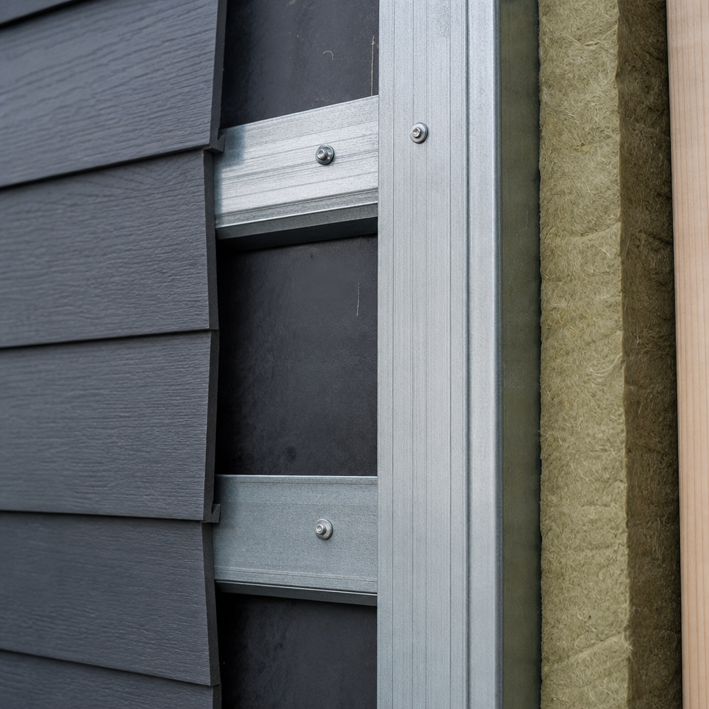
The fastening schedule is a code-mandated permit plan component on every Alberta residential project, essential to both regulatory compliance and on-site clarity. Lenders, permitting authorities, builders, and inspectors alike scrutinize its completeness-not simply as a table of numbers, but as an interlocking network of data fields, code call-outs, and referenced details across the entire drawing set. The Alberta Building Code - 2023 Alberta Edition (NBC(AE)), with its precise Part 9 prescriptive fastening requirements for wall cladding, sets a measured baseline for sheet mechanics, drawing conventions, and specification language. A fastening schedule lacking depth, cross-referencing, or consistency risks immediate plan-review redline, Q-mark, or outright permit rejection. Meticulous drafting methodology transforms a code citation into a reliable construction instruction-especially for typical materials like fibre cement, vinyl siding, and stucco, as well as in challenging edge cases at corners and high-exposure zones.
Deconstructing the Fastening Schedule: Data, Mechanics, and Sheet Placement in Alberta Permit Drawings
Essential Data Fields: Building Element, Fastener Specification, and Spacing
Alberta permit drawings require the fastening schedule to offer a granular map of construction intent, not mere generalizations. Obvious gaps-such as specifying "nails" without type or size, or omitting on-center spacing-regularly draw review comments like, "Insufficient fastener details for cladding," or "Missing information on fastener types, sizes, or spacing." Every fastening line item must combine:
- Building Element Description: A precise label-e.g. "Fibre cement panel to wood stud," "Stucco lath to OSB sheathing," or "Trim board at window/door head." Avoid genericities like "Wall cladding fasteners."
- Fastener Type & Size: For instance, "16d common nail, 3.5” x 0.162” diameter," "No. 8 stainless steel screw, 64 mm long," or "1.98 mm x 38 mm galvanized staple."
- Fastener Spacing & Location: Expressed in both numeric and text form-such as "150 mm o.c. at edges" or "Fixed to framing @ 600 mm maximum." Location should also indicate end-nailing, field-nailing, edge or intermediate support as relevant.
- Material & Coating: Typically "hot-dip galvanized," "stainless steel," or as dictated by code. Omission of "corrosion-resistant" is a common redline on exteriors.
Drawing Mechanics: Table Design, Notes, and Detail Placement
Plans that isolate fastening schedules in a dedicated structural schedule sheet (commonly S-500, S-501, or as part of general notes on A-001) streamline both plan review and job site referencing. The schedule should appear:
- Structured as a Table: Columns for element, fastener specification, spacing, and notes yield clear readability. Example structure:
- Cladding Type: Fibre Cement Panel
- Fastener: 8d Galv. Nail, 51 mm
- Spacing: 150 mm o.c. edges; 300 mm o.c. field
- Substrate: Direct to 38x89 wood stud @ 400 mm o.c.
- Cross-referenced Detail Markers: E.g., "See Detail 2/S-501" links table to drafted section or transition.
- General Notes for Global Application: For example, "All exterior fasteners to be corrosion-resistant per NBC(AE) 9.27.5.1."
- Legend and Symbols: Abbreviations, hatchings, and fastener icons explained to avoid on-site confusion-e.g., "●= Galvanized nail; ▼=Screw," aligns all drawing sheets’ detail conventions.
Standardization for Clarity in Plan Review
Disorganized, inconsistent, or contextless fastening call-outs routinely generate reviewer redlines such as "Non-compliance with code requirements," or "Inconsistent or unclear notations across S-series and A-series sheets." Consistency is paramount. Fastening language, abbreviations, and sequencing should be religiously repeated between table schedules, wall sections, detail blowups, and notes. This enables “plan set navigation” for both reviewers and site superintendents-“Detail 3/S-501: All cladding nails to be 51 mm (2”) galvanized spiral, spaced 150 mm o.c. at panel edges” must unequivocally match the tabular schedule line for “Fibre Cement Siding.”
Critical Code Citations and Local Amendments
Failure to cite the precise current code exposes drafters to comments like, "Incorrect code reference; update to NBC(AE) 2023, Article 9.27.5.4." Alberta adopts the National Building Code - 2023 Alberta Edition; relevant fastening provisions appear under:
- 9.23.3.5 & 9.23.3.6: Fastening and minimum nailing in wood framing.
- 9.27.5.1 & 9.27.5.4: General and specific size/spacing for cladding fasteners.
- Local STANDATA bulletins: Always confirm recent interpretations at alberta.ca/building-standata.
Default Fastener Dimensions and Ratings
Specificity at the table saves costly RFI cycles. E.g., "16d common nail (3.5” x 0.162” diameter)" or "Minimum 32 mm penetration into studs per 9.27.5.4" leaves no doubt for review or on-site inspection. Fastener material must be specified, typically “galvanized steel” or “stainless steel” per code for all exteriors.
Part 9 Prescriptive Fastening Requirements: Translating NBC(AE) Code to Siding, Lath, and Cladding Specifications
Fibre Cement Siding: Panel and Sheet-Type Attachment
Section 9.27.5.4, Table A of NBC(AE) defines attachment for panel or sheet-type cladding-fibre cement among them. Fasteners must engage framing, furring, or solid blocking. Prescriptive minimums:
- Nail Length: 51 mm (2”) minimum
- Spacing: 150 mm (6”) o.c. at panel edges, 300 mm (12”) o.c. at intermediate supports
- Material: Corrosion-resistant; explicitly, “galvanized steel” or approved equivalent
- Example Call-Out: “Fibre cement cladding to be fixed with 51 mm (2”) hot-dipped galvanized nails @ 150 mm (6”) o.c. edges, 300 mm (12”) o.c. field, nailed into framing (38x89 @ 400 mm o.c.). All fasteners to be corrosion-resistant. Ref: NBC(AE) 9.27.5.4."
Vinyl Siding: Fastener Placement for Expansion
Vinyl siding, including insulated types, requires accommodation for thermal movement. Section 9.27.5.4 prescribes:
- Attachment: Direct to minimum 12.5 mm (1/2") plywood or OSB, or 14.3 mm (9/16") lumber sheathing
- Fastener Penetration: Minimum 32 mm (1 1/4”) into framing
- Fastener Location: Center fasteners in nail slots of the hem to permit movement. Never overdrive.
- Example Note: “Vinyl siding to be attached with 32 mm (1 1/4”) min. corrosion-resistant nails per NBC(AE) Table 9.27.5.4, installed in slot center for expansion/contraction. Substrate to be plywood/OSB min. 12.5 mm thick.”
Stucco Lath: Vertical and Horizontal Fastening Regimes
For stucco, fastening details govern both durability and inspection signoff. Per Table 9.27.5.4 and related code text:
- Nails: 3.2 mm (1/8”) diameter, 11.1 mm (7/16”) head, penetration min. 25 mm (1”) into framing or full depth of sheathing
- Staples: 1.98 mm (0.078”) min. thickness; 38 mm (1 1/2”) min. penetration on horizontal surfaces
- Spacing: On framing max. 150 mm (6”) o.c. vertical, 400 mm (16”) o.c. horizontal, with alternates for wider framing spacing noted in code
- Example Fastening Table Entry:
- Cladding: Stucco lath (vertical)
- Fastener: 3.2 mm ø galv. nails
- Spacing: 150 mm o.c. vertical, 400 mm o.c. horizontal
- Substrate: 38x89 SPF framing @ 400 mm o.c.
- Notes: Penetrate full sheathing depth. NBC(AE) 9.27.5.4 and Table A.
Plan-Review Traps: Penetration, Corrosion Resistance, and Thermal Movement
Redline comments frequently flag missing penetration data ("Insufficient fastener penetration detail at OSB sheathing-see 9.27.5.4"), lack of corrosion-resistance call-outs, and failure to permit expansion in vinyl siding nailing. Drafters must explicitly state, “All exterior fasteners shall be galvanized steel; no aluminum permitted in stucco applications; all vinyl siding fasteners centered in nail slots (to permit expansion/contraction per 9.27.5.4).”
Beyond the Table: Integrating Fastening Specifications into Wall Sections, Flashing Details, and Critical Junctions
Wall Sections: Fastener Call-Outs and Dimensioned Overlaps
A table is not self-sufficient; reviewers expect integration into wall sections and enlarged details. For example, a wall section at masonry ledge or window head must show:
- "51 mm (2”) galvanized spiral nails @ 150 mm o.c. at panel edges, 300 mm o.c. field" arrowed to cladding courses
- Dimension lines indicating "38 mm overlap at horizontal joint," and clearly labeled substrate fastener targets ("Into 38x89 SPF stud")
Plan reviewers routinely circle section details that lack these numerical fields, writing, "Add fastener size, spacing, and substrate for cladding in section details."
Flashing and Water-Resistive Barrier (WRB) Coordination
Section 9.27.3.8 mandates flashing at all horizontal cladding junctions and substrate transitions. Fastening of flashings is to be referenced in both wall sections and accompanied by code-dimensioned detail call-outs:
- "Metal flashing (0.33 mm [26 ga.] galvanized steel) to extend 50 mm up behind WRB, 10 mm downward overlap, 5 mm min. drip projection. Fasten with 25 mm galv. roofing nails @ 200 mm o.c., heads sealed beneath membrane, per NBC(AE) 9.27.3.8."
- End-dams at all terminations: "25 mm min. end-dam at all window head flashings. See Detail 4/S-601."
Careless or vague flashing details ("Install metal flashing at window head as per typical") risk redline: "Show min. upward extension and end-dam. See code 9.27.3.8."
Junctions at Openings: Connection to Fenestration, Lintel, and Intermediate Supports
At openings, minimum code fastening must be augmented by manufacturer’s instructions for trims, corner boards, and joiners. E.g., at a window head, the section might read:
- "Trim board (38x140) at window: fasten with 64 mm galv. casing nails @ 400 mm o.c., staggered, min. 32 mm penetration into jack stud."
- "All flashings to be continuous, turned up 50 mm behind WRB, end-dams 25 mm high. All fasteners sealed beneath self-adhered flashing membrane."
Transition details-such as cladding returns into a vertical inside corner or abutment to masonry-must similarly receive explicit fastener and spacing annotation, with references to table schedule line items. Omission leads to review comments: "Provide fastening detail for trim at openings per code and manufacturer spec."
Addressing Edge Cases: Corners, Fenestrations, and High-Exposure Zone Fastening
Zone-Specific Fastener Density and Wind Uplift Adjustments
Alberta’s climate and code place special scrutiny on cladding fasteners at zones exposed to higher wind loads-corners, soffit returns, window reveals, and parapet details. NBC(AE) 9.27.5.4 and associated wind tables prescribe increased requirements in these locations, especially where 1-in-50 hourly wind pressure (HWP) equals/exceeds 0.8 kPa. In regions with HWP ≥1.2 kPa, Part 4 engineering is triggered, and standard tables must be overridden by structural schedules specific to site conditions.
- At corners and edges: "Double-nail all vertical joints in fibre cement siding with 51 mm galv. nails @ 100 mm o.c. max, starting 50 mm from finished corner."
- At corner boards: "Corner trim (38x140) to be fixed with two 82 mm galv. screws, spaced vertically at 400 mm o.c., minimum 32 mm penetration into blocking. All fasteners to comply with NBC(AE) 9.27.5.4 and wind pressure adjustment per site exposure classification."
- At window/door jambs/heads: Manufacturer’s fastening schedule for trims, nailing fins, and returns supersedes generic schedule, and must be called out: "Use window manufacturer-specified pan head screws @ 200 mm o.c. for flanged windows; steel lintel anchors per tested system for masonry surround."
ICF and Non-Standard Substrates
Application of cladding to Insulating Concrete Form (ICF) walls-common in energy-efficient Alberta homes-invokes Table 9.27.5.4-B and mandates direct screw attachment to embedded fastening webs. Typical call-out: "Wood trim over flat ICF: No. 10 galv. screws, min. 3.5 mm Ø, length per cladding thickness, spaced at 400 mm o.c. horizontally into ICF web tabs. Consult Table 9.27.5.4-B for region wind pressure limits." Omission of ICF-compatible detail almost always results in Q-mark or reviewer note: "Provide fastener spec and spacing for ICF substrate per Table 9.27.5.4-B."
Flashing and Transition Resilience
In high-exposure areas, fastener type for flashing is scrutinized for uplift resistance: "Starter flashing to be fixed with No. 8 self-sealing screws, grommeted, @ 150 mm o.c. at eaves and exposed parapets. All edges sealed with compatible elastomeric caulk." Advanced reviews address not only the fastening itself, but the secondary waterproofing integrity inherent in the detail layout.
Mastering Plan Review: Identifying and Resolving Redlines on Alberta Cladding Fastening Schedules
Typical Review Comments and Redline Triggers
- Missing Fastener Data: “Fastener spacing for horizontal wood siding not specified; provide details per NBC(AE) 9.27.5.4.”
- Incorrect Code Citation: “Outdated code reference; use NBC(AE) 2023 Article 9.27.5.4.”
- Inadequate Transition Detail: “No fastener schedule for trim at window/door. Show specific size, spacing, and substrate anchorage.”
- Drawing Set Inconsistencies: “Inconsistent fastening details between S-502 and A-503; ensure uniformity as per NBC(AE) 2023.”
Resolving Redlines: Best Practices and Consistency Across Sheets
- Global Fastener Notes: State, “All exterior cladding fasteners to comply with NBC(AE) 2023 Articles 9.27.5.1 and 9.27.5.4. All fasteners to be corrosion-resistant. Unless otherwise noted, nail size min. 51 mm for wood substrates.”
- Detail Reference System: “See Detail 4/S-601 for corner trim fasteners. Schedule line 7 in table applies.”
- Drawing Set Coordination: Cross-check all details, sections, and schedules. Schedules must reflect the language, sizing, and referencing of detail call-outs-eg. nail length in section equals table and vice versa.
- Use of Legends and Abbreviations: On first schedule page and as repeated footnote, “Galv. = hot-dip galvanized; o.c. = on center; WD = wood.”
- STANDATA and Manufacturer Specs: Where conflicts arise, cite manufacturer instructions (for windows, siding, etc.) or STANDATA for local code variance. E.g. “Where manufacturer’s schedule is stricter than code, use manufacturer’s.”
Material and Dimension Clarity in Submittal
Plan reviewers demand specificity at all junctures:
- Nails for wood siding: “51 mm long, corrosion-resistant, spaced 600 mm o.c. max per NBC(AE) 9.27.5.4.”
- Screws for ICF: “3.5 mm Ø, min. 38 mm penetration to web, 400 mm o.c. horizontal.”
- Flashings: “Galvanized steel, min. 0.33 mm, extend 50 mm up behind WRB, 10 mm min. downward drip. All fasteners with sealed heads under WRB.”
Every plan must explicitly specify both material and code-compliant dimension, never leaving interpretation to the construction phase-this achieves true detail-level clarity.
Drawing Sheet Conventions That Withstand Scrutiny
- Legible table format with references: Not “see schedule per typical.” Instead, “See Fastening Schedule, Table 1/S-500, and Details 2/S-501, 4/S-601 for all exterior cladding.”
- Annotated wall sections: Every detail blowup should have direct arrows to fasteners with type, length, and spacing specified, and substrate indicated.
- Annotations referencing specific code: "Nails as per NBC(AE) 9.27.5.4, table note 2, unless manufacturer requires otherwise."
Conclusion: Achieving Code-Compliant Fastening Schedules for Alberta Cladding
Code-compliant fastening schedules are multifaceted instruments embedded throughout the architectural permit drawing set-laying out not only tabled data, but dimensioned section annotations, flashing/junction details, and zone-specific fastener density to withstand both reviewer scrutiny and the realities of Alberta’s climate. Every field, specification, and cross-reference matters: fastener length, material, spacing, and location, adapted for substrate (timber, ICF, or steel), exposure (edge, corner, high wind), and transition (flashing, fenestration, or trim). Meticulous referencing of NBC(AE) 2023 Articles 9.27.5.1, 9.27.5.4, related manufacturer specs, and STANDATA amendments prevents costly Q-marks, redlines, and on-site confusion-while supporting builder accountability and durable envelope performance. Detailed, standardized fastening schedules, integrated through all relevant sheets and details with dimensional, material, and code precision, are a hallmark of high-performance Alberta residential drafting. Every Kingsway Drafting & Design permit plan embodies this commitment to thorough, review-proof documentation.