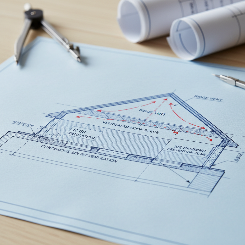
Alberta’s winter climate, marked by sub-zero temperatures and heavy snowfall, creates prime conditions for the formation of ice dams on home roofs. When snow accumulates and the roof deck warms above freezing, due to heat transfer from the building below, meltwater runs down to the cold eaves and refreezes. This ice often forms a ridge or “dam” which traps subsequent meltwater. Lacking proper pathways to drain, the water migrates beneath shingles and underlayment, eventually penetrating the building envelope. Each cycle of melting and refreezing magnifies the risk, turning a modest roofing flaw into a major issue over time.
Sequence of Ice Dam Formation
- Initial Snow Accumulation: Builds an insulating layer over the heated attics and roof decks. The deeper the snow, the greater its insulative effect, accentuating temperature disparities between the deck and the exterior environment.
- Upward Heat Flow: Escapes into the attic due to insufficient insulation, poor air sealing, or both. The rising heat warms the roof-from the interior-starting the melting process on the upper slopes.
- Refreezing at Eaves: Meltwater flows down the slope until reaching the unheated eaves, where it refreezes and accumulates. Over weeks or months, this ice extends both upward onto the roof and downward into gutters.
- Backed-up Water: The resulting ice dam halts drainage, enabling water to back up beneath shingles, wriggle through underlayment, and find any available passage into the attic or exterior wall cavity.
Case Study: Typical Alberta Bungalow
A common mid-century Calgary bungalow, with continuous soffits and a moderately pitched asphalt shingle roof, demonstrates these vulnerabilities acutely. Attic insulation, commonly insufficient by modern R-value standards, sags or compresses over time, especially after DIY upgrades. Numerous ceiling penetrations-old recessed lights, poorly sealed vents, and original plumbing stacks-often go unaddressed after renovation, compounding attic temperature imbalances. The result: visible water stains just inside exterior walls by February, paint bubbles, and eventual interior plaster degradation.
The Cost of Ice Damming: Structural and Health Risks
Ice damming effects are neither subtle nor isolated. Water infiltration driven by ice damming affects both the shell and the guts of a home.
Roofing System Degradation
- Rotting Decking: Persistent moisture under shingles fosters the growth of fungi and accelerates the decay of wood deck sheathing. After a few years of exposure, decking panels delaminate and lose their structural strength.
- Shingle Ruin: Asphalt shingles, especially those at eaves, can curl, blister, or wash out granules. Premature roof replacement becomes inevitable, far ahead of the typical 25- to 50-year lifespan.
- Corroded Fasteners: Roofing nails and flashing are compromised as constant wetting cycles promote rust. Ice expands in cracks and pinholes, opening new fissures for the next thaw.
Interior and Envelope Damages
- Ceiling and Wall Staining: Meltwater finds the least resistant pathways-typically settling above drywall joints and window headers. Brown stains and bubbling paint are early warning signs but signal larger structural risk.
- Mould Growth: Moisture in insulation and cavities fosters mould almost immediately, especially given the intermittent warmth of the attic. Once begun, mould spreads rapidly, hidden by finished surfaces, and can lead to health concerns for building occupants.
- Damaged Insulation: Blown-in cellulose or fiberglass batt insulation loses performance when wet. Its R-value plummets as air pockets fill with water, and drying out without removal is rare in our sustained cold climate. Insulating materials may need to be removed and replaced-a cost and access challenge, particularly in densely filled attics.
- Compromised Air Barriers: Persistent moisture deteriorates polyethylene and other air barrier membranes, undermining the integrity of the building envelope and allowing more warm air to reach the roof deck.
Drafting for Prevention: Best Practices and Code-Compliant Detailing
Precision drafting is pivotal to ice dam mitigation, particularly when plans must comply with NBC(AE) 2023 and incorporate modern construction science. Each step-in insulation, ventilation, and air sealing-must be detailed exhaustively in the construction documentation, so that site execution leaves nothing to chance.
Attic Insulation: Key Principles and Drafting Recommendations
- Minimum Effective Thermal Resistance (RSI 10.43 / R-60 Equivalent): In Alberta’s climate, achieving this insulation value for attic floor assemblies is non-negotiable (as per NBC(AE) 2023). High-performance batts or blown-in insulation, and in certain cases, spray polyurethane foam, are common approaches.
- Full and Continuous Layer: Gaps, voids, or compressed areas invite heat leakage. Every attic obstruction-truss chords, electrical junctions, duct drops-requires custom detailing so the insulation layer remains deep and unbroken throughout, with minimum practical thickness.
- Protecting Insulation from Moisture: Water ingress from above or humid air from below both threaten insulation performance. Detailing must show the placement and specification of continuous vapor barriers on the warm-in-winter side, and note the treatment at penetrations.
- Prevention of Insulation Compression at Eaves: Where the roof slope meets the exterior wall, insulation can thin out or get squashed by low rooflines. Drafting must call for insulation baffles (rafter vents) to maintain both free airflow and full insulation depth-typically showing their size and placement on detail sections.
- Insulating Attic Access Points: Attic hatches or pull-down stairs are notorious for poor sealing and thin insulation. Drawings should feature upgraded insulated hatches with robust weatherstripping, specifying minimum R-values and sealing hardware.
Code-Compliant Insulation: Detailing for Contractors
- Material Type and R-Value Callouts: Notations on plans should identify the exact insulation material and specify the required or recommended R-value by zone, not just generically label “insulation.” This guides procurement and on-site verification.
- Section Details: Cross-sectional drawings should emphasize the full insulation thickness, particularly at eaves, and clarify the integration of vapor barriers and air barriers. Increased callouts and enlarged details at these vulnerable intersections improve trade coordination and minimize field improvisation.
- Schedule of Penetrations: Creating a table or legend identifying all attic penetrations-wiring, vents, stacks-ensures every one is flagged for on-site attention, not only major HVAC or plumbing routes.
Practical Drafting Tip: Staged Construction Notes
Including a construction sequence note set-detailing how insulation, baffles, vapor barrier, and finishes are to be layered and inspected-increases the likelihood that as-built results match the drafted intent. For example, attic insulation contractors may be directed to coordinate with electricians on insulation clearance around warm fixtures or specify rated covers for pot lights to allow full insulation coverage directly overtop.
Attic Ventilation: Engineering Uniform Temperature and Dryness
Roof space ventilation is a critical equalizer, dispersing localized heat buildup and exhausting moist air before it can condense or drive ice dams. The design and drafting of these systems demand attention to local code requirements, attic volume, and roof geometry.
Ventilation Code Requirements and Drafting Solutions
- Ventilation Rate: A minimum net free ventilation area (NFVA) of 1/300 the attic floor area is the Alberta baseline. Larger attics or roofs with obstructions (e.g., cathedral ceilings, added dormers) often require higher rates. Both intake and exhaust must be balanced for pressure-neutral ventilation.
- Intake Vents (Soffit Vents): Located at the cooler, low points along the eaves, intake vents admit outside air which then flows up under the roof decking. Drafted plans should indicate the precise number, location, and NFVA of each vent, ensuring even distribution across the long and short sides of the house.
- Exhaust Vents (Ridge, Roof, or Gable Vents): Located at or near the vertical apex of the attic, exhaust vents permit rising warm air to exit. For optimum crossflow, layout drawings show both ridge venting (continuous) and supplemental box vents in larger or complicated attics.
- Baffles and Vent Chutes: These are critical at eaves to ensure that insulation does not clog intake air paths. Drafting should diagram the baffle width, material, fastener type, and how they interact with truss or rafter spacing. Baffle details should be cross-referenced throughout the roof plan, especially at valleys or intersecting slopes that complicate attic airflow.
- Obstruction-Free Paths: All vents-intake or exhaust-must remain clear of insulation and debris. Section drawings commonly show an air pathway spanning from soffit to ridge for every framing bay, annotated with minimum clearances. Construction notes can reinforce the need for site inspection after insulation placement to spot any blocked baffles or covered vents.
Ventilation Upgrades for Alberta Homes: Real-World Scenarios
- Retrofitting Soffit Vents: Many pre-1970s homes lack sufficient or any soffit venting. Drafting for renovations should include saw-cut locations for new vent installations, detailing how their integration will bypass existing insulation and framing anomalies.
- Adapting to Complex Rooflines: Multi-pitch roofs or homes with a blend of hip and gable features often suffer from attic ‘dead spots,’ where air is stagnant and heat collects. Drafted plans must map secondary exhaust (gable or mechanical powered vents) in these areas, showing both electrical wiring routes and controls.
- Combining Exhaust Types: Sometimes both ridge vents and box vents appear together-despite some manufacturers cautioning against mixing-because Alberta’s freeze-thaw patterns and snow depth demand redundancy. Drafting should justify such combinations with airflow calculations and notes on preferred venting order (i.e., ensuring continuous ridge vents as primary flow paths, with box vents as backup).
Inspection Notes for Contractors
- Vent Space Measurement: Construction notes should instruct that insulating material installer and ventilation contractor jointly sign off that the minimum free air pathway, as drafted, has been maintained after all work. This step can prevent accidental over-stuffing of eaves.
- Pre-drywall Site Reviews: Encourage project managers to confirm attic air pathways are clear, unobstructed by insulation, prior to closing ceilings. Photos, measurements, or a sign-off sheet on major projects help enforce this check.
Air Sealing: Stopping Heat and Moisture at the Source
Even the best insulation and ventilation systems can be undermined by unaddressed air leaks. Uncontrolled warm air escaping into the attic carries humidity, which condenses on cold surfaces and directly warms roof decks, setting up the conditions for ice damming.
Identifying Frequent Leakage Hotspots
- Ceiling-Mounted Light Fixtures: Pot lights often lack insulation-compatible thermal covers in older homes, leaving large gaps through which warm air escapes. Updated drafting should specify airtight, IC-rated fixtures or the use of thermal barrier boxes, shown in section details.
- Attic Accesses: Draft details for hatches, scuttle holes, or pull-down stairs-including rigid insulation layers and proper weatherstripping around the entire perimeter. Sectional perspectives and enlarged plans highlight double-layered air sealing (sealant under hatch stops and compressible gasket at lid contact points).
- Mechanical and Plumbing Stacks: Gaps left between rough openings and pipe or duct penetrations are a major route for exfiltration. Drafting should call for high-temperature caulking or spray foam and include closure details for code-required clearances to combustibles (i.e., around B-vent gas appliances and chimneys).
- Top Plates and Partition Walls: Any interior wall that meets the attic floor can leak conditioned air if not properly foamed or caulked before insulation placement. Drafting should utilize wall-to-attic intersection details, emphasizing continuous air barrier alignment across changes in plane.
Specifying Air Sealing Techniques on Drawings
- Material Notation: Identify approved air-sealant types-acoustic caulk, polyurethane foam, or fire-rated sealants-according to the location and adjacent materials. This prevents field substitutions that may not adhere or interact well.
- Continuous Air Barrier System: Sketch out the path of the air barrier (often 6 mil polyethylene membrane) on plans and reflected ceiling details, including lapping, taping, and sealing requirements at seams, penetrations, and service chases.
- Legend of Penetrations: On large or intricate plans, maintain an indexed list or color-code scheme to flag every required air sealing intervention for building inspectors or project managers.
- Pre-insulation Inspection Point: Add clear milestones in construction schedules for staged air leakage testing (using construction blower doors, if possible) so major failures are discovered before insulation and drywall are installed, not after.
Compliant Detailing: NBC(AE) 2023 Requirements in Focus
The NBC(AE) 2023 prescribes specific requirements for Alberta homes-many directly targeting the causes of ice damming. Drafting must translate these articles into actionable details.
Thermal Resistance and Barriers
- Article 9.36.2.6. (RSI 10.43): Ceilings below attics must have at least RSI 10.43 effective thermal resistance. Section details must call out full depth and coverage at every location, including eaves, valleys, and intersection points with dormers or skylights.
- Vapor Barriers: Polyethylene (6 mil, minimum) over all conditioned ceiling areas. Detailing should specify overlap, tape type, and order of application relative to insulation and drywall for airtightness and inspection.
Continuous Air Barrier Systems
- Article 9.25.3.1.: Requires a continuous air barrier system separating conditioned spaces from roof and wall cavities. Drafted plans need to show this layer on all relevant plan, section, and detail sheets, highlighting transition locations where trades may typically fail, such as at mechanical penetrations.
- Ceiling-to-wall Transitions: Enlarged details at truss chords, especially above complex framing or multi-level spaces, clarify for trades how the air barrier connects horizontally and vertically across volumes.
Attic and Roof Ventilation
- Article 9.19.1.1.: Mandates roof space ventilation for moisture control; drafted plans must provide calculated vent areas on schedules, symbol keys for all intake/exhaust locations, and section drawings clarifying intended air flow paths.
- Details for Special Conditions: Complex intersections, such as shed-to-main roof junctions or overframed dormers, require enlarged coordination details to highlight how ventilation will not be compromised by unique geometry.
Detailed Drafting Techniques for Ice Dam Prevention
Success in ice dam prevention comes not from generic drawing notes, but from finely tuned details and comprehensive architectural drawing sets.
Sectional and Detail Drawings
- Typical Eave/Attic Detail: Shows the interaction between wall top plate, blown-in insulation, insulation baffle, soffit intake vent, exterior cladding, vapor barrier, air barrier, and attic vent chute. Critical dimensions (e.g., insulation thickness, baffle air space, distance from eave to beginning of full-depth insulation) must be referenced.
- Attic Hatch Detail: Enlarged drawings illustrate a multi-layered approach-hatch insulated to match attic R-value, double gasketed, and air sealed on all four sides.
- Mechanical/Electrical Penetration Detail: Diagrams show both code-required clearances for fire safety and specified air sealing with foam, caulk, or sheet metal escutcheons, depending on element type.
- Ridge Vent Section: Shows exact sheathing cutout, nailing schedule, vent profile, and integration under the ridge cap shingles to ensure longevity and avoid wind-driven water intrusion.
Schedules and Legends
- Ventilation Schedule: Table listing all intake and exhaust vent products, their net free ventilating area (NFVA), and their specific installation location or spacing. This prevents under-ventilation or installation error.
- Insulation Type Schedule: Specifies not only the material but also the delivery and installation method (e.g., loose-blown fiberglass, dense-packed cellulose, rigid foam, spray foam at transitions), with performance notes about minimum settled thickness.
- Air Barrier Penetration Index: Prints a running list of all planned or possible penetrations, tagged to drawing callouts, so that none are accidentally omitted during design changes or site modifications.
Construction Note Integration
- Special Instructions for Contractors: Boxed callouts in key locations advise on how to coordinate overlapping work, such as having one trade install baffles before another spray foams, or requiring pictures of clear soffit paths before insulation blow-in commences.
- Verification and Sign-Offs: In high-performance or Builder's Warranty projects, plans may request third-party inspections or builder checklists for insulation depth, vent pathway integrity, and continuous air barrier completion before drywall hang, reducing risk for owners and trades alike.
Practical Construction Implications: Lessons from Alberta Projects
Real-world construction outcomes in Alberta distill theoretical best practice into hard-earned lessons. Many issues arise not from a lack of intent but from ambiguities or missing detail in documentation.
Failure Point: Incomplete Attic Air Barriers
In multi-phased housing developments, air barrier continuity often breaks down at transitions-such as party wall tops or intersection of trusses with sloping ceilings. Without clear section details, trades may staple, tuck, or simply cut away vapor and air barrier membranes. Including double-redundant air barrier linework and cross-reference notes on all affected pages sharply reduces this risk.
Failure Point: Insufficient Venting Due to Over-Insulation
When contractors blow in cellulose to the specified R-value, it’s common for installers to partially (or fully) block vent chutes at the eaves-or miss baffle installation altogether. Cross-sectioned detail bubbles, combined with explicit notes (“Maintain 50mm clear air gap from soffit to attic for all rafter bays”), and contractor checklists, can address this.
Failure Point: Attic Accesses as Major Leakage Sites
Standard swing-up hatches or makeshift access panels rarely offer the insulation or airtightness needed to protect against chimney effect leakage. Drawings must provide an insulated, gasketed, and latchable hatch, specifying both R-value (>R-20 preferred) and air sealing methods, with installation notes for taping or sealing to the vapor barrier membrane at the attic side.
Failure Point: Renovation-Induced Weakness
Additions or renovations-new baths, kitchen vents, or skylights-often introduce new penetrations, which are missed in construction documentation updates. Ongoing plan maintenance, coordination between disciplines, and “as-built” redline drawings ensure that every new hole is identified and detailed for sealing, rather than left behind as a hidden liability.
Optimizing Drafting for Builder and Trades Coordination
Drafted details are only as valuable as their clarity for both generalist and specialist trades. The following approaches optimize that clarity and reinforce accountability:
- Layered Drawing Organization: Group related details (insulation, venting, sealing) together by section and callout, so teams working in each area identify relevant construction requirements at a glance.
- On-Drawing Callouts: Use text boxes-not just legend references-to place key notes at every insulation discontinuity, penetration, or venting point. Photos or imported images of constructed assemblies aid comprehension and eliminate guesswork.
- Preconstruction Kickoff Packages: Provide trade-specific summary sheets with annotated details, dimensional requirements, and inspection checklists. This ensures every party understands their responsibility before work begins.
- Digital Plan Room Integration: Utilize shared online plan sets with version tracking, where field questions and clarifications can be posted directly onto detail sheets for all trades to see in real time.
The Future of Ice Dam Prevention in Alberta: Emerging Trends and Innovations
As climate patterns evolve, so too does the science behind ice dam prevention-and the drafting methods used to realize it on site.
Advanced Insulation Materials
- Spray Foam Applications: High-density spray polyurethane foams, where code-allowed, offer superior air sealing and insulation in one step, particularly valuable in retrofits where ceiling heights limit insulation depth. Detailing for expansion rates, spray lift thickness, and cured R-values is key for accountability.
- Hybrid Systems: Some assemblies now combine rigid foam over attic floor with blown-in or batt insulation, marrying air barrier continuity with code-level R-values. Drafting should show overlap joint staggering, air barrier taping, and vapor permeability notes for each layer.
Enhanced Ventilation Technology
- Adjustable Mechanical Venting: Emerging products pair temperature and humidity sensors in attics to drive powered exhaust in response to real conditions. Mechanical layout plans may show dedicated circuits for powered ventilators and wiring runs, plus maintenance hatches for future access.
- Sophisticated Vent Chutes: Injection-molded, flame-resistant plastic baffles now feature integral insect screening, drip ledges, and insulation stops for better performance and longer service life. On plans, differentiate between baffle types in legend and specify installation order in sequencing notes.
Integrated Air Barrier Membranes
Multi-layer vapor permeable or “smart” air barriers are gaining availability. Unlike basic polyethylene sheet, these membranes block liquid water and air, but vent trapped vapor back to interior spaces during safe periods. Drafted details need to highlight these products’ unique permeance requirements and installation methods, for compatibility with other layers and assemblies.
Quality Assurance: Construction Inspection and Documentation
The best drawings are rendered moot if not executed faithfully on site. Post-drafting, proactive inspection and documentation practices ensure that every drafted intent is realized in built form.
Record and As-Built Drawings
- Update site plans to show field modifications to vent or insulation pathways, including locations of extra penetrations for antennas, solar rackings, or post-construction retrofits.
- Maintain photo logs during each phase-insulation install, baffle placement, air barrier completion-attached to as-built drawing archives for homeowner records and warranty compliance.
Commissioning and Testing
- Consider recommending or specifying attic inspections (pre-drywall, post-insulation, pre-close-up) and formal blower door tests targeting air leakage at attic interfaces.
- List remedy steps explicitly for instances where results do not meet standards (e.g., rewiring exposed penetrations, reinsulating around high-loss areas, or adding supplemental venting as per a drafted schedule of alternates).
Summary: Applying Pro Drafting to Ice Dam Prevention
Proactive, detail-oriented drafting aligns site construction with modern building science and code, protecting against Alberta’s annual ice dam threats. Properly specified and documented insulation (to R-60+ equivalent), air barrier, and balanced attic ventilation eliminates most causal conditions for roof ice formation. When plans provide exhaustive detail-annotated, cross-referenced, and project specific-trades are positioned to successfully implement assemblies that will perform for the life of the building. Consistency between drawings, construction, and inspection delivers not just code compliance, but long-term energy performance, structural durability, and interior comfort.
At Kingsway Drafting & Design, expert architectural drafters detail every attic assembly for Alberta’s climate-ensuring designs prevent ice damming from the ground up.