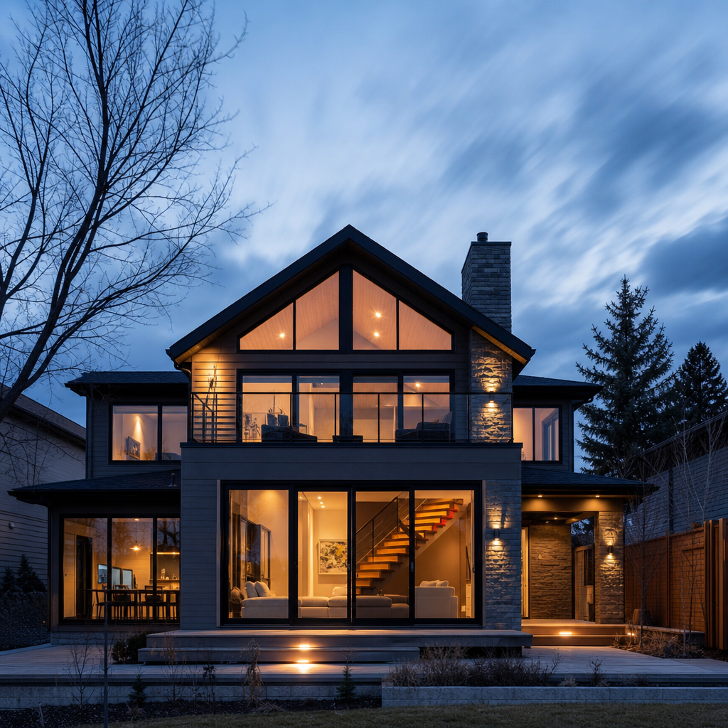
Roof assembly longevity and building envelope durability in Alberta depend on rigorous compliance with attic ventilation and clearance standards as enforced by the National Building Code - 2023 Alberta Edition (NBC(AE)). Code references, clear dimensioning, and explicit drafting detail on residential plan sheets are required to secure permit approval and to minimize deficiencies at construction and inspection phases.
Detailing Attic Ventilation Systems & Net Free Area Calculations on Residential Drawings (ABC 9.19.1.)
Section 9.19.1 of NBC(AE) mandates quantifiable, distributed attic ventilation for all insulated roof-ceiling assemblies in Alberta. Plan sheets must reflect these requirements with calculations, locations, material specs, and clarifying notes.
Quantitative Vent Area Ratios and Drawing-Sheet Call-Outs
Article 9.19.1.2. stipulates that a minimum unobstructed vent area of 1/300 the insulated ceiling area must be provided for standard sloped roofs. For slopes less than 1 in 6 or joist-constructed roofs, the required net free area (NFA) doubles to 1/150 of the insulated ceiling area. Intake (soffit/eave) and exhaust (ridge/gable/roof) vents must be distributed uniformly and located on opposing sides to induce effective airflow across the attic.
Drawings must display:
- Ventilation Notes: E.g., “Attic ventilation provided per NBC(AE) 9.19.1. Net free area calculations and vent type/location schedule provided.”
- NFA Calculation Tables: Tabular breakdown of required and provided NFA (sq. in. and sq. ft.), input attic area, chosen roof slope, selected vent types, and code reference. Example:
Attic Area: 1500 sq ft Required NFA (1/300): 5.0 sq ft or 720 sq in Intake (Soffit): 360 sq in Exhaust (Ridge): 360 sq in Complies with 9.19.1.2. - Roof Plan Vent Locations: Graphic symbols and labels distinguishing vent type: “SV” (soffit vent-model #, NFA per vent), “RV” (roof vent), “GV” (gable vent), "RV" (ridge vent).
Sections and details are required to show both airflow paths and the spatial relationship of baffle boarding, vent inlets/outlets, and insulation boundaries (callout “Minimum 25 mm airflow space between insulation and roof sheathing per 9.19.1.3.”).
Practical NFA Calculation and Plan-Review Redlines
Exact NFA is essential for code compliance and performance-manufacturer data for effective vent open area (accounting for screens and louvers) must be used. Common plan-review comments include:
- “NFA based on gross vent dimension, not net free-provide manufacturer data for actual open area.”
- “Required NFA not achieved at eave vents; respecify vent frequency/size or provide supplemental detail.”
- “Vent area imbalance-intake and exhaust must be approximately equal. Revise layout for even distribution.”
It is a standard expectation in Alberta jurisdictions for the calculation method and the compliance section (e.g., NBC(AE) 9.19.1.2.) to be explicitly cited in both notes and schedules. Omission is a common cause of plan redlines.
Dimensioning, Materials, and Code Call-Outs
All vent openings must have corrosion-resistant mesh (1/16"-1/4" per NBC(AE)) to prevent animal ingress. Vents should be dimensioned based on NFA output, not grille size, and detailed as part of a schedule (in alignment with manufacturer's listings). Roof and eave vent sizing, run-length, and spacing must be dimensioned in both plan and section. All vent products must conform to CAN3-A93-M for airflow characteristics.
Airflow must not be obstructed by insulation or structure; insulation baffles, scabbed spacers, or site-fabricated channels must be shown at every low vent location, sized minimum 25 mm deep over the full width of the vent opening. Where necessary due to framing or geometry, enlarged detail views must clarify how clear airflow is maintained.
Drafting Required Clearances for Attic Penetrations, Equipment, and Fire Separation (ABC 9.21., CEC)
Plan sets for Alberta residential projects must address all attic penetrations-chimneys, ducts, exhausts, mechanical lines-with clear, dimensioned separation from combustibles and detailed sealing or firestopping. NBC(AE) Section 9.21 and specific CEC provisions guide these requirements.
Chimney, Duct, and Joist Clearances: Explicit Dimensioning
Section 9.21.5.1. and 9.21.5.2. demand:
- Minimum 50 mm clearance from the exterior surfaces of masonry or concrete chimneys to wood framing.
- 12 mm minimum between chimney and combustible subflooring; 150 mm to cleanout openings.
- 290 mm of solid masonry between combustible supporting members and the inside flue if joists/beams rest atop a chimney wall (9.21.5.3).
All these offsets must be labeled “xx mm Clearance-Per NBC(AE) 9.21.5.X” directly on section details and plans at each relevant intersection. Any reduction of clearance by means of shields or insulation must reference the code basis explicitly or cite an approved variance/STANDATA, such as Variance 19-BCV-017 for protected vented soffits.
Penetration Sealing, Fire Separation, and Material Specs
Plan sets must show every attic penetration with a clouded section detail or enlarged call-out. Standard notation, e.g., “Seal annular gap with non-combustible mineral wool, full depth, typ.-per NBC(AE) 9.21.5.2.” must be included, with material spec (e.g., brand of firestop sealant) if required by local jurisdiction or builder specification. Schedules should list each material (gypsum, firestop, mineral wool) and their fire-resistance rating, as well as compliance mode (e.g., “ASTM E136, Type X gypsum, 12.7 mm min.”).
Where penetrations from exhaust ducts are proposed in attic assemblies, mechanical plans must include cross-reference to detailed assembly section showing clearances, insulation wrap (if required), fire caulking, and any planned fire damper omission with documented supporting variance-“Fire damper omitted per STANDATA 19-BCV-004, see mechanical notes.”
Plan-Review Redlines and Municipal Enforcement Trends
Common plan-review rejection notes include:
- “Chimney-to-framing clearance not dimensioned or code-cited.”
- “Annular space at duct penetrations lacks explicit firestopping note.”
- “Soffit vents shown in proximity to required fire separations contrary to [local bylaw/reference]. Revise as per Alberta STANDATA 19-BCV-017 or sheath soffits in min. 12.7 mm Type X gypsum board.”
Localized amendments regarding fire protection of soffits near property lines or between dwellings require either omission of eave venting or upgraded materials at these locations, always noted with referenced Alberta Building Code-Variance numbers or citations.
Specifying and Detailing Code-Compliant Attic Access Openings and Headroom on Plan Sets (ABC 9.5.10.)
Section 9.19.2.1. of NBC(AE) 2023 mandates attic access (hatch) provision where the attic or roof space exceeds 3 m² in area and has a height over 600 mm (24") across any length or width exceeding 1 m. Construction drawings must demonstrate compliance through precise dimensioning, location, and framing notes.
Access Hatch Size, Framing Detail, and Placement on Drawings
Default minimum hatch dimensions are 550 mm x 900 mm (approximately 22" x 36"), but for attics serving a single dwelling unit the minimum area is 0.32 m² with neither side less than 500 mm (~20"). Standard section and plan call-outs include:
- “Attic access: 550 x 900 mm, not less than 600 mm clear height over opening. NBC(AE) 9.19.2.1.”
- Or: “Attic access (single dwelling): 500 x 650 mm, 0.32 m², min. 600 mm clear headroom per 9.19.2.1(1)(b).”
- Dimension lines and hatch symbol on RCP (reflected ceiling plan) and main floor/second floor plan with cross-reference to section.
Location should be “readily accessible”; hatches must not open into obstructed, reached-by-ladder, or confined spaces. Plan reviewers commonly state:
- “Access hatch placed over fixed millwork-relocate to unobstructed hallway per 9.19.2.1.”
- “Headroom dimension not called out. Provide 600 mm minimum above hatch for access compliance.”
Insulation, Air Sealing, and Plan-Sheet Best Practices
NBC(AE) and EnerGuide/Step Code expectations in Alberta require that attic hatches maintain continuous air and thermal barrier: details must include:
- “Hatch cover, insulated to R-40 min., sealed with closed-cell weatherstripping all sides. Cam latch for air seal (see detail A6).”
- “Framing: Double 2x8 header each side, trimmer studs min. full joist depth, refer to structural sheet S3.”
Provide section details that depict:
- Location of batt or rigid insulation within cover.
- Weatherstripping layer, continuous.
- Latching hardware and any required finished surface for fire/smoke separation.
Insufficient air sealing or under-insulated covers are frequent deficiency items on blower-door testing and plan-review notes-explicit dimensioned and annotated details are required to preclude such issues.
Ensuring Continuous Air Barrier, Insulation, and Ventilation Channels at Eave Details (ABC 9.19.1.2., 9.25.)
Commissioning drawings for Alberta homes must explicitly show how attic ventilation (airflow paths) interface with the building envelope’s thermal and air barrier layers at eaves. NBC(AE) 9.19.1.2. and 9.25.3.1. govern these details, with strict requirements to prevent air leakage and maintain insulation continuity.
Air Barrier and Insulation Continuity: Section Detailing and Notation
Details must illustrate a continuous “air barrier system” (e.g., sealed poly vapour barrier or air-impermeable spray foam) transitioning over the top wall plate into the roof plane, uninterrupted by framing or ventilation hardware.
Standard section call-outs:
- “Continuous air barrier membrane sealed at wall-roof interface-NBC(AE) 9.25.3.1.”
- “Baffle (25 mm minimum depth) maintains unobstructed vent pathway above insulation-per 9.19.1.3.”
- “Insulation pack extends full width to outer edge of exterior wall top plate-no thermal bypass.”
Notation should specify insulation type/by R-value at each assembly layer (“Blown-in fiberglass R-40 typ.”) and membrane characteristics (“15 mil polyethylene air/vapour barrier with taped and gasketed joints, ASTM E2178, max 0.02 L/(s·m²) @75 Pa”).
Ventilation Pathways and Material Transitions at Eaves
Attic vent chutes or insulation baffles must be dimensioned minimum 25 mm deep by rafter/truss cavity width-constructed of moisture-resistant cardboard, extruded polystyrene, or rigid plastic as per code and manufacturer listings. Ridge- and soffit-vent components must be labeled with make/model and NFA per vent data. Section details “bubble” or leader lines should tie each component to a label/schedule.
Where vented eaves project <1.2m from a property line or adjacent buildings, local amendment or variance (see STANDATA 19-BCV-017) may require:
- Omission of vented soffit in affected area; or
- Upgrading soffit material to “12.7 mm Type X gypsum board” or “0.38 mm sheet steel-see plan note and section C9.”
Plan-review comments routinely include:
- “Vent chutes not shown-provide detail showing maintenance of 25 mm ventilation channel.”
- “Air barrier continuity at wall/roof plate not clearly detailed. Revise to show membrane transition.”
Unvented roof assemblies (STANDATA 19-BCV-022) require full insulation, continuous vapor-impermeable membrane, and code-cited “no-vent” notation with listing of compliant details-drawings must alert both plan-review officials and site trades to the alternate assembly with explicit boxed note on every relevant sheet.
Addressing Complex Attic Geometries and Obstructions for Ventilation & Clearance Compliance
Irregular attic spaces, intersecting rooflines, hip/dormer valleys, and dropped ceiling/bulkhead intrusions present a challenge for code-compliant ventilation. The NBC(AE) and Alberta enforcement authorities expect site-specific drawing solutions for these conditions-omitted or generic notes are likely to be rejected during plan review.
Distributed Vent Calculations and Custom Detailing
Where hips, valleys, or attic partitions subdivide the roof space, plan sets must include separate NFA calculations for each distinct volume, not simply the gross attic area. Each isolated section must have its own intake/exhaust calculation and venting schedule-non-contiguous airflow paths cannot be assumed. Plan notes should state:
- “Skillion/dormer/partitioned attics-NFA calculated and provided per isolated volume. Refer to schedule V-1, V-2, V-3.”
Choke points-such as structural valleys, crossing beams, or mechanical runs-require drawn airflow paths and/or detail “callouts” (“Air redirect baffle at valley-section 7B”), along with dimensional notation of clear passage (“Maintain 25 mm air passage minimum at all constrictions-reference detail D4”).
Obstructions, Insulation Blockages, and Code Enforcement Trends
Where insulation or framing interrupts intake-to-exhaust airflow, a frequent plan-review redline is:
- “Obstructed airflow at [location]; provide baffle/location detail or increase vent density.”
Solutions include staggered venting, locally upsized or booted vents, rigid air chutes, or engineered air transfer devices. All such devices/materials must be listed with product standard and open area, dimensioned and scheduled on plan. Schedule should cross-reference both section/detail numbers and the relevant code requirement (“Intake air transfer boot, Model X, NFA 56 in², see detail C9, per NBC(AE) 9.19.1.2.”).
Complex Penetrations and Soffit Constraints
Chimneys, mechanical vents, electrical mast penetrations, and drop ceilings reduce available vent area and accessible airflow paths. If vented soffits are limited by fire separation requirements (e.g., within 1.2 m of a shared property line or adjacent structure), drawings must note alternate exhaust means or reference Alberta STANDATA 19-BCV-017 with clear legend annotation:
- “Soffit vent omitted in fire separation zone-see ABC 9.10.15.8.(2) & STANDATA 19-BCV-017. Upgrade soffit to 0.38 mm steel, extend ridge vent per Section 5A-5B.”
Plans must clarify “Provide minimum 150 mm offset to combustibles at chimney penetration per 9.21.5.1. Dimension on section view 9.”
Multiple attic spaces at differing levels-split-level, multi-gable, or integrated flat/hip designs-require isolated vent and penetration calculations for each distinct volume. Exhaust/intake balance must be diagrammed for each, scheduled, and cross-referenced to the plan. Omission leads to frequent deficiency notes during municipal review and increases risk of on-site scope conflict or costly corrections.
Integrated Compliance: Drafting for Construction, Plan Review, and Endurance
Construction drawings for Alberta residential permits must synthesize NFA, penetration clearance, air/thermal barrier continuity, and bespoke solutions for complex geometries-all anchored in explicit section, dimension, and detail call-outs. Only through unambiguous, code-referenced documentation on plan sheets, including:
- Dimensions: All clearances, vent sizes, offsets, insulation depths explicitly labeled to code minimums.
- Section Details: Each unique roof/eave/penetration condition, with labeled airflow paths and material specs.
- Schedules: Vent and access hatch schedules listing all locations, sizes, NFA, material specs with code references.
- Code Reference Notes: Citation of every relevant NBC(AE), CEC, or STANDATA section on each detail or schedule.
- Redline-Proofing: Proactive addressing of known plan-reviewer comments in both graphical and note format.
Properly detailed and dimensioned sheets streamline reviews, prevent misinterpretation by trades, align with current Alberta code and enforcement trends, and protect the long-term performance of the building envelope.
Kingsway Drafting & Design brings deep code expertise and construction detailing rigor to every Alberta residential project-delivering drawings that anticipate both permit reviewer and job-site needs.