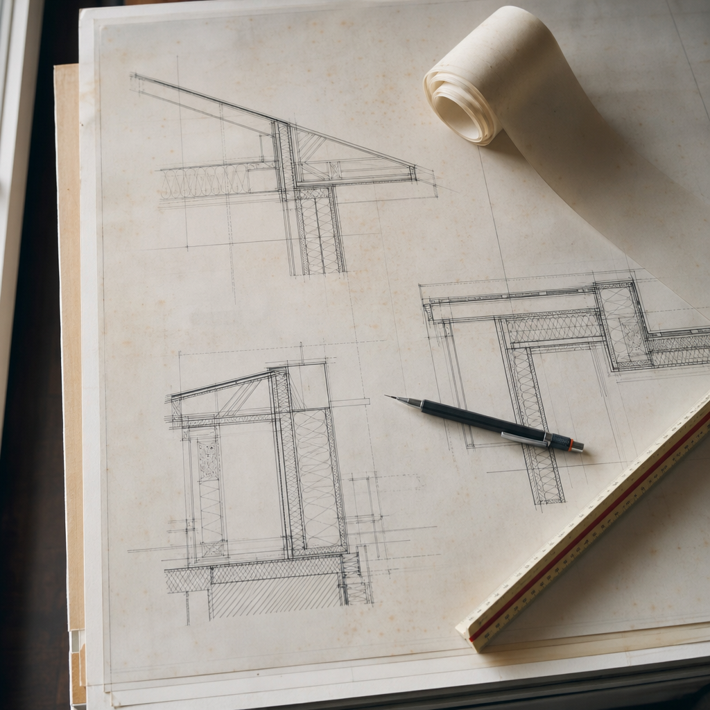
The continuity of air barrier systems at roof-to-wall and parapet junctions in Alberta’s homes remains a technical linchpin for envelope performance, energy efficiency, and compliance with the National Building Code - 2023 Alberta Edition (NBC(AE)). As building codes and energy standards advance, drawing sheets and detail call-outs face new scrutiny during permit review and construction, especially when these junctions are not clearly delineated or dimensioned. On Alberta plan sheets, air barrier pathways at these intersections carry implications for insulation continuity, code call-outs, specification of membrane upstands, and sealing requirements. Seemingly minute omissions on construction documents can escalate to significant plan-review redlines and job-site disputes.
Code Requirements for Air Barrier Continuity at Roof-to-Wall and Parapet Junctions
NBC(AE) Article 5.4.1.1 and Section 9.36.2.9: Explicit Requirements on Drawings
Continuous air barriers are mandated for every assembly that separates conditioned interior spaces from the exterior, as detailed in NBC(AE) Article 5.4.1.1. This requirement becomes particularly acute at locations where differing assemblies meet-such as roof-to-wall and parapet transitions-in part because discontinuity commonly arises from trade intersections and insufficient site-verified detailing.
Section 9.36.2.9 specifically prohibits air leakage into or out of conditioned spaces and requires construction of a continuous air barrier system at envelope interfaces. These code requirements must surface explicitly in the drawings-through detailing, dimensioning, and annotated technical instructions-to withstand permit scrutiny.
Provincial Amendments and Climatic Response
Alberta’s adoption of the National Building Code includes certain amendments targeting local climate extremes. Provincial bulletins reinforce that designers must exceed mere textbook standards, incorporating both extensive air barrier upstands and industry-preferred junction materials. Detailing on plans thus demands Alberta-specific conventions, requiring referential call-outs to regional product standards or typical assembly methods where applicable.
Dimensioning Requirements and Minimums for Membrane Upstands
At parapet-to-roof and wall-to-roof junctions, code-minimum upstand dimensions must be respected and explicitly shown. Typical dimensioning-such as “Roofing membrane to extend 200 mm (8 in) minimum vertically up face of parapet, above finished roof surface”-should appear both as a symbology cue and a written note, per province-endorsed guidelines.
The Role of Detailed Drawings and Annotations in Code Compliance
Referencing NBC(AE) on Plan Sheets
Redlines from permit review frequently cite incomplete or unclear air barrier transition documentation. NBC(AE) Article 5.4.1.1 is regularly referenced by municipal plan reviewers: “Air barrier system continuity at all transitions (roof/wall/parapet) per NBC(AE) 5.4.1.1-Provide explicit, continuous detail referencing material and sealing method.”
Details lacking reference to allowable air barrier paths invite review comments demanding, for example: “Cloud area-Provide typical roof-to-wall air barrier transition, showing membrane lapping wall and roof assemblies, min 200 mm upstand, and referenced air barrier product.”
Conventions and Best Practices for Sheet Call-Outs
- Detail Call-outs: On overall plans and roof plans, all intersection points (e.g., where a parapet meets a sloped roof, or where a low-slope roof returns to an exterior wall) must link directly to keyed detail bubbles (e.g., “See Detail A-7: Roof/Parapet Air Barrier Transition”).
- Continuity Arrows and Paths: Use heavy dashed lines or color-coded arrows following the line of the air barrier through assembly intersections, ensuring path is uninterrupted from wall membrane, upstand, across roof, and around parapets.
- Material and Product Notes: Call out specific products and standards adjacent to detail sections (e.g., “Peel-and-stick membrane meeting ASTM E2178 air permeance ≤ 0.02 L/(s·m²) @ 75 Pa”).
- Sealing Methods: Diagram all laps, joints, and transitions with hatch or shading and add notes such as “Continuous polyurethane sealant, compatible with membrane and substrate, applied to all terminations”.
Dimensioning Air Barrier Upstands and Transitions
Dimension lines must explicitly define the vertical extension of membranes at all junctions: “Self-adhered membrane, min 200 mm (8”) above finished roof elevation at wall intersection and full wrap at parapet terminations.” When drafting eave details where roof meets exterior wall, include notations such as “Air barrier to transition from wall sheathing membrane up and under roofing membrane-lap min 100 mm (4”) and seal-all per 9.36.2.9 NBC(AE)”.
Job-site assemblies are only as precise as the details depicted on drawings; measureable upstands, lap widths, and closure dimensions are not optional elements but clear inspection references.
Common Plan-Review Redlines and On-Site Issues
Frequent Redline Comments
- Discontinuous Air Barriers: “Provide continuous air barrier path at roof/wall juncture-current detail terminates membrane at plate, does not show transition onto roof.”
- Ambiguous Sealing Method: “Detail lacks notation for taping/sealing at transition-clarify how membrane is extended and terminated/sealed at frame interface.”
- Product/Material Omission: “Air barrier material unspecified-list compatible product and indicate compliance with ASTM E2178.”
Drawings as the Arbiter of Field Quality
Field installation often reveals exactly what’s missing from the detail sheet: when membrane upstands are dimensioned ambiguously-“extend as required”-crews will stop short of upstand minimums; when sealing methods are not depicted, corners leak; when incompatible or generic products are listed, the air barrier’s performance can be fatally weakened.
By translating code and municipal precedent into precise graphical conventions, drawing sheets reduce interpretive error. Typical notation on plan-section bubbles might read: “Detail C-3: Roof-to-parapet air barrier-refer to product spec 07 27 00. Apply self-adhered vapour permeable membrane, min 200 mm vertical up parapet, continuous tape seal at joint.”
Specifying Air Barrier Materials, Dimension, and Ratings for Alberta Construction
Material Selection by Standard
All air barrier materials selected for Alberta residential envelopes require documented air permeance not greater than 0.02 L/(s·m²) @ 75 Pa, as tested to ASTM E2178 (see ASTM E2178). This standard must be embedded in the project specifications and cited directly on detail sheets, not left for the tender or shop drawing phase.
On plan sections, call out typical wall-to-roof transitions as: “Wall air barrier membrane-peel-and-stick, air permeance ≤ 0.02 L/(s·m²) as tested, wrap continuously up and over interface” as both a notation and a compliance verification for field inspectors.
Minimum Upstand Dimensions and Detailing
Provincial reference documents such as the Alberta Infrastructure Technical Design Requirements and best-practice manuals specify that roof membrane must extend at least 200 mm (8 in) above finished roof level onto parapet or wall. On all relevant interior and exterior elevations, section bubbles should show this dimension as both a graphical marker and a note, ensuring visible code conformity pre-permit.
Where upstand cannot be achieved due to assembly constraints (e.g., sloped shingle roofs), detail notes should clarify transitions: “Extend self-adhered membrane up exterior wall min 100 mm (4”), under lap to over-sailing eave membrane, continuous seal at rake/soffit terminations.”
Sealing and Closure Practices
Misalignment between trades at junctions is frequently to blame for post-construction air leakage or failed blower door tests. Drawings should therefore key explicit sealant notes at every junction: “Seal all membrane laps and substrate transitions w/ low-modulus polyurethane sealant; ensure continuous bond to substrate; compatible with both roof membrane and wall assembly as per spec section 07 92 00.”
Any insulation in these details must be called out for continuity-with dimensions to show uninterrupted coverage and tied graphically to air barrier location: “Exterior mineral wool insulation to extend flush to roof/wall intersection, no gaps, no compression, shown in section A-A.”
Material Compatibility and Performance at Junctions
Product Selection Relative to Substrates
Material incompatibility at transition zones is a frequent source of both building envelope failure and plan-review delay. On Alberta projects, both the RCABC Roofing Practices Manual and provincial technical bulletins advise use of membranes and sealants proven compatible between different adjacent assemblies-wood, masonry, SBS roofing or flexible parapet wraps.
Plan details must therefore include both named products (e.g., “Blueskin VP160 or approved equal”) and reference to test data (ASTM E2178 for membrane, ASTM C920 for sealant), or else risk deferred approvals and on-site substitution that may not meet performance targets.
Annotated Compatibility Notes and Drawing Sheet Practice
Adjacent to every detail illustrating roof-to-wall or parapet transitions, notation should clarify: “All air barrier membranes and sealants at roof/wall/parapet junction to be compatible with adjacent assembly product; contractor to verify manufacturer approvals prior to installation.” In practice, this note often appears as a footnote on detail sheets or as a general note above detail keys pertaining to critical transitions.
Reviewer comments often require this step: “Revise detail to include air barrier/roof membrane compatibility; submit data sheets as requested.” Such annotations streamline both permit issuance and submittal review.
Standardized Drawing Conventions for Air Barrier Detailing at Junctions
Detail Reference Indexing and Drawing Numbering
All sheets addressing envelope penetrations or assembly changes should group details in a standardized manner (e.g., Sheet A-501: Typical Air Barrier Transitions), referenced from both plan view call-outs (bubble with “501/A”) and sectional cuts. On metric plans, use dual-dimensioning where relevant (e.g., 200 mm (8") upstand), ensuring dimension clarity for both local and out-of-region stakeholders.
To aid field trades and inspectors, include a keyed “Air Barrier Continuity Path” diagram on at least one drawing sheet, showing the entire exterior enclosure with highlighted continuous air barrier, labeled membrane products, transition details keyed to sheet and detail numbers, and code reference (e.g., “Continuity per NBC(AE) 5.4.1.1 & 9.36.2.9”).
Material Notes, Legends, and Sealant Application
- Material Legends: Indicate on the detail sheet all membrane layers, insulation materials, substrate types, sealants, and transition strips via sectional hatching or legend keys (e.g., “1 - Self-adhered membrane (Blueskin VP160), 2 - Polyurethane sealant, 3 - Extruded polystyrene insulation, etc.”).
- Sealing Directional Cues: Use directional arrows with text indicating “Lap and seal membrane continuously from wall air barrier, upstand at parapet, under roof membrane; min 100 mm lap with staggered joint seal.”
- Fire and Air Performance Ratings: Where required, indicate on the detail “Air barrier assembly tested to ASTM E2357-submit test report prior to installation.”
Translating Code and Drawing Conventions to Field Practice
Communication from Sheet to Site
Field teams rely on the clarity of construction documents. Discrete air barrier paths-clearly dimensioned, with arrowed transitions, labeled upstands, and closure instructions-reduce interpretation risk, expedite inspection, and defend against incomplete installs. Template call-outs such as “Continuous air barrier path-see Section B-B, Sheet A-501” should be repeated at every roof termination, parapet wall, and intersection.
On the job site, vague notations are one of the principal causes of missed or skipped continuity steps. Notational clarity-“MEMBRANE TO EXTEND MIN 200 mm UP PARAPET WALL, LAP UNDER ROOF MEMBRANE, SEAL ALL EDGES”-must be legible in all weather and schedule conditions.
For complex details-such as intersecting insulated parapets-a full-scale (1:5 or 1:2) blow-up is indispensable, with exploded hatching and product tags ensuring no ambiguity at intersections or edges.
Plan Review and Permit Approval Stakeholder Expections
Municipal and provincial plan reviewers will flag vague, generic, or missing details at air barrier junctions. Most Alberta cities expect to see both macro building section indications (e.g., Section A-A through entire roof/wall envelope) and micro-detail insets with call-out bubbles, upstand dimensions, and explicit sealing routines. Where trade discipline interfaces converge (roofing/framing), drawing sheets must bridge the gap-showing “handoff” of air barrier continuity so all trades acknowledge their responsibility.
Redlined comments for resubmission might include: “Revise Section 5/A-501: Air barrier at parapet discontinuous at coping-show upstand, membrane lap, compatible seal.” To avoid cycles of review, embed every step of the transition, including “tie-ins” and backup membrane locations, into the drawing sheet and spec package.
Examples from Reference Standards and Practice Manuals
RCABC Roofing Practices Manual: SBS Parapet-Wall Connections
Alberta and Western Canadian best-practice documents such as the RCABC Roofing Practices Manual provide both section and plan details showing the correct layering of SBS membrane, upstand, and continuous lapping onto both parapet and adjacent wall. These sample details are routinely cited by Alberta inspectors and specifiers as the “standard of care” for roof/parapet transitions-especially for low-slope (SBS, PVC) roof assemblies.
Typically, drawing sheets will include call-outs such as: “SBS base sheet to extend min 200 mm up inside face of parapet, fully adhered, primed substrate, lapped under cap flashing; air barrier membrane to lap min 100 mm under base sheet, full closure seal.”
City of Edmonton Air Barrier Position
Municipalities such as Edmonton publish definitive position papers on air barrier detail requirements at envelope junctions. Their published detail sheets show both wall-to-roof continuous membrane wraps and explicit closure of membrane and insulation at parapet corners (see: edmonton.ca position paper). This guidance often leads to the following plan-review convention: “Detail must show air barrier lap and compatible sealant encasement at all joints; indicate direction of continuity with arrows or hatch.”
Coordinating Air Barrier Detailing in Multi-Trade, Multi-Phase Construction
Trade Accountability and Sequencing in Drawings
Drawings should anticipate sequencing challenges at junctions. When a wall air barrier is installed before roofing, notations must anticipate necessary tie-ins: “Temporary closure at roof deck by framer; roofing trade to remove closure, extend roof membrane up wall, lap and seal to wall air barrier membrane; visually confirm full overlap and seal before concealment.”
Coordinate drawing sheet notes with project specifications and structural details, especially in parapet zones or at sloped soffit returns, to ensure insulation and air barrier are concurrent and uninterrupted. Include in sequencing notes: “Do not install coping cap until HVAC, vent penetrations, and sealant inspection are complete-field verify continuous air barrier at each step.”
Quality Control, Inspection, and Drawings as Inspection Aids
Drawings are frequently used by testers during air leakage (blower door) tests to verify compliance with NBC(AE) airtightness provisions. Well-annotated, dimensioned details allow rapid inspection and enable clear direction for remediation, should test results fall below code minimums.
As a best practice, insert a reference drawing such as: “Schematic: Air Barrier Test Path-highlighted in red-continuous from foundation through floor, wall, and roof assemblies; all penetrations, transitions, and laps sealed per Sheet A-501 details.”
Summary: Ensuring Code-Compliant Air Barrier Continuity at Junctions
Achieving code-compliant air barrier continuity at Alberta roof-to-wall and parapet junctions is fundamentally a matter of rigorous, explicit drafting on plan sheets. NBC(AE) 5.4.1.1 and 9.36.2.9 require continuous, clearly detailed barriers; municipal reviewers will demand section details with product notes, lap dimensions, sealing instructions, and path indications for every envelope transition. Drawings must display all product selections, upstand minimums (200 mm at parapets; 100 mm at eaves), and hatching for insulation and vapour control. Annotation of sealant types, lap directions, and trade responsibilities must appear in detail insets and referenced specification sections. Where these conventions and details are missing, expect costly plan-review delays, site correction, and energy underperformance.
For Alberta construction, drawing sheets are the foundation for both code interpretation and ultimate building performance at these critical enclosure junctions.
Kingsway Drafting & Design provides detail-precise code-compliant documentation for Alberta residential envelopes, including expert coordination at all assembly transitions.