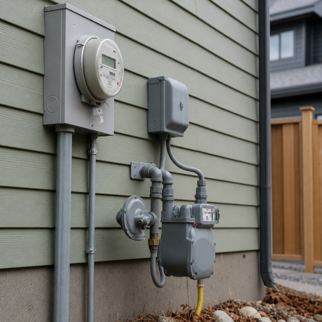
Exterior utility meter placements and service connection details on Alberta residential site plans are dictated by a complex intersection of code requirements, utility-provider technical bulletins, and plan review convention. Field execution flows directly from the clarity and precision of their representation on plan sheets-especially true for meter bases, regulator vents, and service entry locations, where non-compliant placements cascade into costly delays, change-orders, and inspection failures. Compliance hinges not on general interpretation, but on crisp dimensioning, observance of annotation norms, and anticipation of plan review methodology. The following sections break down in exhaustive technical detail how minimum clearances and coordination measures for electrical, gas, water, sewer, and multi-utility layouts must show up in Alberta drawings, including real code call-outs, dimensioning strategies, representative plan-review redlines, and sheet-level notation conventions for field constructability.
Electrical Service Entrance Clearances: CEC, Alberta Building Code, and Utility-Provider Sheet Requirements
Regulated Meter Placement and Service Equipment Location
The Canadian Electrical Code, Part I (CEC) and the Alberta Building Code (ABC) converge with utility-specific installation bulletins to precisely govern electrical service entrances on Alberta residential projects. CEC Rule 6-206(1)(c) mandates: the service disconnecting means must be “located as close as practicable to the point where the service conductors enter the building.” Direct distributor standards in Alberta generally require the conductor length inside a dwelling to be no more than 3.0 m; when unavoidable, a maximum of 7.5 m may be allowed, but only if protected in rigid metal conduit (Alberta STANDATA Bulletin 21-ECB-006).
On plan sheets, main disconnects must be visibly dimensioned on floor plans and elevation views relative to the point of electrical entry, with call-outs such as: “Main disconnect: located 0.9 m from entry; cable in 2” RMC, total run 3.0 m (max per CEC 6-206)”. Plan reviewers will often redline: “Service disconnect exceeds maximum allowable distance from point of entry; revise to comply with CEC Rule 6-206(1)(c)” if that location or run-length is not immediately clear.
Meter Base Heights and Access Clearances
ENMAX and FortisAlberta, the principal distribution utilities, specify that the centerline of any meter base must sit 1.5 m to 1.8 m above finished grade. Practically, drafted elevations must dimension from final grade datum to the mid-point of meter symbol, annotated as: “ELEC METER CL: 1.5 m min, 1.8 m max AFF (per ENMAX/UTILITY STD)”. For field access, a minimum clear, unobstructed working area of 1.0 m wide by 2.2 m high in front of the meter-unencumbered by enclosures, foliage, bollards, or adjacent construction-is mandatory for utility approval. Plan sets require a dashed rectangle (often hatched) to be overlaid on site plans in front of the meter box, labelled: “Required clear access zone, 1.0 m x 2.2 m, do not encroach”.
Common plan-review comments: “Insufficient clearance in front of meter base; ensure 1m x 2.2m unobstructed area as per utility requirements”. Drafters must annotate these clear zones and reinforce the restriction with notes in both the site plan legend and electrical details.
Service Mast, Overhead Conductor, and Wall Attachment Details
Service masts for overhead supply (4 or 5 wire) are detailed schematically at wall sections and at the electrical riser diagram, per CEC Rule 6-112 and local utility protocols. The code-prescribed attachment point from finished grade to service conductor entry must not exceed 5.5 m-otherwise a separate pole or riser structure is required. Dimension lines from grade to the service-head call out: “Service mast upper attachment: 5.0 m AFF (max 5.5 m per CEC 6-112, ENMAX SEC. 4.2.1)”.
- Overhead conductor clearances: Minimum 5.0 m clearance above pedestrian-accessible grade, 4.0 m above residential driveways, and 5.0 m above commercial driveways. Dimensioned on elevation sheets or utility coordination plans with labeled leader lines: “O/H Conductor: min 5.0 m clearance above walking grade (CEC Table 34, ENMAX STD)”.
- Mast materials: Minimum 2” rigid metal conduit (RMC) for 200A services. Noted in call-outs-“2” RMC, sch. 40, for service mast, (steel, per FortisAlberta 3.2.3)”.
- Wall bracing: Section details must show U-bolts and mast clamp plates at specified vertical intervals, with brackets/fasteners capable of resisting service drop strain loads. Noted as: “Service mast fastened at 1.2 m and 3.0 m intervals w/ (2) 1/2” galvanized bolts to wall studs”.
Redlines frequently force clarification where structure is ambiguous: “Service mast lacks adequate bracing; provide structural details demonstrating compliance with ABC load requirements”.
Conductor, Disconnect, and Meter Equipment Specifications
- Conductor size: 200A services require minimum 2/0 AWG copper or 4/0 AWG aluminum (CEC Table 2).
- Disconnect ampacity rating: Main breaker sized per calculated load, but no smaller than 100A for new dwellings. Equipment schedules must specify: “Main disconnect: 200A, 2P, NEMA 3R, lockable outside”.
- Grounding/bonding: Ground electrodes called out as: “6 AWG copper ground, CEC Rule 10-700, (2) 2.4 m rods, 1.5 m apart, driven flush”.
Recommended plan-sheet structure:
- Site Plan: Meter base and service mast/overhead feed with call-outs and clearances
- Elevation: Dimensioned vertical locations for meter and conductor attachments
- Electrical Riser: Schematic showing conductor runs, disconnect location relative to entry
- Legend: Utility-mandated access zones and mounting requirements
- Keynotes: Code references (e.g., “All electrical clearances per CEC 6-112, 6-206.1(c), ENMAX Svc Manual 3.2.1”)
Natural Gas Meter and Regulator Vent Clearances: CSA B149.1-2025 & ATCO Alberta Standards
Vent and Meter Placement to Openings, Intakes, and Ignition Sources
The CSA B149.1-2025 Natural Gas and Propane Installation Code, enforced province-wide as of March 1, 2026, and ATCO Gas’s latest field bulletins, prescribe clearances that are rigidly enforced during both plan review and field inspection.
Key requirements, as directly quoted from ATCO and CSA B149.1:
- Building openings: The service regulator relief vent must be at least 3.0 m (10’-0”) from any windows, doors, or operable building openings. Notes on plan: “3.0 m min. (10’-0”) from regulator vent to any egress window, operable door (CSA B149.1-2025 6.5.3, ATCO App. A)”.
- Air intakes:
- For mechanical/fresh air intakes > 219 mm (8”) diameter: maintain 3.0 m (10’-0”) minimum.
- For intakes ≤ 219 mm (8”): minimum 1.0 m (3'-3”).
- Sources of ignition: Minimum 1.0 m (3'-3”) from regulator relief vent to any electrical device, open flames, exterior outlets, or other ignition sources. Call-out: “Maintain 1.0 m (3'-3”) min. to all ignition sources (CSA B149.1-2025 6.21.2)”.
ATCO frequently flags plans where these dimensions are not explicitly drawn: “Gas meter set shown within 3.0 m of window; revise to comply with CSA B149.1 and ATCO Gas install guide Section 3.1”.
Meter Sets, Vent Piping, and Material Specifications
- Gas meter mounting: Must be exterior and accessible for reading, 300 mm minimum above final grade. Sheet note: “Gas meter: 0.3 m min. above grade, accessible location”.
- Regulator vent piping: Vent pipe must match regulator outlet size (min. ID 6 mm), terminate with insect/rain guard, and remain rigidly fixed. Typical detail call-out: “Regulator vent: 12 mm steel (sch 40), terminate with CSA-listed weather cap; total run 470 mm (see Detail 5/E4.2)”.
- Access and enclosure: Meters cannot be located in garages, crawlspaces, or beneath interior stairs; clear plan labelling is required for all “NO ENTRY” zones.
- Barrier protection: Meters adjacent to vehicle paths require bollards or guardrails. Call-out: “Provide (2) steel pipe bollards, painted yellow, 1.0 m apart, 900 mm above grade, 1.2 m embedment, per City DP Std. 7.4.1”.
Plan-Review Comments and Drawing Conventions for Gas Meters
- Redlines will state: “Insufficient gas meter relief vent clearance to air intake; reposition per B149.1-2025 Table 6.3.1”.
- Site and exterior elevation sheets must use:
- Triangle or square symbols for “GAS METER” and “REG VENT,” each tied to a legend with abbreviation and code reference.
- Dimension arrows from vent/meter to each proximate window/intake/ignition symbol, with direct code call-outs (e.g., “3.0 m min. B149.1-2025”).
- Hatched zones where meter placement is prohibited due to openings; labeled “No gas meter zone, see Detail 3/E2.4, B149.1-2025 6.5.3.”
Notes must instruct field to maintain the plotted dimensions; variance triggers test-fail at rough-in. Typical general note: “GAS METER, REGULATOR, AND VENT TO BE INSTALLED PER CSA B149.1-2025, ATCO GAS GUIDELINES, AND ALL LOCAL AMENDMENTS. DO NOT REDUCE CLEARANCES.”
Water Service and Sanitary Sewer Connection Detailing: ABC Part 7 and Municipal Standards
Depths, Backflow Protection, and Cleanout Placement
Alberta residential water and sanitary service connections are regulated by ABC Part 7 (Plumbing Services) and the NPC 2020, with further specification from local bylaws. Section 7.4.7.1 requires cleanouts for “every sanitary and storm drainage system…sufficient to allow the cleaning of the entire system.” Plan sets must show labeled circles (“C.O.”) at each required location: base of vertical stacks, change of direction over 45 degrees, and outside the foundation wall.
Dimension lines specify:
- Cleanout spacing: Pipes less than 3” require cleanouts at max. 7.5 m intervals for one-way rodding, 15 m for two-way. Noted: “Cleanout, 7.5 m max. one-way from stack, per NPC 7.4.7.2”.
- Cleanout sizing: Same as served line, up to 4” (100 mm); for 100-150 mm lines, 4” cleanout permitted.
- Backwater valves: Required on main building drain where risk of sewer backup exists (Section 7.4.6.4). Shown schematically: “Backwater valve (location: 2.0 m in from foundation), see Detail 2/P1.4, NPC 7.4.6.4”.
- Exterior cleanouts: Marked at property line “PL C.O.” with offset dimension to nearest foundation face and description: “Locate PL C.O. 0.6 m outside foundation wall, see City of Calgary Standard Dwg. S-1451”.
Water Service Specifications and Frost Protection
Alberta utilities and NPC 2020 require water service lines to be installed at sufficient depth to avoid seasonal freezing. Local bylaws (e.g., City of Calgary Waterworks Bylaw) enforce a minimum depth below grade, commonly 2.4 m except where frost depth data dictates more. This depth is dimensioned in section and plan as: “WATER SERVICE: 2.4 m min. below finished grade (see Site Section A-A)” and reinforced in pipe schedule (e.g., “Type K copper, 25 mm, 1034 kPa pressure rating, min. cover 2.4 m”).
Material call-outs:
- Water: “25 mm Type K copper/25 mm HDPE (CSA B137.1), 2.4 m min. cover, tracer wire for plastic, blue marking tape”
- Sewer: “100 mm PVC DR35 (CSA B182.1), solid core, cleanouts per NPC 7.4.7.2, 2% min. slope”
Cleanout and service alignments must never overlap or obstruct each other; conflicts result in municipal rejection: “Revise to separate water and sewer service entry by 1.0 m min. horizontally, per City Standard”.
Drawing Practices and Field Documentation
- Symbol legend includes “C.O.” for cleanout, “BWV” for backwater valve, “P/L” for property line connection.
- Site Plan overlays show routed “water” and “sanitary” lines with slope direction, entry depths noted at foundation.
- Enlarged details reference sheet and code (e.g., “Detail 4/P2.1: Typical foundation wall penetration, see NPC 2.4.5.1”).
Typical plan review comments:
- “Cleanout at base of stack not shown; add per NPC 7.4.7.1.”
- “Water line cover insufficient; revise cross-section to provide 2.4 m cover, or submit frost-depth justification.”
Integrated Utility Coordination and Conflict Resolution: Clearance Management, Utility Zoning, and Alberta One-Call Compliance
Horizontal and Vertical Separation of Utility Pathways
The National Building Code - 2023 Alberta Edition (NBC(AE)) Section 9.1.1.1 and 9.12.3, together with municipal utility corridor protocols, prescribe the spatial relationships between different service types. The most common enforced minimum is a horizontal separation of 1.0 m between all parallel utilities (e.g., gas, water, sewer, and electrical), to prevent cross-contamination, allow for emergency repair access, and respect physical plant requirements.
Plan and section drawings articulate this separation clearly:
- Utility runs are drafted in plan view using distinct line-types (e.g., long dash for gas, dot-dash for water, solid for sewer).
- Dimension arrows between parallel services labelled: “1.0 m min. horizontal separation (City Engineering Std. U-1047)”.
- Vertical crossings are shown in short cross-sections, with call-outs noting: “Gas line to cross 300 mm above/below water at intersection, provide 1.0 m offset each side, City of Calgary Std S-1716.
Conflicts-where, for example, an electrical lateral is within 0.5 m of a water main-are common redline triggers: “Revise utility layout to provide 1.0 m horizontal separation (NBC(AE) 9.12.3)”.
Utility Zoning and Site Plan Coordination Strategies
Modern Alberta subdivisions enforce precise “utility rights-of-way” (URW), typically 3.0 m to 6.0 m wide at lot frontages, each with prescribed utility corridors: gas (north side), electric (south), communications (central), water/sanitary (at property line). Site plans must label and dimension each utility band, with shading or hatch indicating the zone and direct pipe runs kept within these boundaries unless variance is explicitly approved. An exemplary call-out: “Locate electrical lateral within URW, 1.0 m from south property edge, 0.5 m min. from adjacent underground plant”.
Alberta One-Call Protocol and Drawing Requirements
No below-grade work may proceed before utility locates are marked via Alberta One-Call. Construction notes on the title/block plan must state: “Call Alberta One-Call (1-800-242-3447; ab.211.ca) a minimum of 3 full business days prior to excavation, per Municipal Bylaw and ABC 9.12.3.2(1). No digging without valid locate slips on site.”
Plans may graphically show (for coordination) the as-marked “locate flags” or paint lines on proposed trench alignments, revealing likely “conflict zones” at crossings. General notes reinforce: “Contractor responsible for confirmatory survey of all utilities prior to trenching, see Alberta Utility Coordination Process Manual 2017, Section 5.2.”
Conflict Resolution Annotation and Sequencing
- On finding an inevitable crossing (e.g., sewer and gas at building entry), enlarged “conflict details” are keyed to the main plan (“Detail 1/U3.1: Typical Utility Crossing at Building Entry, pipe vertical offset 300 mm, see City Std S-1412”).
- Sequencing notes direct trenching order (“Excavate water main after gas tie-in completed, maintain integrity of all utility warning tapes; field photo records required.”)
- Legend clarifies all abbreviations (“URW: utility right-of-way; O/H: overhead electric; U/G: underground gas”).
Dimensioning Conventions, Annotation Standards, and Plan-Review Protocol for Utility Clearances on Alberta Drawings
Dimension Chains and Drawing Notation for Utility Clearances
On Alberta construction documents, code-compliant utility clearances must be dimensioned using uniform standards: ticks (not arrows), and outside the building footprint unless impractical. Dimensions are always to face-of-meter, vent, or service line-never to painted trim. Example: “1.5 m (5’-0”) from electric meter to corner of building (face of brick, see Detail 3/E2.6)”.
Vertical dimensions are from finished grade (FG) or top of slab (TOS), referenced on elevation datum lines: “ELEC METER CL: 1.6 m AFF/FG”. Section references (“See Section B/B2.3”) point to enlarged details where clearances or structural supports are shown in full detail, solidifying constructability for site crews. Dimensions are indicated as actual numbers (metric, with imperial in parentheses for ENMAX; always use metric for permitting sheets unless local authority permits dual).
Utility Symbols, Annotation, and Sheet Legends
Consistent use of symbols is critical:
- Electrical meter: circle with “E” or “M” inside square frame
- Gas meter: triangle with “G” or “GM” in legend
- Regulator vent: circle with “RV” line; termination marked with “X” or bird-screen indication
- Cleanout: “C.O.” circle, water service: blue line, sanitary: green, gas: yellow dashed
All utility lines, meter locations, and required access clearances are keyed into a prominently placed legend, with sheet, detail, and code reference. Example: “1.0 m min. from gas regulator vent to ignition source, see CSA B149.1-2025 6.21.2 (Detail 2/G4.7)”.
Call-Out Formats and Detail Bubbles
- Use leader lines from element to call-out text, no crossing of leaders allowed within annotated zone.
- Detail bubbles: circle split by horizontal line; top = detail number, bottom = sheet reference (e.g., “5/E4.2” means Detail 5 on Electrical Sheet 4.2).
- Code references: always cite specific section (e.g., “Per CEC 6-206(1)(c), Alberta STANDATA 21-ECB-006”).
Plan Review Protocols and Redline Management
- Redline Examples:
- “Revise to show 1.0 m min. horizontal separation gas/water, conflict at front entry”
- “Missing dimension: gas meter to egress window, add note per CSA B149.1 Table 6.3.1”
- “Utility symbols inconsistent, update legend for gas/water/elec per standardized key”
- Correction workflow: Add/adjust dimension lines, clarify annotation, revise legend, and cloud all sheet changes per submission protocol. Revision bubble always includes reason (“Per City DP Review 2024-03-22 comments #17, gas meter clearance updated.”)
Text notes must reinforce: “DO NOT REVISE METER OR UTILITY LOCATIONS IN FIELD WITHOUT NEW STAMPED DRAWINGS; ALL SERVICE CLEARANCES TO MEET OR EXCEED CODE REQUIREMENTS.”
Working Space and Material Spec Notation
- For electrical and gas meters, working space in plan and elevation:
- “1.0 m wide x 2.2 m high clear working zone in front of electrical meter, per ENMAX Standard, dimensioned in plan/elevation (see Detail 2/E2.4)”
- “No obstruction within 1.0 m of regulator vent discharge, maintain vertical path to ambient air”
- Material notation:
- “All underground water laterals: 25 mm Type K copper, blue marking tape 300 mm above pipe, per City of Calgary Spec. 2120”
Sample Complete Utility Coordination Note Set (Plan and Detail)
General Utility Note:
“All utility meter and service line clearances and placements shall fully comply with the most current editions of the Alberta Building Code, Canadian Electrical Code, CSA B149.1 ‘Natural Gas and Propane Installation Code,’ adopted municipal bylaws, and all utility provider installation standards. Do not reduce or compromise required dimensions shown herein.
Reference Details: Electrical meter detail: 3/E2.6; gas meter and regulator vent: 2/G4.7; foundation utility entry: 4/P2.1. For all field adjustments, submit revised drawings for review by Authority Having Jurisdiction prior to construction.”
Conclusion
Dimensioning and detailing minimum clearances for exterior utility meters and service connections in Alberta residential projects demands precision in code citation, drawing annotation, and site-specific dimensioning, paired with meticulous anticipation of plan-review redlines and field constructability requirements. From 3.0 m gas vent setbacks to 1.0 m working areas for electrical meter access and consistent cleanout placement beneath frost line, every plan-sheet call-out is both a regulatory imperative and a foundation for field success. Standardized legends, code-referenced annotations, and cross-sheet detail referencing are not mere best practices-they are essential tools for eliminating ambiguity, passing municipal reviews, and ensuring safe, maintainable construction. Sheets produced by Kingsway Drafting & Design provide Alberta’s builders, inspectors, and installers a common visual language for utility clarity-on paper and on site.