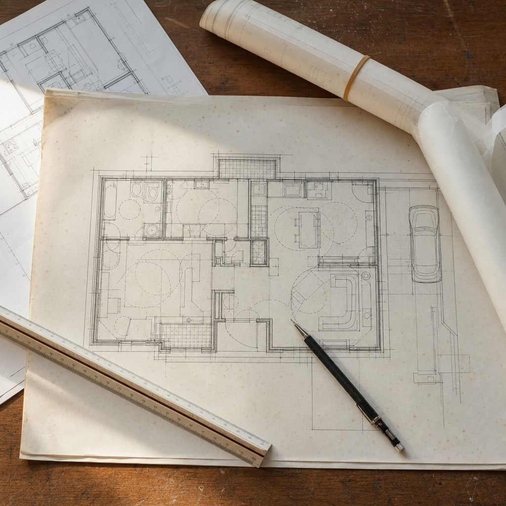
Code-mandated accessible clear floor spaces and maneuvering dimensions are required at virtually every stage of Alberta residential drafting and construction. These accessible planning fundamentals, governed in Alberta by the National Building Code - 2023 Alberta Edition (NBC(AE)), are both frequent sources of plan-review redlines and recurring jobsite complications if omitted or executed imprecisely.
Dimensioning Clear Floor Spaces for NBC(AE) Part 9 Fixtures and Controls: Detailed Sheet Conventions and Redline Triggers
On Alberta residential permit plans, clear floor space requirements for fixtures and controls as detailed in NBC(AE) Sections 9.5.3.11 to 9.5.3.14 must be unambiguously dimensioned and called out. These quantifiable requirements govern virtually all fixtures within bathrooms, kitchens, and laundry areas in Part 9 projects.
Clear Floor Spaces: Specific Dimensional Mandates and Drawing Standards
- Water Closets (9.5.3.11): CBC(AE) mandates a minimum clear floor space of 750 mm in front of the water closet, with a minimum width of 900 mm centered on the fixture. This zone must be unobstructed by cabinetry, towel bars, or vanity projections.
- Lavatories (9.5.3.12): The clear floor space in front of each lavatory (sink) must be at least 750 mm deep and 900 mm wide (centered on the fixture).
- Bathtubs and Showers (9.5.3.13): A minimum of 750 mm clear depth in front of the entrance and a 900 mm minimum width is required for code conformity.
- Kitchens (9.5.3.14): Kitchen work aisles must provide a 900 mm minimum clear width; if passageways are required between fixed counters or islands, a 1,200 mm minimum clear width is mandated for passageways suitable for accessible routes.
Each of these requirements must be dimensioned clearly on floor plans-both in new builds and major renovations-to satisfy municipal plan reviewers and on-site building inspectors.
Dimensioning and Annotation Conventions on Drawings
- Dimension Lines and Labels: Directly annotate the clear spaces on plan sheets, using continuous dimension strings and bubbles. Standard callouts include “750 mm clear floor space in front of W.C. (NBC(AE) 9.5.3.11)” or “900 mm clearance, centered” for lavatories.
- Code Reference Notes: Add a general plan note such as “All fixture clearances to comply with NBC(AE) 9.5.3.11-14” near the proposed fixture group. For example, callout leader lines may state, “Clear floor space - see NBC(AE) 9.5.3.12”.
- Enlarged Toilet Room Details: On large or spatially complex toilet rooms, provide an enlarged plan inset (e.g., scale 1:20) with clearance zones hatched and tightly dimensioned. Identify potential issues, such as:
- Recessed toilet paper holders
- Clearance for swing-out doors adjacent to clear floor spaces
- Vanity side cabinets impinging on 900 mm wide required zones
Addressing Common Permit Redlines Related to Obstructions and Layouts
Plan examiners will frequently issue redlines for overlooked or misunderstood clearance requirements:
- “Revise layout to provide the required 750 mm clear floor space in front of the water closet as per NBC(AE) 9.5.3.11” - commonly triggered by wall-proximate toilets, fixtures installed behind swinging doors, or floor-mounted heating grilles placed in the clearance zone.
- “Ensure no encroachments into the 900 mm clear width centered on lavatory; adjust adjacent cabinetry accordingly” - frequent with floating vanities with side drawers or bump-outs.
- “Increase kitchen work aisle width to meet the 900 mm minimum requirement specified in NBC(AE) 9.5.3.14” - particularly prevalent in galley kitchens or where fridges stand opposite counters.
Specific Fixture Dimensions, Ratings, and Noteworthy Details
- Water Closet Seat Height: 400-460 mm A.F.F. (Above Finished Floor)
- Lavatory Rim Height: Maximum 865 mm A.F.F.
- Bathtub/Showers: Slip-resistant surfaces (per NBC(AE) 9.5.3.13), with grab bars rated for a minimum 1.3 kN load.
- Cabinet Hardware: Operable with a closed fist (lever handles recommended), facilitating one-handed operation per best practice, though not always specifically referenced in Part 9.
Effectively, on Alberta permit plans, every clear floor space must be both shown and dimensioned; “by intent” or notional compliance is a reliable cause of plan redlines and on-site accessibility failures.
Delineating Turning Radii and T-Turns: Dimensioning for Compliance with NBC(AE) 9.5.3.5 and Adjacent Elements
Turning spaces, whether 1,525 mm diameter circles or T-shaped layouts (NBC(AE) 9.5.3.5), are central for wheelchair maneuvering in all accessible dwelling design. Correct graphical depiction and measurement from finish face to finish face-not from wall centerlines or rough framing-are critical, as in-field tolerances make these dimensions tight.
Turning Space Representation and Dimensioning Strategies
- Circular Turning Space: Draw a 1,525 mm (60") dashed or solid line circle, typically in main bathroom floors, entries, or unit core living spaces. Annotate as “1,525 mm turning radius (NBC(AE) 9.5.3.5)” with dimension chain to nearest obstruction (counter, wall, cabinet toe-kick, or closet front).
- T-Shaped Turning Space: Where a full circle does not fit (e.g., narrow corridors), depict a T-shaped layout nested within a 1,525 mm × 1,525 mm square, arms and base at minimum 915 mm widths. Especially useful for bedrooms with built-ins or L-shaped kitchens.
- Measurement Convention: All turning space dimensions must be within finished wall/furniture faces-not rough structural lines, and with allowances for wall finishes, baseboards, and door frames.
Interaction with Door Swings and Built-In Elements
- Door Swings: Show door swing arcs in plan, ensuring turning space is fully unobstructed even when doors are open. Potential conflicts arise where outswing doors overlap with required clearance-annotate:
- “Door swing not to encroach upon required turning space. Relocate or modify as required (NBC(AE) 9.5.3.5).”
- Built-Ins & Protrusions: Note deep base cabinets, shelves, or radiators that could project into maneuvering zones. On plans, label with leaders: “Maintain 1,525 mm clear diameter free of built-in encroachment” and cross-reference to enlarged details if tight.
Detail Conventions, Symbols, and Annotations
- Symbols: Employ a standard turning space symbol (shaded circle or T) with a key in the drawing legend; use hatching for overlapping clearances.
- Detail Call-Outs: Reference enlarged plans (e.g., “See Detail 3/A-502”) if intersection with door hardware, cabinetry, or sloped flooring is a risk.
- Material Notes: Within turning spaces, specify “Floor finish to be firm, friction coefficient >0.6, slip-resistant (NBC(AE) 9.5.3.7).”
Additional Dimensions and Clearances
- Door Openings: Minimum clear width is 860 mm (per NBC(AE) 9.5.3.1), but doors serving turning spaces should aim for 900 mm rough frame minimum to allow hardware clearances and framing tolerances.
- Maneuvering Clearances: For doors:
- Pull side: 1,500 mm (perpendicular) × 600 mm (latch-side) minimum
- Push side: 1,200 mm × 300 mm at a minimum (per NBC(AE) 9.5.3.6)
Failure to clearly dimension and coordinate turning radii relative to doors, millwork, and built-in obstructions remains a common trigger for plan-review comments such as: “Revise entry/bedroom to provide compliant 1,525 mm turning space clear of swing and built-ins; see NBC(AE) 9.5.3.5." On site, improper documentation leads to field-modified millwork, re-hanging of doors, and costly shimming.
Accessible Route Continuity and Doorway Clearances: Drawing, Sectioning, and Detailing for Complete Compliance
Accessible route continuity across Alberta residential projects, from main entries to interior rooms, requires each door, corridor, and threshold to meet minimum clear opening and maneuvering space standards as outlined in NBC(AE) 9.5.3.4 and 9.5.3.7. Plan reviewers and site inspectors are increasingly vigilant regarding how these are drawn, dimensioned, and detailed-and frequently redline even minor omissions.
Clear Door Widths and Latch-Side Maneuvering Dimensions
- Required Door Clear Width: Section 9.5.3.4 requires 850 mm minimum clear width (from edge of fully open door to stop on latch side). This is exclusive of hardware provided lever handles or panic bars are above 900 mm and below 1,100 mm A.F.F.; otherwise, clear width is measured from hardware face.
- Maneuvering Clearances (per 9.5.3.7):
- Front Approach (Pull Side): 1,500 mm × 600 mm beyond latch side
- Front Approach (Push Side): 1,200 mm × 300 mm
- Hinge/Latch-Side Approaches use same dimensions as above for perpendicular and side clearance
- Dimension on plan and provide enlarged detail at key entries.
Threshold Detailing: Plans, Sections, and Enlargements
- Threshold Height: 13 mm maximum above finished floor, beveled (NBC(AE) 9.5.3.7).
- Elevations and wall sections must depict and label the threshold profile-callout example: “Threshold to be 13 mm max, beveled/notched, in contrasting colour. See DT-401.”
- For renovation projects, mark “Maintain transition ≤13 mm; provide mortar ramp or reducer strip as required.”
Enlarged Details and Schedules for Clarity
- Plan Enlargements: Where space is limited (e.g., corridors serving multiple rooms), provide at least one enlarged plan at 1:20 scale showing all critical access elements: door swings, hardware positions, transition strips, and maneuvering zones.
- Door Schedules: List width (“850 mm clear opening”), hardware type, height (lever handles at 900-1,100 mm), threshold type, and material. Include columns for “Accessible/Rated Y/N” and cross-reference drawing details.
Typical Plan-Review Comments and Field Coordination Notes
- “Door opening insufficient-minimum clear width is 850 mm; adjust rough frame or verify swing.”
- “Missing latch-side maneuvering clearance; revise layout to provide unobstructed approach in compliance with NBC(AE) 9.5.3.7.”
- “Threshold exceeds 13 mm; detail required for transition-provide cross-section and material callout.”
Material Specifications
- Thresholds and Floor Surfaces: Non-slip; preferred slip rating >0.6. Mortar or metal-reduced thresholds recommended for durability and minimal profile.
- Door Hardware: Lever type, D-shaped pulls, or push/pull plates. Stainless steel or anodized aluminum typical. All accessible hardware to permit operation with a closed fist.
Plan sheets, sections, and details must work in tandem to guarantee field clarity-disjointed references or ambiguous dimensions are a major source of failed inspections and costly on-site modifications.
Integrating Accessibility Notes, Legends, and Code Call-Outs in Permit Drawing Sets for Plan Review and Construction
Accessibility compliance in Alberta is not achieved through plan graphics alone. Efficient permit sets integrate accessibility into their organization, notation, and detailing, ensuring that intent is both reviewed and executed correctly by contractors and trades on site.
Sheet Organization: Locating and Communicating Accessibility Information
- General Notes Sheet (often G-001):
- Start with a comprehensive accessibility declaration such as: “All work to comply with National Building Code - 2023 Alberta Edition (NBC(AE)) and applicable STANDATA bulletins.”
- List project-wide accessibility requirements: e.g., “All main entries, routes, and sanitary facilities to meet NBC(AE) 9.5.3.x.”
- Include a legend for accessibility symbols-use standard icons such as wheelchair motif, hatched maneuvering zones, or highlighted clear floor spaces.
- Discipline Sheets (A for Architecture, S for Structure): Place discipline-specific accessibility notes on the first sheet of each discipline (e.g., “A-001”), especially for projects with separated drawing sets.
Standardized Notes and Direct Code References
- General Accessibility Notes: Examples commonly used:
- “All accessible path-of-travel requirements to NBC(AE) 9.5.3.4, 9.5.3.7.”
- “Provide barrier-free circulation to and within all principal rooms and sanitary facilities per NBC(AE) 9.5.3.5.”
- “Door hardware to be accessible per NBC(AE) 9.5.3.7, lever type, 900-1,100 mm above finished floor.”
- Direct Drawings Call-Outs: For fixtures, corridors, doorways, etc.-label directly on plans: “Clearance per NBC(AE) 9.5.3.11” with leader to the dimension.
Specifying Accessible Components on Drawings
- Doors:
- Dimension all required clear widths; indicate automatic door operator if required (“Auto Door Opener as per NBC(AE) 3.8.3.3”).
- Note all accessible door hardware on schedule (“Lever handle hardware at 900-1,100 mm AFF, per NBC(AE) 9.5.3.7”).
- Washroom Details:
- Show all clearance circles/boxes in plan (e.g., “1,525 mm turning circle, 900 mm x 750 mm clearance in front of fixture, all as per NBC(AE) 9.5.3.13”).
- Dimension and draw grab bar locations, labeled as “Grab bar, 1.3 kN rated, 840-920 mm AFF”.
- Kitchens: Annotate work aisle and passageway widths (“Minimum 900 mm/1,200 mm, see NBC(AE) 9.5.3.14”) and specify accessible appliances if required (“Controls operable with closed fist”).
Call-Outs, Legends, and Cross-Referencing Conventions
- Keynotes: Use number-letter system (e.g., K1, D3), referenced to a schedule tied to code sections (e.g., “K6: Accessible Kitchen Work Aisle, 900 mm min, NBC(AE) 9.5.3.14”).
- Reference Flags: Standard section/elevation bubbles (“4/A502” for detail 4 on A502), with an adjacent legend near the title block for at-a-glance navigation.
Anticipating and Preventing Redlines in Plan Review
- “Show accessible route on plan-does not visually connect all required spaces” is a common correction.
- “Redline clearance not dimensioned; provide enlarged detail and material designation”.
- “List door operator location and model on schedule or clarify hardware height/location”.
Embedding code references and explicit notations on every sheet supports both municipal plan reviewers and jobsite contractors-reducing RFI backlogs, change orders, and work stoppages due to code nonconformity.
Addressing Real-World Accessibility Challenges On Site: Construction Tolerances, Verification, and the RFI Pipeline
No matter the clarity of plans, site realities demand rigorous verification of accessibility dimensions, close oversight of construction tolerances, and responsive RFI and shop drawing review workflows to correct discrepancies before they translate to costly rework or accessibility failures.
Construction Tolerances: Allowances, “Verify in Field,” and In-Field Records
- Design Allowances: Alberta drafters must engineer a small buffer above legal minima. For example, for a required 1,525 mm turning radius, permit 1,550 mm on plan to account for framing/finish slip; for an 850 mm required door opening, rough frame to at least 910 mm (36") for standard practice.
- ”VIF”-Verify in Field: Mark all key accessibility dimensions with VIF notes (e.g., “850 mm min clear opening VIF”) and require confirmation at layout, framing, and post-install stages.
- Site Records: Maintain on-site logs of as-built dimensions, especially at doorways, corridors, ramp approaches, and fixture clearances. These records are often required for final occupancy approval and Apple-to-Apple comparison with permit sets.
Managing RFIs and Shop Drawing Reviews for Accessibility Gaps
- RFIs for Conflicts or Ambiguities: Field teams encountering ambiguous site/run dimensions (“missing 100 mm at lavatory due to misplaced wall framing” or “closet door swing encroaches required maneuvering circle”) must submit RFIs referencing the relevant NBC(AE) section and requesting official variance approval or layout revision.
- Shop Drawing Oversight: All shop drawings for custom millwork, prefabricated bathrooms, or specialty hardware must show and dimension compliance with accessibility requirements (e.g., “Pulls to be installed at 1,000 mm above F.F., door clear opening min 850 mm”). Reviewer stamps should specifically list: “Reviewed for accessibility - coordinated with permit plan dimensioned clearances.”
- Coordination Meetings: Regular OAC (Owner-Architect-Contractor) site walks to “spot check” barrier-free clearances versus plans. Checklists should begin with: “All doorways (main entry, bedroom, washrooms, kitchen), check clear opening against permit set.”
Key Alberta Code References and Exceedance by Local Amendments
- Alberta Building Code (2023), Section 3.8: Door openings (3.8.3.3), corridor widths (min 1,100 mm), and ramp slopes (1:12, 900 mm min width), each enforceable in municipal review.
- City of Calgary Access Design Standards: On many multi-family or mixed-use projects, these go above provincial minima-document in both plan notes and in-site checklists.
Statuses and Examples of Plan-Review Redlines
- “Ensure all doorways provide a minimum clear width of 850 mm as per NBC(AE) 3.8.3.3” if as-built dimensions are found to be below code due to jamb thickness or mislocated stud walls.
- “Edit corridor framing to maintain ≥1,100 mm clear (clear of baseboards) - required for barrier-free units.”
Effective Drawing-Sheet Communication for Jobsite Troubleshooting
- Durable Notation and Legend: Accessible features are often layered in dedicated CAD layers (e.g., “A-ACCESS” in AutoCAD), plotted in contrasting colour or greyscale for clarity.
- Enlarged Details: All known “tight” transitions-corner doors, alcove bathrooms, or secondary entries-should be shown at large scale (1:10), with dimension strings and compliance references visible on sheet.
On-Site Tolerance, Final Dimensions, and Material Specifications
- Doors: As constructed, 850 mm minimum clear. Caution for overbuilt jambs or thick weather seals.
- Corridors: Confirm 1,100 mm clear (baseboard to baseboard).
- Ramps: Maximum slope 1:12 (8.33%), minimum 900 mm clear. Guard and handrail height 865-965 mm, grip diameter 30-40 mm, per code.
- Flooring: Surfaces must remain “firm, stable, slip-resistant” post-trade install. Watch for tile transitions at thresholds and entries.
Project success in Alberta residential permits is measured as much by close-out lists and inspection sign-off as by plan approval. Tightly controlled dimensioning, continuous verification, and crystal-clear notation at every drawing and construction phase are the foundation of true accessibility in built projects.
With Kingsway Drafting & Design, every Alberta residential permit plan is meticulously detailed to ensure accessible compliance-right from drawing sheet to site completion.