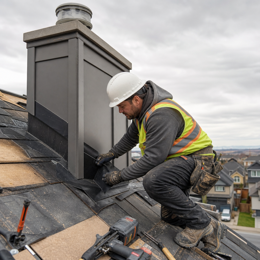
Water infiltration at roof penetrations is a leading cause of building envelope failure in Alberta residential construction. Meticulously drafted, code-compliant flashing details for chimneys and vent stacks are fundamental for both passing municipal plan reviews and ensuring in-field buildability. The Alberta Building Code (ABC), particularly Section 9.26.4 and related articles, prescribes precise flashing overlaps, embedments, counter-flashing methods, and saddle (cricket) implementations. Translating these prescriptive rules into clear, buildable documentation requires in-depth understanding-from graphic conventions on sheets to explicit dimensioning, materials selection, and the proactive handling of typical Authority Having Jurisdiction (AHJ) redlines. Deep technical integration at the drafting stage is the only way to achieve compliant, review-ready plan sets and robust, durable construction on Alberta job sites.
Translating Alberta Building Code Section 9.26.4 Into Actionable Chimney and Vent Stack Flashing Requirements on Plan Sets
Specifying Chimney & Vent Flashing: Direct Code References for Drawings and Notes
The primary ABC requirements governing flashing at chimneys and vent stacks appear in Section 9.26.4:
- ABC 9.26.4.4, Intersection of Shingle Roofs and Masonry: Mandates that intersections between shingle roofs and masonry walls or chimneys be protected with both base flashing (step flashing) and counter flashing. Counter flashing must be embedded at least 25 mm into the masonry, extend a minimum of 150 mm down the masonry face, and overlap the lower flashing by at least 100 mm. Flashing along sloped roofs requires step (or stepped) configuration, with a head lap of no less than 75 mm in both lower and counter flashing.
- ABC 9.26.4.8, Chimney Saddles: Chimney saddles (also called crickets) are required on the upper side of any chimney over 750 mm (approx. 30 in.) wide, upslope. Saddle must be covered with sheet metal or robust roofing material and flashed at all intersections with roof and chimney. Omission is only permitted if large-format sheet-metal flashing up the chimney meets specified cover heights.
- ABC 9.26.4.9, Roof Penetrations: Joints between pipes/ducts and roof must be flashed, watertight, and use a rectangular base plate at least 500 mm by 500 mm. The upstand (“sleeve”) must extend 150 mm minimum above finished roof.
To ensure these requirements are not missed during plan reviews, include explicit drawing notes that directly cite these ABC clauses. For example:
- “ALL CHIMNEY FLASHINGS TO BE INSTALLED IN ACCORDANCE WITH ABC 9.26.4.4: COUNTER FLASHING TO BE 25 mm MIN. EMBEDDED INTO MASONRY, 150 mm MIN. DOWN MASONRY, 100 mm MIN. OVERLAP TO BASE FLASHING.”
- “CHIMNEY SADDLES (CRICKETS) REQUIRED UPSLOPE OF ANY CHIMNEY >750 mm WIDTH, SADDLE COVERED IN SHEET METAL/RIGID ROOF MATERIAL (ABC 9.26.4.8)”
- “ROOF PENETRATIONS (VENT PIPES) TO BE FLASHED W/500×500 mm METAL BASE, SLEEVE 150 mm ABOVE ROOF (ABC 9.26.4.9).”
Redline Triggers and Plan Review Pitfalls: What ABC Compliance Looks Like at Review
Alberta municipal reviewers consistently flag:
- “No specific chimney flashing details, insert ABC-referenced section detail with dimensions.”
- “Missing or non-compliant cricket for chimney width >750 mm; provide saddle detail per ABC 9.26.4.8.”
- “Vent stack flashing detail does not show required flange/sleeve dimensions-minimum 500×500 mm base, 150 mm upstand.”
Generic details or absence of detail references on the roof plan provoke redlines and delays. Embedding ABC clause references (“Flashing per ABC 9.26.4.4”) and dimensioned call-outs in plan notes is now standard practice for Alberta residential sets.
Drawing Conventions and Integration: From Roof Plan to Section Details
- Roof Plan Sheet: “Chimney-see Detail 5/A5.1: Step and Counter Flashing at Masonry Chimney.”
-
Detail Sheet:
“Counter flashing: 0.41 mm (30 ga.) min. galvanized steel, 150 mm down masonry, embed 25 mm, overlap step flashing 100 mm min. Step flashing: 100 mm up vertical, 100 mm on roof, lapped 75 mm min. at each course.”
- General Notes: “All flashing installation to meet minimum gauge, width, and embedment as per ABC 9.26.4.4, 9.26.4.8, 9.26.4.9.”
Explicit clause references, dimensioned call-outs, and tailored flashings for each intersection type are essential to pass municipal review and prevent ambiguous on-site interpretations.
Summary Table: Critical ABC-Driven Flashing Minimums for Plan Sheets
| Location/Element | Gauge | Dimensions | ABC Reference |
|---|---|---|---|
| Counter Flashing @ Masonry | 30 ga./0.41 mm | 25 mm embed, 150 mm down, 100 mm overlap | 9.26.4.4 |
| Step Flashing | 30 ga./0.41 mm | 100 mm up, 100 mm out, 75 mm lap | 9.26.4.4 |
| Cricket/Saddle | 24 ga./0.56 mm | Per roof/wall, saddle for >750 mm | 9.26.4.8 |
| Vent Stack Flashing | 26 ga./0.46 mm | 500 x 500 mm base, 150 mm sleeve up | 9.26.4.9 |
Precision Detailing: Dimensioning, Overlaps, and Graphical Standards for Buildable Step & Counter Flashing in Alberta Roof Details
Overlaps, Stepping, and Integration: How Plan Details Must Specify Each Sequence
Plan review frequently sees redlines for insufficient flashing lapping, missing crickets, or improper integration with water-resistive barriers (WRB). When drawing flashing at chimneys or at roof-wall junctions, Alberta standards-supported by the Alberta Roofing Contractors Association and enforced by AHJs-specify each step:
- Step Flashing: Each piece is 0.41 mm (30 ga.) galvanized steel, minimum 100 mm vertical leg (up wall) and 100 mm horizontal leg (over shingle/roof deck). Each piece overlaps the course below by 75 mm.
- Counter Flashing: Also 30 ga. min.; must extend downward 150 mm minimum (ABC 9.26.4.4), overlap the top of step flashing 100 mm, and be embedded 25 mm into masonry. Horizontal and vertical laps must both be detailed in stepped conditions.
- Kick-Out Flashing: At the base of step/counter flashing runs, a kick-out diverter must be shown and dimensioned (typically 100 mm horizontally out from wall) to ensure roof water cannot miss the eavestrough and run behind wall cladding. Its absence is a universal redline.
Standard Sheet Graphics: Communicating Flashing on Alberta Plan Sets
Plan views (A1 or A2 series sheets) call out flashing details at all roof intersections. Each reference points to a numbered detail on the building section or detail sheet (“Detail 8/A7.4: Typical Step Flashing at House Wall”). Section drawings must layer roofing, WRB, step flashing, and counter flashing in true sequence (bottom-up), dimension each leg, and label head laps and overlaps.
- Dimension lines: 100 mm at vertical and horizontal legs, 75 mm lap annotation at overlap.
- Material tags: “30 GA GALV. STL. FLASHING; PROVIDE KICK-OUT FLASHING AT BASE.”
- Notes: “INSTALLATION PER ABC 9.26.4.4.”
Drawn sections must show the step/counter relationship, lapping above course below and under lifted shingle. For masonry chimneys, the embedded counter flashing groove must be dimensioned and cross-hatched for clarity.
Kick-Outs, Crickets, and Plan Review Stops: Getting the Details Accepted
AHJs and warranty inspectors often flag missing kick-out flashing, lack of cricket logic (for chimneys >750 mm wide-see ABC 9.26.4.8), or insufficient upstand/overlap. Kick-out flashings must be graphically shown on section elevations and their fabricated dimension (min. 100 mm extension) labeled, typically with a detail note:
- “KICK-OUT FLASHING: 0.41 MM GALV. STL., EXTENDS 100 MM OUT FROM WALL TERMINATION, DIRECTS WATER INTO EAVESTROUGH BELOW.”
Similarly, crickets must be drawn-on both plan and section-when required, with notation for:
- “SADDLE TO MATCH OR EXCEED MAIN ROOF SLOPE, COVER WITH 24-GA. GALVANIZED STEEL, FLASH ALL INTERSECTIONS, SEE DETAIL 9/A7.5.”
Material and Dimension Examples: Best-Practices Table
| Condition | Material & Gauge | Dimensions | Critical Overlap |
|---|---|---|---|
| Step Flashing, Asphalt Shingles | 30 ga. galvanized steel | 100 mm vertical, 100 mm horizontal | 75 mm overlap course to course |
| Counter Flashing, Masonry Chimney | 30 ga. galvanized steel or 16 oz. copper | 150 mm down face, 25 mm embed | 100 mm overlap to step flashing |
| Kick-Out Flashing | 30 ga. galvanized steel | 100 mm extension | N/A; base of step/counter run |
| Chimney Cricket | 24 ga. galvanized steel | Slope matches roof, 150 mm up face | Lap and flash as per ABC 9.26.4.8 |
Material Specifications and Jobsite Call-Outs: ABC-Compliant Integration on Detail Sheets and In Project Manuals
Flashing & Sealant Material Requirements: Project Manual and Drawing Sheet Integration
The ABC and Alberta warranty standards require flashing materials not only to hit minimum dimensions but also to meet minimum material gauge and finish. Call-outs must specify:
- Galvanized steel: 0.41 mm (30 ga.) minimum; 0.46 mm (26 ga.) recommended for vent bases.
- Copper: 0.56 mm (16 oz.) minimum.
- Aluminum: 0.60 mm (22 ga.) minimum.
- Finish: Baked enamel or mill-galvanized/prefinished stock per project manual Section 07 62 00 (Sheet Metal Flashing and Trim).
Detail sheets must indicate: “ALL FLASHING TO BE 0.41 mm GALVANIZED STEEL MINIMUM, PREFINISHED, ALL JOINTS SEALED WITH POLYURETHANE SEALANT (ASTM C920), COLOUR TO MATCH ADJACENT CLADDING.” The project manual specification for sealants should reference ABC Section 9.27.4, requiring non-hardening, WRB-compatible products conforming to ASTM C834, C920, or C1184.
Integrated Jobsite Install Notes and Typical Plan-Review Comments
Common AHJ comments on submitted plans include:
- “Sealant product not specified; must show ASTM number and substrate compatibility for all sheet metal.”
- “Flashing terminates without end-dam; indicate 25 mm upstanding tab at horizontal cut-off.”
- “Project manual/spec sheet does not indicate WRB-flashing-lap sequence. Provide installation diagram/note.”
To ensure inspector and contractor clarity, use callouts such as:
- “INSTALL FLASHING SLOPED MIN. 6% AWAY FROM STRUCTURE; PROVIDE 25 mm END-DAM AT ALL TERMINATIONS.”
- “SEAL ALL SHEET METAL JOINTS WITH EXTERIOR-GRADE, PAINTABLE POLYURETHANE SEALANT, ASTM C920, COLOUR TO MATCH.”
Plan details must also show in cross-section the correct sequence: deck>ice-and-water>step flashing in shingle-lap pattern>counter flashing, all lapped above course below.
Critical Material, Gauge, and Installation Dimensions at a Glance
| Component | Minimum Thickness | Installation Highlight |
|---|---|---|
| Step/Counter Flashing | 0.41 mm galvanneal (30 ga.) | Embed 25 mm in mortar joint, lap 100 mm to step flashing, 2%-6% slope away from masonry |
| Vent Pipe Base Flashing | 0.46 mm galvanneal (26 ga.) | 500 × 500 mm plate, sleeve 150 mm upstand above roof |
| Sealant at Joints | Conform to ASTM C920, C834, C1184 | Non-hardening, UV-stable, match adjacent cladding |
| End-Dam | Same as flashing | 25 mm upstand at flash terminations |
Addressing Roof Drainage: Chimney Crickets (Saddles) and Vent Stack Base Flashings on Alberta Plans
Cricket and Saddle Design: Trigger Points and Dimension Standards per ABC 9.26.4.8
Roof drainage at chimneys is a persistent plan review concern. Alberta code, section 9.26.4.8, is explicit:
- Chimney saddles (crickets) are required where the upper side width of a chimney is greater than 750 mm on a sloped roof.
- Saddles must be flashed to the chimney and roof with same material standards as field roof-often 24 ga. galvanized steel (thicker for increased durability around wide, water-exposed penetrations).
- Saddle slope must match or exceed adjacent roof slope for effective drainage.
- All flashing and counter flashing at these intersections to match the 150 mm down-face, 25 mm embedded, 100 mm overlap standards (ABC 9.26.4.8 references back to 9.26.4.4).
- Exception: For chimneys over 750 mm wide, where a continuous metal flashing wraps up the chimney to at least 1/6 the chimney width (but never less than 150 mm).
A plan sheet must show the cricket on both roof and section sheets, called out clearly:
- “PROVIDE CHIMNEY CRICKET (SADDLE) W/24 GA GALVANIZED STEEL, SLOPE MATCHING ADJ. ROOF SLOPE, FLASH & COUNTERFLASH ALL JUNCTIONS, SEE DETAIL 7/A7.2.”
Dimension lines should indicate “MIN. WIDTH: 750 mm-CRICKET REQUIRED” and arrow the change in roof plane. Cricket flashing wrapping up onto the chimney body is dimensioned “MIN. 150 mm UP VERTICAL.” Discontinuous or generic representation invariably leads to plan review comments for “full cricket and flashing detail per ABC 9.26.4.8.”
Vent Stack Base Flashings: Achieving the Code-Mandated Waterproofing Envelope
Vent stack flashing must achieve both water shedding and weatherproofing. ABC 9.26.4.9 prescribes:
- Flashing base: 500 mm x 500 mm minimum rectangle, 26 ga. (0.46 mm) galvanneal or better.
- Sleeve “upstand” extension: At least 150 mm above the finished roof plane at all points, with a formed collar sealed to the vent with compatible, UV-stable exterior-grade sealant.
- On sloped roofs: Flashing flange must project no less than 125 mm from pipe/duct edge at all points.
- On flat roofs: 250 mm projection at all points.
Plans must call out both dimensional requirements and material:
- “VENT FLASHING-0.46 mm GALVANNEAL, BASE PLATE 500 mm × 500 mm MIN., SLEEVE EXTENDS 150 mm ABOVE FIN. ROOF, FLANGE EXTENDS 125 mm MIN. (SLOPED ROOF).”
Section details must depict the WRB and shingle/sheet integration, the upstand, collar caulking, and dimensioned flange extents.
Sample Section Call-Out for Chimney Cricket and Vent Base
Sheet A7, Detail 7/A7.2 (Cricket at Chimney):
- “1. SADDLE SLOPED TO MATCH ADJACENT ROOF PITCH; 24 GA GALVANIZED SHEET METAL COVER.”
- “2. CRICKET FLASHING CONT. UP CHIMNEY MIN. 150 mm; STEP AND COUNTER FLASHING EMBEDDED 25 mm, OVERLAP AS ABC 9.26.4.4.”
- “3. SHINGLES OVER CRICKET BARRIER; ALL FLASHINGS TERMINATED WITH 25 mm END-DAMS.”
- “4. ALL JUNCTIONS CAULKED W/EXTERIOR SEALANT (SEE SPEC SECTION 07 92 00).”
Proactive Plan Review: Common Alberta AHJ Redlines, Strategic Documentation, and Standardized Detail Libraries
Frequent Redlines by Alberta Authorities Having Jurisdiction (AHJ)
Instances most likely to provoke plan review comments include:
- Flashing does not extend up behind WRB minimum 50 mm (per NBC(AE) 9.27.3.8.(4)(a)); extend flashing up wall/vertical assembly and reference ABC directly.
- Overlap < 10 mm to building element below (NBC(AE) 9.27.3.8.(4)(d)); all horizontal flashings to lap below a min. 10 mm, with a 5 mm outward drip edge (9.27.3.8.(4)(e)).
- End-dams missing on horizontal flashings (NBC(AE) 9.27.3.8.(4)(c)); all cut-ends must turn up min. 25 mm, graphically shown on section/elevation.
- Material incompatibility (NBC(AE) 9.27.3.8.(4)(b)); specify all flashings as galvanneal, copper, or color-aluminum per code thicknesses for the climate/exposure described.
- Poor integration of flashing with adjacent WRB; detail sequence in both plan note and installation sequence drawing with cross-references to section/elevation.
To expedite review, all typical chimney and vent stack details should be pre-annotated with the relevant code citations (“MIN. 50 mm BEHIND WRB PER 9.27.3.8.(4)(a), DRIP EDGE PER 9.27.3.8.(4)(e), END-DAMS MIN. 25 mm PER 9.27.3.8.(4)(c)”) directly in the detail keynotes.
Strategic Documentation for Plan Review Success
Consistent, high-detail documentation minimizes review cycles. AHJ-preferred strategies include:
- Provide detail sheet cross-references for every flash and penetration on the roof plan (e.g., “STEP/COUNTER FLASHING AT CHIMNEY, SEE DETAIL 4/A8.1”).
- Cite drawings with both dimensions and materials (“0.41 mm GALVANIZED STL., 150 mm DOWN FACE, 25 mm EMBED”) and explicit code cross-references (e.g., “PER NBC(AE) 9.27.3.8.(4)(a)-(e)”).
- List installation sequence, especially at WRB and saddle intersections, in both elevation and specification (e.g., “STEP FLASHING INTEGRATED W/ICE & WATER SHIELD, UNDER SHINGLE COURSE, LAP MIN. 75 mm.”).
- Attach manufacturer cut sheets or diagrams for proprietary or preformed flashing assemblies, to preempt AHJ requests for compliance substantiation.
Developing a Standardized Chimney and Vent Flashing Detail Library
Establishing an internal library of standard, code-compliant flashing details allows for consistent documentation and rapid deployment on all Alberta projects.
- Library details should show: All minimum dimensions, gauge and finish callouts, code references, WRB-flash integration sequence, and end-dam/overlap notation.
- Annotations: Use a standardized system for material callouts (“STL1: 0.41 mm galvanneal, STL2: 0.56 mm galv. cricket” etc.)
- Regular updating: Code cycles, new interpretations via Alberta Building STANDATA, municipal reviews, and warranty provider bulletins must prompt updates to all details in use.
References from code-such as “Upward extension: min. 50 mm behind WRB (NBC(AE) 9.27.3.8.(4)(a)); Downward overlap: min. 10 mm with 5 mm drip edge (9.27.3.8.(4)(d)-(e)); End-dam: min. 25 mm or code-driven calculation (9.27.3.8.(4)(c))”-should be included on every template to provide clarity in both the plan review and site implementation processes.
Dimensions, Gauges, and Ratings Required in Alberta (Summary Table)
| Flashing Application | Gauge/Spec | Dimension | ABC/NBC(AE) Reference |
|---|---|---|---|
| Step Flashing | 0.41 mm (30 ga.) galv. | 100 mm up, 100 mm out, 75 mm lap | 9.26.4.4 |
| Counter Flashing (Masonry) | 0.41 mm (30 ga.) galv. | 25 mm embed, 150 mm down, 100 mm lap | 9.26.4.4 |
| Chimney Cricket | 0.56 mm (24 ga.) galv. | For chimneys >750 mm; 150 mm up vertical | 9.26.4.8 |
| Vent Base Flashing | 0.46 mm (26 ga.) galv. | 500 × 500 mm base, 150 mm sleeve upstand | 9.26.4.9 |
| Horizontal Flashing End-Dams | Match field flashing | 25 mm upstand min. | 9.27.3.8.(4)(c) |
Conclusion: Alberta-Focused Flashing Details-The Core of Robust Residential Envelopes
Code-compliant and buildable chimney and vent stack flashing details are only achieved by integrating Alberta Building Code Section 9.26.4 and related clauses directly into every plan sheet, section, and specification. Critical dimensions-25 mm embedment, 100 mm overlaps, 150 mm down faces, 750 mm+ crickets, and WRB-flash integration-are not optional. Standardized detail libraries, strategic plan documentation, and consistent material callouts not only ensure rapid plan approval, but also extend the service life of every residential project’s roof and envelope. With clear graphical convention, layered detailing, and clause-referenced notes, plan sets produced for Alberta homes, infills, and developments will withstand both scrutiny in the permit office and decades of Alberta weather.
Kingsway Drafting & Design brings this level of technical rigour and local code expertise to every Alberta residential project.