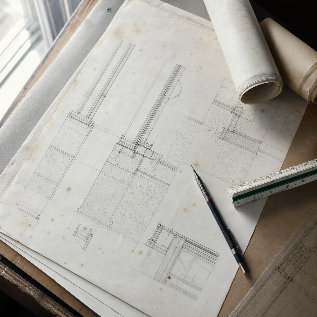
Wood-frame walls in Alberta require meticulous foundation connection detailing to comply with the National Building Code - Alberta Edition (NBC(AE)). Plan sheets, dimensioning conventions, call-outs, material specifications, and construction notes must reflect anchorage, treatment, air/vapour continuity, and capillary break standards-each with precise code references, schedules, and revision histories that survive both municipal plan review and field inspection. From specifying a 12.7 mm anchor bolt at 1.7 m o.c., 178 mm embedment (per NBC(AE) 9.23.6.4) to prescriptively tagging PT lumber per CSA O80, code-compliant sill plate connections underpin structural and moisture performance from permit issue to project close-out.
Anchor Bolt and Strapping Requirements: Detailing for ABC Minimum Embedment, Spacing, and Load Transfer
Code-Mandated Anchor Bolt Dimensions, Embedment, and Spacing on Plan Sets
NBC(AE) 2019 and 2023 specify that anchor bolts binding wood sill plates to concrete foundations must measure a minimum of 12.7 mm (1/2") in diameter and penetrate the concrete at least 178 mm (7") (Section 9.23.6.4). Maximum horizontal bolt spacing stands at 1.7 m (5 feet 7 inches). Placement must occur within 0.5 m (19.7 inches) of each foundation end.
Typical architectural drawing conventions include:
- Foundation Plan: Bolt positions symbolized (e.g., black dots with tags such as “A1”), referencing schedules-which read, for example, “Embed anchor bolts min. 178 mm into concrete at 1700 mm o.c. max., 12.7 mm ⌀, positioned within 500 mm of ends.”
- Plan Tag Example: “AB1: 12.7 mm ⌀ x 300 mm L. anchor, ASTM F1554 Grade 36, 178 mm embedment, max. 1700 mm o.c. @ 500 mm from ends. Plate washers per seismic zone if req’d.”
- Schedules and Symbols: Anchor Bolt Schedule with columns for location, size, material grade, embedment, washer type, and special notes (e.g., “PLW1: Plate washer 76 x 76 x 5.8 mm if Sa(0.2) > 0.5”).
Load Path and Seismic Washers: Redlines and On-site Observations
Frequent plan-review redlines focus on:
- Insufficient embedment: Revised note: “Anchor embedded 120 mm-must be 178 mm min. Ref: NBC(AE) 9.23.6.4.”
- Over-spaced anchors: “Re-dimension anchor bolt spacing-shown at 2.0 m o.c., must not exceed 1.7 m per code.”
- Omitted plate washers in seismic design: “Specify plate washers-see NBC(AE), seismic detailing. Add 76 x 76 x 5.8 mm washer call-out on detail.”
Material Specifications and Alberta Amendments
Alberta-specific amendments (referenced through STANDATA variances at alberta.ca) rarely relax anchor bolt embedment, but clarifications often address bolt edge distances to account for curing and consolidation practices in local concrete mixes. All anchor bolts must meet ASTM F1554 Grade 36 (or higher) for tensile strength, with material and compliance tags required for field inspection.
Sill Plate Material Specifications and Call-Outs: Pressure Treatment, Decay, and Termite Control
Code and Standard Requirements for Sill Plate Calling Out on Drawings
Whenever a wood member is in contact with concrete or less than 150 mm above finished grade, NBC(AE) Part 9 (9.3.2.9) requires the use of pressure-treated (PT) or naturally decay-resistant lumber. This is cross-referenced directly in foundation sections and wall details. A sample key note for wall section sheets reads:
- “2x6 PT Sill Plate per CSA O80, AWPA UC4A above/below grade, use hot-dip galvanized fasteners.”
The CSA O80 Series sets the standard for treatment retention and method:
- PT plates at grade (contact with concrete) require at least UC4A treatment, with AWPA label noted on supplier tags.
- Where termites threaten (generally near Lethbridge), all wood members within 450 mm (18") of ground are specified as PT or must use a species naturally resistant to insects and decay.
- Dampproofing separation: Sight-specific notes such as “Provide 0.05 mm poly barrier under non-PT sill plates; typ. at unheated garages.”
Fastener Compatibility and Cross-referencing Material Schedules
Pressure-treatment chemicals attack uncoated mild steel; hence, fasteners must be called out as hot-dip galvanized or stainless steel. Plan legend entries for foundation/wall sheet notes include:
- “Nails/bolts in PT plates: Hot-dip galvanized to ASTM F2329 or stainless steel.”
Material Schedule Tagging and Termite/Decay Protection Zones
Manual plan review often identifies mismatched tags on sill plans-e.g., architectural set calls “2x6 Sill Plate,” but no note on PT treatment, leading to redline comments: “Revise all foundation sill plate call-out to PT per ABC 9.3.2.9 with CSA O80 ref. Confirm on finish schedule.” For new areas of termite risk, inspectors may circle plans or issue field directives: “Specify PT plate throughout crawlspace per termite protection-provide manufacturer documentation.”
Capillary Break and Air Barrier Continuity Detailing: Sill Gasket, Vapour Retarder, and Sheathing Membrane Integration
Sill Gasket and Capillary Break Representation on Details
Section 9.27.2.2 of NBC(AE) establishes a strict requirement for capillary breaks at the exterior wall-usually interpreted in Alberta as calling out a sill gasket under all wood-concrete interfaces. Drawings typically employ a dashed rectangle line, labeled thus:
- “6 mm (1/4") closed-cell foam sill gasket, continuous between PT plate and concrete foundation (capillary break per 9.27.2.2).”
Air and Vapour Barrier Continuity: Drawing Conventions and Checklist Items
Per 9.25.3.3, air barriers must be continuous-shown as a dotted line with a key note:
- “Continuous air barrier from below slab/vapour retarder to exterior sheathing membrane; overlap and seal at sill per manufacturer’s details.”
For vapour retarders, draw with a double-dashed line and a label such as:
- “6 mil poly vapour retarder on warm-in-winter side of wall, sealed to plate and interconnected to floor membrane.”
- “Extend exterior sheathing membrane over plate and seal to foundation; tape all seams per manufacturer. Shown dashed in section, keyed as ‘WBM1.’”
Detailing and Sealing for Air and Water Tightness
Section tags and notes reference elastomeric sealant installed on both the exterior and interior sides of the sill plate. “Apply bead of low-VOC elastomeric sealant compatible with both poly vapour retarder and foam gasket; verify continuity in field insulation inspection.” Discontinuous or missing air/vapour details prompt direct reviewer comments: “Section at wall/foundation transition not clear-revise for continuous air/WRB/VB at sill (ABC 9.25.3.3, 9.27.2.2).”
Foundation Anchor Bolt Schedules and Layout Plans: Dimensioning, Tagging, and Proprietary Hold-Down Coordination
Anchor Bolt Schedules: Layout, Symbol Use, and Checking
Anchor bolts are documented in schedules appearing in the foundation sheet margin or as a standard table block; headings include:
- “Reference/Tag”
- “Bolt Diameter”
- “Material/Grade”
- “Embedment”
- “Spacing”
- “Notes/Special”
- “A1 / 12.7 mm / ASTM F1554 Gr. 36 / 178 mm min. / 1700 mm o.c. max. / c/w plate washer if Sa(0.2)>0.5”
Dimensioning anchor location is critical: tick marks at consistent offsets from wall corners/end conditions are paired with dimensions (e.g., “305 mm max./ 89 mm min. from end of sill plate-see Section 9.23.6.4”). For proprietary hold-downs in engineered walls (Simpson Strong-Tie or equivalent), add a secondary schedule such as:
- “HD1: SST HDU3 pre-engineered hold-down, 4.80 kN capacity, install per manufacturer, coordinate with A1 anchor locations. Do not substitute without written engineer approval.”
Best Practice for Legibility and Cross-Sheet Coordination
Plans must include:
- Keyed enlargements at high-load zones (garage portal frames, seismic walls) to scale anchor array at 1:10 or 1:20.
- Section details coupling bolt, washer, plate, hold-down, and their interface-dimensioned and referenced to schedule (“see Detail/Section A-A, this sheet”).
- Electrical and plumbing stub-outs coordinated, with notes such as: “Offset anchor location as req’d to avoid mechanical penetrations.”
Sill Plate Connection Code Review Checklist: ABC Part 9, Common Redlines, and Drafting Conventions
ABC Part 9 Sill Plate Connection Sections for Sheet Referencing
Connection design for Alberta wood-frame construction relies on ABC (NBC(AE)) Part 9 callouts, most notably:
- 9.15.4.6: “Foundation walls-provide 150 mm min. above finished grade.”
- 9.23.6.4: “Anchor bolts-place within 305 mm max., 89 mm min. from plate ends (with 12.7 mm nominal diameter).”
- 9.3.2.9: “Pressure-treated wood required for all structural wood in contact with concrete or less than 150 mm above grade.”
- “All wood plates in direct contact with foundation must be pressure-treated PT per CSA O80, ABC 9.3.2.9.”
- “Anchor bolts: 12.7 mm Ø at 1.7 m o.c. max., 178 mm embed. per ABC 9.23.6.4. Place first anchor within 0.5 m of wall end.”
Compiling and Closing Common Reviewer Redlines
Sample recurring plan-review comments include:
- Omitted PT specification: “Specify pressure-treated lumber for all wood in contact with conc./masonry or less than 150 mm above grade per ABC 9.3.2.9.”
- Insufficient anchor placement info: “Provide detailed anchor bolt placement, ensuring compliance with ABC 9.23.6.4.”
- Missing sill gasket/air sealing: “Detail air sealing method between sill plate and foundation (air barrier + capillary break at base of wall).”
Drawing conventions resolve these with:
- Distinct hatching or shading for PT wood plates (“legend: PT - Pressure-Treated Lumber per CSA O80, ABC 9.3.2.9”).
- Keyed anchor plan: “Mark anchor locations within 305 mm of ends; do not place closer than 89 mm for 12.7 mm diameter.”
- Enlarged section inset of sill gasket/air/vapour layers, all tagged and referenced.
- General note: “All callouts/schedules to supersede general notes in the event of conflict.”
Dimensions, Ratings, and Checklist for Construction Documents
Every permit or tender set should include a checklist ensuring elements such as:
- Anchor Bolts: 12.7 mm minimum, Grade 36, 178 mm embedment, 1.7 m o.c. max., within 500 mm of ends, 89 mm edge distance.
- Sill Plates: 2x6 or 2x8 PT per CSA O80, AWPA UC4A (where applicable), all fasteners HDG/stainless steel.
- Capillary Break: 6 mm closed-cell foam gasket, or 0.05 mm poly barrier under non-PT plate.
- Air/Vapour Detailing: Continuous air barrier, 6 mil poly warm-side vapour retarder, both depicted and tagged in wall sections.
- Washer/Strapping Notes: Plate washer 76 x 76 x 5.8 mm in seismic contexts, proprietary hold-down/ICC-ES approvals indexed to schedule.
Integrated Sill Plate Detailing-From Plan Sheet to Jobsite Compliance
Throughout Alberta, plan sheets documenting sill plate connections must be calibrated for both code compliance and constructability. The interplay of anchor bolt schedules, PT lumber notes, sill gasket pathing, air barrier and vapour continuity, and washer schedules must be consistent from general plan to section detail to proprietary hold-down coordination. Common pitfalls-such as omitting PT tags, under-dimensioning anchor spacing, or terminating air barriers at the foundation line-frequently generate costly plan review cycles or field rework.
Clear, bold callouts (e.g., “ABC 9.3.2.9” for PT, “Embed anchor 178 mm min. per 9.23.6.4”), rigorous section tagging of every capillary and air break, and full coordination of proprietary connectors on plan and schedule tables not only minimize redlines but set up the builder for inspection pass and long-term performance. Cross-sheet conventions-keynote legend entries for every strategy, properly dimensioned detail bubbles, exact air/vapour pathing overlays, and explicit manufacturer/model callouts for anchors-are integral to a code-ready submittal and defensible field execution.
For every drawing set issued by Kingsway Drafting & Design, this integrated, code-centric approach ensures structural soundness and moisture durability in every Alberta wood-frame foundation interface.