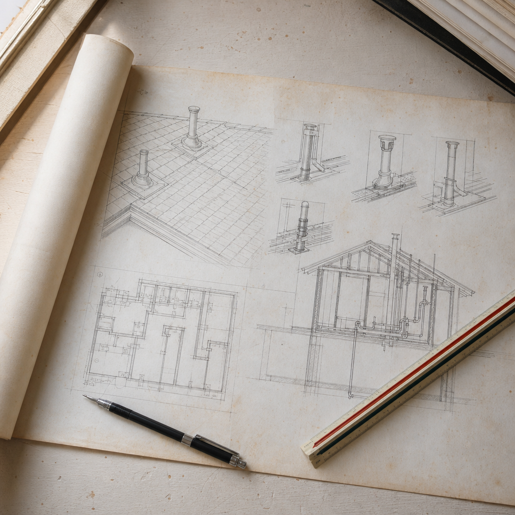
Code-compliant plumbing vent stack terminations on Alberta residential roof plans require rigorous attention to ABC clearances, detailed dimensioning, robust flashing assemblies, cross-disciplinary coordination, accurate code call-outs, and efficient responses to plan review and field RFIs. Each aspect of vent stack detailing-on roof plans, section drawings, detail sheets, and specs-must integrate design, building code requirements, material performance, and constructability to ensure system longevity and municipal approval.
ABC Clearances and Dimensioning Conventions for Vent Stacks on Residential Roof Plans
Clearance Requirements by ABC 7.5.6.5 and 7.5.6.6
Roof vent stack placement is governed by precise horizontal and vertical clearances in the Alberta Building Code, specifically ABC 7.5.6.5 and 7.5.6.6. The following distances are mandatory for any vent pipe terminal in Alberta:
- Operable Windows, Air Inlets, or Doors: Minimum 1 m vertically above, or 3.5 m in any direction from, doors, openable windows, or intakes (ABC 7.5.6.5). This prevents sewer gases from entering occupied spaces or HVAC systems.
- Roofs Supporting Occupancy: At least 2 m vertically above, or 3.5 m in any direction from, any accessible roof area, including decks and occupiable flat roofs.
- Ground Level: Terminals must rise at least 2 m above finished grade when not terminating above a building roof (rare in residential scenarios).
- Property Line: Minimum 1.8 m measured horizontally (ABC 7.5.6.6) from terminal to any property line; frequently enforced and often subject to redlines if missed.
Failure to achieve these clearances routinely triggers plan examiner comments such as: “Vent terminal location does not comply with ABC 7.5.6.6. Revise for 1.8m setback from property line.”
Dimensioning and Annotation on Roof Plans and Sections
Accurate, intelligible dimensioning is paramount:
- Plan View: Represent vent stacks as bold, unbroken circles or filled symbols. Annotate with pipe leader lines to identify the precise distance from the nearest wall, roof edge, parapet, or property line. For complex roofs, array exact setback dimensions between vent stack centerlines and adjacent windows or air inlets, typically offset in 100 mm increments to allow construction tolerances.
- Section Cuts: Show vent stack elevation above the finished roof deck, with vertical chain dimensions from roof membrane or shingle surface to vent terminal tip. Note increases in vent diameter where required for frost closure protection (see 7.5.6.5.(6)).
- Details: Use leader lines with arrowheads connecting to the outer circumference of the stack, never across the vent’s centerline, avoiding drawing clutter. For multiple penetrations, stagger call-out leader directions for clarity.
Layering conventions are crucial: vent stacks are typically shown on both plumbing/roof and structural plans, with unique CAD layers (‘VENT-ROOF’, ‘VENT-PLMR’), differentiated linetypes (e.g. continuous for visible, dashed for hidden below roof), and supporting numbering cross-references between plans and sections.
Common Plan-Review Redlines and Correction Methods
Frequent redlines at permit review include:
- “Vent too close to operable window/air intake.” Revise by shifting vent further along the roof plan and update dimensions and call-outs. In constrained footprints, adjust vent terminal elevation to achieve 1 m vertical above the window or 3.5 m diagonally.
- “Insufficient clearance to property line.” Rework roof routing to relocate the vent 1.8 m from side/rear yards, often requiring re-routing below the roof to an alternate exit apron, which must be dimensioned anew.
- “Section detail does not indicate vent height from roofing.” Revise sections to dimension vertical rise (minimum 150 mm by ABC 7.5.6.5.(5)(a)) and include notation for vent cap or frost closure requirements as per 7.5.6.5(6).
When revising, always coordinate plan, section, and detail references, updating numbering on both main sheets and the detail index. When adjusting vent locations, review all affected building envelope and insulation continuity details.
Material Specification Conventions
- Vent Pipe: Call out ABS or PVC (ASTM D2665/D1785 or CSA B181.1/B181.2). Indicate pipe increase to NPS 3 before roof penetration for main stacks where frost closure is a risk (per ABC 7.5.6.5.(6)).
- Flashing: Specify per ABC 7.2.10.14: copper, lead, aluminum, or 0.33 mm (26 ga) galvanized steel, with 125 mm flange minimums on pitched roofs. Explicitly note minimum flashing thickness in material schedules and detail references.
Material notes are best provided both in sectional details (“NPS 3 ABS vent, per ABC 7.5.6.5.(6)” or “26ga galv. steel flashing, 125mm min. flange”) and in the General Notes section (“All vent stack flashing per ABC 7.2.10.14 and 9.26.4.9.”).
Detailing Code-Compliant Vent Stack Flashing Assemblies for Various Roof Types
Code Requirements and Flashing Types
Watertight vent stack penetrations start with correct product specification and careful integration with the roofing assembly. The ABC (9.26.4.9) requires roof flashings for all pipes and ducts that penetrate the roof envelope, with at least 125 mm flange extensions on sloped roofs. Sealing air barrier continuity at penetrations is mandated by 9.36.2.11.(16), requiring a gasket, airtight flashing, or compatible tape or sealant bonded to the pipe and the plane of air tightness.
Standard flashing assemblies and key sheet call-outs include:
- EPDM Boot/Universal Roof Boot: “EPDM flexible boot to suit NPS X pipe, seal to underlayment membrane and overlap upper edge per ABC 9.36.2.11.(16).”
- Lead Flashing: “Lead flashing fitted tight to NPS 3 vent, extend flange min. 125 mm onto shingles, upturn min. 75 mm at uphill intersection.”
- Metal Counter-Flashing: “Prefinished 26 ga galvanised steel collar, hemmed at top edge, face-sealed with compatible polyether caulk.”
- Step Flashing (where vent is close to a sloped edge or wall): “26 ga galv. steel step flashing at each shingle course, interwoven with field shingles.”
Division 07 cross-references are crucial on detail sheets as code reviewers in Alberta expect to see reference to Section 07 60 00 (“Flashing and Sheet Metal”) or 07 92 00 (“Joint Sealants”) for joint/transition products at vent penetrations.
Integration with Roofing Systems
- Asphalt Shingle Roofing: Flashing flanges sit beneath upslope shingles and on top of down-slope courses; leader line note: “Install flange below upslope shingle per CRCA 9.4.4.”
- Metal Panel Roofing: Pipe boots sized to fit ribbed/standing-seam panels, with flexible metal or EPDM flange, sealed with butyl tape and screw-fastened into panel valleys.
- Low-Slope/Membrane Roofs: Prefab boots or on-site welded membrane collars, with clamping rings and a bead of membrane-compatible sealant (e.g., PMMA, modified bitumen adhesive) at all laps and interfaces. Typical detail call-out: “Welded membrane boot, integrate into top ply, clamp ring sealed and counterflashed with 150 mm curb.”
Material compatibility is noted within detail sheets and Division 07 specs, disallowing combinations that can induce galvanic corrosion (“Do not mix lead with aluminum; use all-galvanised system or EPDM universal boot for typed roofs”). On composite or low-slope roof assemblies, cross-reference the exact membrane product to the corresponding vent boot supplier details (“Firestone QuickSeam Pipe Flashing” or “Carlisle Sure-White TPO Pipe Boot”).
Drawing Conventions: Call-Outs, Details, and Coordination
- Detail Sheets: Provide both plan and section details for each flashing assembly. Exploded isometric views clarify layers: vent pipe, nailing flange, boot collar, membrane upturn, insulation, and vapor barrier extents shown in sequence.
- Section Cuts: Show vertical stacking-insulation butted close to collar, air barrier sealed and taped at pipe (notation per 9.36.2.11.(16)), boot collar height above membrane, and any required clamp ring. Dimension flange and upstand heights explicitly: “Flange: 125 mm min”; “Collar height above roof: 150 mm min.”
- Notes and Cross-References: On the general notes sheet: “Vent stack flashing and water-tight seal at all roof penetrations per ABC 9.26.4.9; coordinate with Division 07 60 00.”
Coordination details are cross-referenced in plan and elevation sheets: a standard call-out reads, “See Detail 3/A501 for vent stack termination & flashing.” Details should match the ventilation, architectural, and roofing sheets for consistency; discrepancies routinely generate city plan review delays.
Real-World Jobsite Installation Issues and Substitutions
Field substitutions and installation errors are common:
- Material Substitution: Generic pipe collars in lieu of specified boots-flag on field change order/addendum and supply updated detail clarifying product performance compliance, especially for complex roof geometries.
- Flashing Leaks on Steep Slopes: Insufficient flange upslope or omission of counterflashing. Field RFI: “Boot leaks at shingle interface, request clarification on correct lap sequence.” Response: sketch detail issued as supplemental, with note, “Extend flange 200 mm upslope, weave step flashing each course, lap boot collar below second course of shingles.”
- Thermal Expansion in Metal Roofs: “Pipe boot detached due to expansion of metal roof panel.” Field addendum: specify floating boot design with expansion collar and butyl sealant band.
Integrating ABC Code Reference Notes and Symbols into Plumbing & Roof Plan Sets
Annotation and Notation Strategies
Explicit ABC code integration within construction documents is both a code requirement and a powerful reviewer communication tool. Typical strategies include:
- Legend Development: Place a roof plan and plumbing plan legend quantifying all vent stack types, diameters, terminations, and accessory requirements. Each symbol includes a code reference, such as “O - Vent Stack (NPS 3 in), Frost Protection Required, per ABC 7.5.6.5.(6)(a).” Use unique symbol shapes to designate vent terminal types (open, capped, frost-protected) and coordinate across floor, roof, and detail sheets.
- Code Clause Call-Outs: Annotations adjacent to pipe runs and terminations reference explicit code text: “VENT (NPS 3) per ABC 7.5.4.1/7.5.6.5/7.5.6.6.” Inclusion of the full clause number (down to the tertiary digit) reduces review requests and clarifies compliance for field inspectors.
- General Notes Sheets:
- “All vent pipes to terminate not less than 150 mm above finished roof surface, per ABC 7.5.6.5.(5)(a).”
- “Where subject to frost closure, increase pipe size to minimum NPS 3 in before projecting through roof (ABC 7.5.6.5.(6)).”
- “No vent terminal within 1.8 m of property line or 3.5 m of air/combustion intake or operable window (ABC 7.5.6.6).”
Plan reviewers frequently flag missing or vague general notes: “Plumbing Notes do not reference ABC Section 7.5. Add explicit height and setback requirements to note block.”
Detail and Schedule Call-Outs
- Drawing Sheet Call-Outs: “VENT STACK (NPS 3) - See 5/A602, Install per ABC 7.5.6.5.(6),” allows tracing vent requirements from plan to isometric and to specific code provision. Schedule columns indicate “ABC Ref #” for cross-verification at review.
- Pipe Sizing: On plan sheets, annotate each stack with pipe size, developed length, and fixture units served. ABC 7.5.8.3 governs sizing: “Vent stack NPS 1½ for up to 9 m developed, serving [X] FUs.” City reviewers routinely return plans with redlines such as, “Show vent sizing and fixture unit calc per ABC 7.5.8.3.”
- Height and Frost Notes: At each roof section, dimension vent stack projection “> 150 mm above roof,” and annotate, “Frost closure: NPS 3 min. per ABC 7.5.6.5.(6)(a).” Where snow accumulation risk is high, note “Increase stack by additional 150 mm above expected drift zone.”
What Plan Reviewers Seek: Code Integration and Quality Control
Municipal building plan reviewers expect:
- Every code-mandated vent clearance, height, and size called out by ABC section/subsection.
- Consistent scheduling of pipe material and diameter, with indication that ABC 7.2.5 material standards are met.
- Vent terminations highlighted on all relevant floor, roof, and isometric sheets, not solely plumbing isometrics.
- No “or equal” or vague standards for vent height or setback-explicit, numeric dimensioning is necessary, referencing both code and as-built performance (snow drift zones, prevailing wind exposure).
Omission of these annotations results in comments such as: “Insufficient data to verify vent terminal code compliance. Add requirement for height above snow drift and note on frost closure protection.” Revisions must address these head-on, updating all affected drawing sheets and global notes to prevent ongoing delays.
Structural and Thermal Envelope Coordination for Vent Stack Penetrations
Structural Detailing and Framing Coordination
Structural design must safeguard truss, rafter, and panel integrity at every vent stack penetration:
- Truss and Rafter Avoidance: Roof plans must position vent stacks away from primary truss webs/rafters. Standard note: “Field verify truss layout. Relocate vent stack if required to maintain truss uncut-coordinate with structural drawings S202.”
- Blocking/Framing at Large Penetrations: For oversized vents (NPS 4 and above), show added double headers or trimmed joists, detailed in sections (“Provide double 2x6 trimmer/headers both sides of vent chase; simpson H1 truss clips every side”). Coordination clouding between architectural and structural sheets ensures changes propagate to all platforms.
- RFI Hotspot: Framing crews often request supplemental clarifications due to conflicts not resolved in design: “Vent stack location conflicts with main girder truss-request offset routing or sleeve/box-out detail.” Issuing an addendum detail, with red-clouded area on plan and full section cut through the adjusted location, expedites field resolution.
Where cutting any structural member is unavoidable (which should be rare and justified), explicit engineered repair details are provided with stamped approval, otherwise the plan will be returned with: “Unengineered truss cut at vent. Revise and provide sealed repair.”
Thermal and Air/Vapor Barrier Continuity at Penetrations
The ABC’s thermal and air barrier requirements (9.25, 9.36) directly impact vent stack detailing:
- Air Barrier Sealing: “Seal air barrier membrane to vent pipe using Siga Fentrim tape or Tremco acoustical sealant, per ABC 9.36.2.11.(16). Install EPDM penetration gasket encased at roof deck plane.” Isometric penetration details layer each building envelope component, from interior finish, through vapor barrier, insulation, sheathing, membrane, then boot/gasket and exterior flashing.
- Continuous Insulation: Insulation batts or spray foam must tightly surround the vent stack chase at attic floor/ceiling interface. Section note: “Fill all voids around vent with R22 batt insulation, minimum 50 mm from vent pipe per ASTM E814. Maintain total attic insulation depth per ABC 9.36.2.8.” Where rigid foam board is breached, show cut-to-fit inserts packed around pipe penetration.
- Moisture Management: Prevent condensation at cold stacks within unconditioned attic by requiring pipe insulation for high-diameter vents. “Wrap vent with pipe insulation min. R4.2, 1 m both above and below roof deck.”
Envelope and penetration details must be referenced back to overall building section drawings; section “B/A201” is cited in both envelope and roofing details for clarity on insulation overlaps and sealing sequence. Typical RFI: “How is vapor barrier continuity maintained at vent penetration? Please provide detailed sketch.”
Drawing Coordination and Field Documentation
- Penetration Details: “Detail 7/A502 - Vent Penetration at Sloped Trussed Roof”. Enlarged (1:5 or 1:2) detail with labeled call-outs for each envelope and structural element, including all sealant types and fastener patterns. Number all detail references consistently in plan and section legends for cross-checking during shop drawing and site review stages.
- General Note Example: “All pipe penetrations to be fully air and vapor sealed per ABC 9.36.2.11, using self-adhesive membrane and caulk. Maintain minimum effective RSI at penetration within 10% of surrounding ceiling per ABC 9.36.2.8.”
- Typical Plan-Review Redline: “Clarify detail at vent penetration - missing insulation/sealant information. Revise and resubmit with full envelope continuity detail.”
Responding to Plan Review Redlines and Jobsite RFIs for Vent Stack Terminations
Common Plan-Review Redlines and Efficient Revision Practices
Plan-checking authorities focus scrutiny on:
- “Vents too close to property line.” Root cause: missed/ambiguous dimension on plan. Correction: move vent, update all involved plans, detail sheets, and dimension ticks. Confirm the new dimension is shown to the property line and label as “1.8 m min. per ABC 7.5.6.6.”
- “Missing height above snow load.” Especially important in Alberta where snow drift can reach >600 mm. Fix involves revising section detail to increase vent projection above roof deck by at least 150 mm (some local authorities require 600 mm where heavy drift is expected), with note: “EXTEND VENT MINIMUM 600 mm ABOVE ANTICIPATED DRIFT LINE.”
- “Flashing detail insufficient for roof pitch.” Abstract, non-specific flashing call-outs create inspection ambiguity. Corrected by revising detail for the exact roof pitch in question (e.g., “For 8:12 shingle roof, upturn boot collar 150 mm, lap step flashing under two upslope shingle courses, per CRCA 9.4.4-1”).
When revising, digital clouding is recommended on all changed sheets, with revision logs referencing the redline item number and specific code articles satisfied.
Jobsite RFIs and Field Resolution Process
Common RFI scenarios and how drafters respond:
- Structural Conflict (Site RFI: “Vent conflicts with truss T5 at grid E.”): Drafter issues a revised plan with the vent shifted-detail bubble and “R0X” revision code, updated dimension to adjacent wall/tie point, and a new section sketch for alternate routing. Field Sketch (“SK-03”) attached as addendum to clarify revised penetration detail and revised truss layout if required.
- Non-Standard Roof Condition (Site RFI: “Multi-pitch intersection at vent stack transition. No standard detail supplied.”): Drafter produces a supplemental 3D isometric and overlay detail showing vent transition through valley/hip intersection, with explicit lateral offset dimensions and step/counterflashing sequence for all roof planes.
- Frost Closure or Cold Stack RFI (“Observed frost inside stack, insulation incomplete at attic”): Issue an amplified insulation detail, specifying “Pipe insulation R4.2, both sides of attic floor, extend 1 m from penetration. Increase pipe to NPS 3 if not already present.” Reference ABC 7.5.6.5.(6)(a) in the issued clarification.
Responses must be comprehensive and coordinated-any change impacts envelope, insulation, structural, and sometimes mechanical drawings. Addenda and supplemental sketches reference all affected original sheet numbers and update the General Notes block.
Implications of Drawing Changes and Subsequent Documentation
- Major vent relocation: downstream effect on plumbing isometrics, roof structure, and penetrations through insulation and vapor barriers. Required to be checked and clouded on every referenced drawing.
- Flashings on a revised pitch: check for material substitution implications. For example, moving from a 4:12 shingle roof to a 2:12 membrane roof alters the entire boot/flashing assembly-update Division 07 specs and all penetration details.
- Plan review resubmissions: include a summary letter or index noting all revised sheet numbers, redlined items addressed, and explicit ABC clause numbers referenced for each corrected item.
Conclusion: Integrated Detailing for Code-Compliant Vent Stack Terminations
Architectural drafting for plumbing vent stack terminations in Alberta involves multi-layered detail: rooting every dimension and annotation in explicit ABC code references, standardizing meaningful flashing assemblies suited to the exact roof system, and thoroughly coordinating penetrations with both the structural layout and the building envelope’s air and thermal barriers. Effective integration of code call-outs, robust notation, and detail references- combined with a proactive approach to redlines and field RFIs-ensures that plumbing vent systems are both lawful and buildable.
With detailed plan integration and responsive documentation, Kingsway Drafting & Design provides compliance-centric, constructable roof plan solutions for Alberta homes and developments.