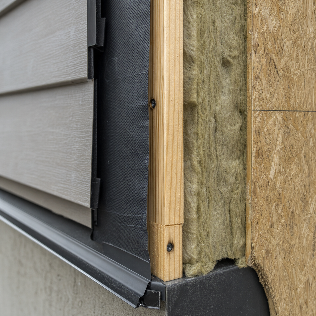
Precision in weather-resistive barrier (WRB) and drainage plane detailing is not just an expectation but a necessity in Alberta residential construction, demanded by the 2023 Alberta Building Code (ABC) and reinforced by real-world plan review and site QA. High-performing wall assemblies emerge when code translation, plan notation, and jobsite execution align seamlessly.
WRB Continuity Under Alberta Building Code: Drawing Conventions, Notes, and Specified Assemblies
Code Pathways and Drawing Integration
Alberta’s 2023 NBC sets explicit requirements for WRB continuity, notably in Section 9.27. The drafter’s responsibility is to move these directives from dense code text into actionable, reviewable, and buildable documentation, using language and sheet conventions that preempt costly redlines.
- Section 9.27.2.1 requires exterior walls to be constructed “to minimize precipitation ingress and prevent damage due to moisture.”
- 9.27.2.3 describes the “first plane” (cladding) and the “second plane” (WRB) of protection, emphasizing a continuous, unbroken WRB layer behind all cladding systems.
- 9.27.3.3.(2) prescribes specific WRB lapping: “Sheathing membranes shall be lapped not less than 100 mm horizontally and 150 mm vertically.”
- 9.27.3.7 & 9.27.3.8 detail flashing material gauges and minimum slopes, governing both selection and orientation in details.
Real-world translation onto plan sheets:
- General Note: “All exterior walls to be protected with a continuous sheathing membrane installed in accordance with NBC(AE) 9.27.3.3. Laps: 100 mm horizontal, 150 mm vertical.”
- Key Plan Call-out: “WRB CONTINUOUS, SEE 2/A4.3 FOR TYPICAL LAP AND TERMINATION DETAIL.”
- Flashing Note: “Galvanized steel flashing, 0.33 mm min thickness, 6% min slope to exterior, end dams 25 mm high. NBC(AE) 9.27.3.8.”
General notes must also reference sheathing membrane standards (“Conform to CAN/CGSB-51.32-M per NBC(AE) 9.27.3.2”) and call out perm ratings, where applicable for climate-appropriate vapor permeability (typ. 10-20 perms for Alberta).
Assembly Specification and Material Schedules
Selection of membrane, tapes, fasteners, and flashings should be organized in written specifications, with cross-reference to code-driven dimensions and ratings.
- Sheathing Membrane: Min. 10 perms, typical commercial-grade breather, conforming to CAN/CGSB-51.32-M. Spec sheet to indicate compatibility with sheathing and cladding fasteners.
- Flashing: Select from:
- Galvanized steel, 0.33 mm
- Copper, 0.46 mm
- Aluminum, 0.48 mm
- Vinyl, 1.02 mm
- Sealants: Non-hardening, exterior-grade, compatible with WRB membranes and adjacent cladding, per NBC(AE) 9.27.4.2.
Legible, measured assembly sections (“SCALE: 1:5”), should designate air barrier/WRB lineweight, include dimension callouts for lap (100 mm, 150 mm), and note fastener spacing if not specified elsewhere.
Typical Plan-Review Redlines and Preventive Detail Conventions
- Comment: “Specific detail missing for WRB transition over foundation insulation-provide enlarged detail.”
- Redline: “Flashing at parapet does not show 6% slope-revise detail 4/A6.2.”
- Correction: “Sheathing membrane lapping not dimensioned-add dimensions per NBC(AE) 9.27.3.3.(2).”
To minimize these, embed detail references (“TYP. WRB/FLASHING LAP, SEE 6/A5.1”) and use keynotes for every assembly intersection or complex transition, maintaining consistent notation standards across all sheets.
Dimension and Spec Examples (on Plan/Detail Sheets)
- Horizontal WRB Lap: “LAP (horiz): 100 mm MIN.”
- Vertical WRB Lap: “LAP (vert): 150 mm MIN.”
- End Dams: “END DAM: 25 mm MIN. HEIGHT.”
- Flashing Slope: “6% SLOPE TOWARD EXTERIOR.”
Routinely include material spec tables referencing WRB product codes, membrane perm ratings, and fastener types/intervals, as reviewed and accepted by local code authorities (NBC(AE) 2023 Alberta Edition).
Fenestration Detailing: WRB & Flashing Continuity at Openings - Windows, Doors, and Lapped Protection
Code-Driven Window and Door Opening Protocol
Water intrusion risk peaks at fenestration. The NBC’s Section 9.27.3.3 and successive subsections (9.27.3.7, 9.27.3.8) mandate a “second plane of protection” at all openings, requiring pan flashings at sills, precise head flashings, robust jamb integration, and proper end dams.
Window and Door Sill Pan Flashing:
- Code: “Pan flashing required at sill, sealed or sloped to direct water toward exterior (NBC(AE) 9.27.3.3).”
- Dimension: Typical back dam height, min. 6 mm (1/4”). End dams extend vertically to block lateral bypass.
- Plan-detail call out: “SILL PAN WITH 6 mm BACK DAM, END DAMS CONT., SEE 7/A6.1.”
Head Flashing, Drip Cap, and WRB Overlap:
- Flashing heads must project min. 6” (152 mm) past window jambs to shed runoff beyond opening scope.
- WRB to be lapped over head flashing not less than 50 mm (2”), shingle style (“Install WRB over head flashing-min. 50 mm lap. NBC(AE) 9.27.3.3”).”
Jamb Integration: Side flashing integrates into WRB/air barrier using self-adhered membranes (AAMA 711) or liquid-applied flashings (AAMA 714), tightly lapped at junction to reject water at jamb-interface.
Typical Drawing Notations and Redline Triggers
- Plan Note: “WINDOW OPENING TO RECEIVE FULL SILL PAN FLASHING, END DAMS, CONT. AIR SEAL AROUND FRAME, SHEET 9/A7.1.”
- Material Call-Out: “USE GALVANIZED STEEL FOR ALL HEAD AND SILL FLASHINGS, MIN 0.33 mm, END DAMS 25 mm.”
- Install Sequence Note: “SHINGLE-FASHION WRB OVER FLASHING COMPONENTS.”
Comments observed in municipal reviews include:
- “Head flashing detail does not show WRB overlap-revise detail 8/A8.2.”
- “Sill detail missing pan/back dam; resubmit.”
- “Specify minimum head flashing extension both directions from jamb.”
All opening details should be cross-referenced on plan elevations (“TYP. WINDOW SILL/HEAD/JAMB FLASHING, SEE DETAILS 6-8/A6.2”). Provide section and isometric details for one typical window and door each, including:
- Sill pan with back and end dams
- Head flashing extended and WRB overlap
- Jamb with membrane continuity
Real-World Dimensional Integration
- Sill pan back dam: 6 mm min, measured from inner sill face.
- Head flashing extension: 152 mm min past each jamb face.
- Flashing lap: 50 mm WRB over top leg of flashing.
All call-outs should reference current standards (“Self-adhered membrane: AAMA 711, window/door sills; Liquid-applied: AAMA 714 at complex transitions.”).
Cladding-Specific Drainage Planes: Detailing Cavities, Weep Systems, and Termination Solutions
Drainage Cavity and Furring: Stucco, Siding, Masonry Veneer
Drainage plane detailing changes with cladding type. For vented wood siding, fiber-cement, or engineered panels, NBC(AE) 9.27.5.3 governs furring: “Use furring not less than 19 mm by 38 mm, fastened to studs not more than 600 mm apart.” These details appear on assembly wall sections and are essential to drainage continuity and cladding support.
Masonry veneer, as per 9.20.13.2, demands an uninterrupted 25 mm min. air space between veneer and substrate-dimensioned and color-coded in section details (“25 mm CAVITY-SEE MASONRY VENEER, WALL SECTION 9/A3.5”).
For stucco, 5 mm min. drainage mat or cavity is best practice in Moist A and Marine C zones. Alberta’s temperature swings and rain-on-snow events make drainage cavities critical, even when not strictly enforced at every project by code.
Weep Screed and Termination Detailing
At the bottom of stucco or masonry walls, water must be able to exit the cavity. Weep screeds-noted as “Galv. steel, 3.5” (89 mm) vertical flange, at min. 150 mm (6”) above grade”-should be sectioned and detailed with leader notes: “WEEP SCREED, 3.5” FLANGE, DRAIN SLOT UNOBSTRUCTED, CLEARANCE TO GRADE MIN 150 mm. SEE 2/A7.3.”
Where brick veneer meets grade, insect screens are shown in enlarged details and keyed as “STAINLESS STEEL INSECT SCREEN OVER 25 mm DRAINAGE CAVITY.” Laying out these transitions with measured call-outs minimizes “weep blocked by landscaping” plan review citations.
Dimension References on Cladding Details
- Wood/Panel Furring: 19 x 38 mm
- Furring Spacing: Not more than 600 mm o.c.
- Masonry Veneer Cavity: 25 mm clear
- Stucco Drainage Mat: 5 mm min
- Weep Screed Flange: 89 mm (3.5”)
- Clearance to Grade: 150 mm-200 mm (6”-8”)
Section tags and detail markers standardized: “TYP. STUCCO BASE, SEE 7/A6.5.”
CRITICAL JUNCTURES: WRB & Drainage Integration at Transitions and Penetrations
Wall-to-Foundation: Grade Clearance & Damp Proofing Overlap
Grade clearance to cladding (200 mm typical for wood, per industry and local practice) should be dimensioned in wall/foundation sections and called out: “150 mm (6”) MIN. TO FIN. GRADE, WOOD CLADDING; 50 mm (2”) TO NON-WOOD CLADDINGS.”
Dampproofing of the foundation (NBC(AE) 9.13.2.1) must run from top of footing to finished ground; wall section notes: “DAMPPROOFING, TIES INTO WRB ABOVE, LAP 50 mm MIN., SEAL JOINT.” Comment redlines often cite: “WRB not shown overlapping or sealed to top of dampproofing-revise 5/A2.0.”
Wall-to-Roof: Kick-Outs, Step Flashings, and Integration
Roof-wall intersections with eaves or sloped rooflines are chronic leak points without proper flashings. Kick-out flashings (per NBC(AE) 9.26.4.1) are shown exiting wall 50 mm past outer edge, funnelling all roof runoff clear of cladding; detail bubble: “4/A6.6.”
Step flashings (9.26.4.2) lap each other by 50 mm, rise 100 mm up the wall, bridged by WRB lapped over uppermost flashing. Drawing notation: “STEP FLASHING, 24 GA. GALV. STL., 50 mm LAP, MIN 100 mm UP WALL, FASTEN AS PER MANUFACTURER.”
Jobsite QA almost always notes missing or under-dimensioned step and kick-out flashing at the first course-these should be detailed at plan and roof sections with explicit assembly phasing (“INSTALL STEP FLASHING W/ EACH SHINGLE COURSE, KICK-OUT @ STARTER ROW”).
Service Penetrations: Pipes, Vents, Electrical, and WRB Continuity
All penetrations are detailed in both wall sections and isometrics, calling for:
- “SELF-ADHERED MEMBRANE WRAP, EXTEND 100 mm PAST PIPE/O.D., SEAL W/ ELASTOMERIC SEALANT, NBC(AE) 9.27.3.3.”
- “PIPE COLLAR FLASHING, GALV. STL., INTEGRATE INTO WRB.”
- For fire-rated walls, “PENETRATION TO BE FIRESTOPPED, F-RATING EQUAL TO ASSEMBLY.”
Plan Review & Jobsite QA: Strategies for Error-Free WRB & Drainage Documentation
Proactive Detailing to Ensure Code and Site Compliance
Detailing rigorously at the drafting stage eliminates WRB/drainage ambiguities that become expensive RFIs or low-scope rejections at plan review or during site inspection.
- Zoomed details (1:5, 1:10 scale) for every WRB termination, window/door opening, and foundation/roof interface.
- Plan sheet notation: “MINIMUM WRB LAP 100 mm HORIZ / 150 mm VERT-SEE DETAILS 2-4/A6.1.”
- Slope and grading noted: “10% MIN SLOPE (200 mm drop over 2 m) FROM FOUNDATION-SEE SITE PLAN S2.1.”
Documenting Revisions and Effective Project Communication
Consistent use of revision clouds and tagged revision notes (“Rev 03: Updated WRB overlap, added sill pan sections-07/06/24”) is expected by plan reviewers and required for field QA. Cross-check drawing registers and key plans to ensure all updates propagate downstream.
Jobsite RFIs and QA punchlists often surface “field-solved” solutions: e.g., additional sealant at unplanned electrical conduit, or on-site modification to step flashing at attic knee wall. These solutions should trigger immediate CAD revision and master detail update (“ADDED TAPE AT CONDUIT PENETRATION-NOTE IN STD DETAIL 5/A8.3 FOR FUTURE PROJECTS”).
Dimensional Summary Table (for Drawing Inclusion)
- WRB Lap (Horiz): 100 mm min
- WRB Lap (Vert): 150 mm min
- Flashing Extension (Up Wall): 50 mm min
- Head Flashing Projection: 152 mm (6”) min each side
- Furring Strips: 19 x 38 mm min, 600 mm o.c. max
- Drainage Slope: 200 mm over 2 m (10%) from foundation
- Grade Clearance (Cladding): 150-200 mm
- Masonry Cavity: 25 mm
Drawing-Sheet Conventions & Review-Ready Notation
- Standard detail call-outs: “5/A6.1, 6/A6.1, 7/A6.3” for all repeat transition types
- Graphic symbols: Consistent hatching for WRBs, flashings, and furring across all sections/elevations
- Revision schedule: Track with clouded changes, full descriptions, and cross-index to plan note updates
Conclusion
Effective weather-resistive barrier and drainage plane documentation in Alberta residential design pivots on code-literate translation, precise dimensioning, and proactive QA from plan sheets to jobsite fieldwork. Each intersection, transition, and opening must be deliberately drawn, called out, and scheduled in alignment with Section 9.27 and related ABC requirements, as well as with real, pragmatic builder and inspector feedback. The outcome: fewer redlines, stronger permit approvals, and assemblies that perform for decades in Alberta’s challenging climate.
For envelope assemblies that move seamlessly from design through inspection, Kingsway Drafting & Design delivers code-ready drafting detail for every Alberta residential project.