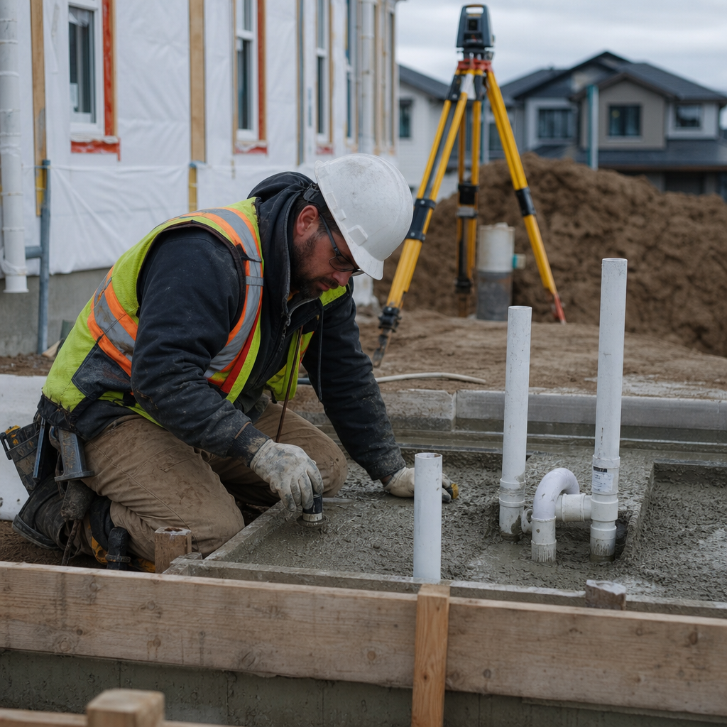
Code-compliant sump pump discharge systems play a central role in Alberta residential foundations, affecting multiple drawing sheets, redlines, site inspections, and permit approvals. From specifying pump and pit characteristics in the basement plan to dimensioning discharge pipe routings on the site plan, and detailing foundation penetrations and backup systems, proper integration is essential to avoid the recurring headaches of compliance failures and inspection call-backs.
Detailing Internal Sump Discharge Plumbing & Electrical Rough-ins
Sump Pit Placement and Pit Dimensioning
Basement drain control begins with clear depiction of the sump pit location and size. NBC(AE) 9.14.5.2.(1) requires residential sump pits to be at least 750 mm (30 inches) deep and have a minimum area of 0.25 m2 (2.7 square feet). Drawing conventions call for plans to coordinate the sump pit’s position as close to the exterior wall as achievable-ideally within 1.2 m-on the downstream or lowest side of the basement, supporting positive gravity flow from any under-slab drainage.
Plan sheets typically call out the pit with a standardized symbol and leader, e.g.:
- “SUMP PIT, 750 mm D x 600 mm Ø, c/w perforated liner, airtight child-resistant cover per NBC(AE) 9.25.3.3.(7).”
Typical plan-review comments in Alberta include:
- “Pit size not labeled, does not appear to meet minimum 0.25 m2 area.”
- “Show clear dimension from pit to foundation wall.”
Pump Selection, Performance, and Operation Call-outs
Primary pump specifications are critical for functional and inspection requirements. Call-outs must indicate:
- Type: submersible or column-type accepted; submersible preferable for sealed, covered pits.
- Capacity/Head: e.g., “Pump rated min. 100 LPM @ 3.0 m head, auto float switch.”
ABC plan reviewers may query unlabelled pump sizing, especially for larger homes or areas with high water tables.
Discharge Pipe Sizing, Material, and Routing
For internal discharge piping, NBC(AE) 9.14.5.2.(2) sets a 32 mm (1.25”) minimum diameter. However, 38-50 mm (1.5-2”) PVC/ABS piping is typical on Alberta plans for reliability. Pipe runs should be detailed up the wall, with bends minimized and mechanical supports specified every 1.2m horizontally/1.5m vertically to prevent vibration. The following detail call-out avoids plan reviewer redlines:
- “1.5” ABS Sch40 discharge pipe, secured to wall w/ vibration-isolating straps at 1.2m O.C., 45° sweep at transitions; pipe under slab where possible.”
Material specification notes and section details cut through the pit, with clear elevation dimensions showing pipe rise and exit points. Review and construction redlines arise when:
- Pipe material not coordinated with plumbing legend/spec.
- Pipe exit route and clearance from other services unreconciled.
Check Valve, Unions, and Anti-Siphon/Weep Hole Detailing
A check valve is mandatory to prevent pumped water from returning once the pump switches off-its omission is a universal plan review failure. Standard call-out:
- “1.5” swing check valve c/w union, installed within 1.0 m of pit; anti-siphon hole (3 mm dia.) drilled in pipe below check valve, above pit waterline.”
Section details should show both valve and anti-siphon hole location, with ballooned notes. Reviews note missing anti-siphon holes or inaccessible valves as a code deviation and demand revision.
Electrical Rough-in and GFCI Circuit Notes
Sump pump electrical feed requires special attention under CEC (Rule 26-658):
- Dedicated 15A circuit (labeled at panel).
- GFCI-protected receptacle within cord length above highest water level, never shared with other loads.
Drawing standards include on electrical plans:
- “15A, 120V dedicated circuit to sump w/ GFCI, located 300mm above pit cover, per Canadian Electrical Code Rule 26-658.”
Plan reviewers and electrical inspectors redline circuits lacking GFCI notation, or non-dedicated runs.
Vibration and Noise Control Notes
Pumps transmit vibration unless specifically addressed. Standard notes to limit occupancy complaints include:
- “Discharge pipe to be fitted with rubber isolation coupler at pump exit and vibration-damping pipe clamps at all supports.”
Sections and details in the mechanical schedule should call out these components explicitly to avoid field change directives during site inspection.
Drawing Sheet Conventions and Cross-references
Coordination between plan and section is critical for clarity. Best practice uses:
- Sump plan location marker referencing “Detail 1/MP-104.”
- Legend notation for each component (e.g., sump, pump, check valve, anti-siphon, GFCI outlet).
- Section balloons referencing wall and pipe outlets in section views.
Foundation Wall Penetration & Frost-Protected Exterior Transition Details
Sleeve Material, Size, and Placement
Properly dimensioned wall penetrations accommodate movement and facilitate reliable sealing. Drawings denote sleeves as follows:
- “100 mm PVC sleeve (min. 25 mm annular gap) for 1.5” discharge pipe, centered not less than 200 mm from edge of foundation.”
PVC or HDPE is preferred for most residential penetrations unless soil or engineer’s instructions specify steel. The sleeve must extend through the full wall thickness with 25 mm+ projection each side for sealing bead application.
Waterproof and Airtight Sealing Methods
ABC 2023 Section 9.13 requires all penetrations to be dampproofed/waterproofed. Standard detail for these transitions:
- “Seal annular space with polyurethane mastic, surface tooled to shed water; install mechanical pipe seal or gasket if specified by engineering.”
- In radon-prone areas, “Apply radon-resistant elastomeric sealant, overlap with foundation gas barrier membrane per NBC(AE) 9.13.4.3.”
Field redlines almost always result from missing or ambiguous sealing notes, especially on multiple penetrations clustered together.
Frost Protection and Insulation Details
Pipes traversing below or through the foundation must be protected from Alberta’s common 1.2 m+ frost depths (Calgary) and up to 1.5 m (Edmonton). Wall section details and notes address both internal and external insulation:
- “Pipe to be continuously insulated with closed-cell foam sleeve, minimum R-4 per inch, extended from pit to 1 m past exterior wall.”
- “Horizontal rigid insulation board (min. R-10, 1 m wide) applied over pipe burial to extend frost barrier.”
Plan review comments cite omitted insulation or pipes terminating above frost depth as critical risks for freezing failures.
Dimensioning Foundation Penetrations and Relative Elevations
Section and elevation details must document precise heights to coordinate with slab, grade, and exit conditions. Standard dimensions include:
- Penetration at least 150 mm above floor slab (for backflow prevention).
- Exterior exit min. 150 mm above final grade, unless otherwise protected.
- Not less than 200 mm horizontally from wall corners or structural elements.
Plan reviewers frequently note “penetration too low; revise to maintain 150 mm min. above grade.”
Section Details and Enlarged Penetration Illustrations
Best practice includes a 1:5 or 1:10 enlarged detail of the pipe wall penetration, showing:
- Pipe within sleeve, insulation, continuous interior/exterior sealant bead, and wall waterproofing membrane wrap.
- Labeling: “See Detail 4/S-302: Sump Discharge Pipe Wall Exit.”
Cross-referenced in plan and noted in the drawing legend, these are key for clear contractor instruction and inspection sign-off.
Site Plan Detailing for Exterior Discharge Routes & Minimum Clearances
Pipe Route, Surface Grading, and Slope Requirements
Exterior routing must prevent standing water or backflow, which means sloped runs to grade-even for pressurized discharge. Best practice, though not codified in NBC(AE) Part 9, is a 1% slope for non-pressurized drain sections, called out directly on the site/grading plan:
- “1.5” discharge: 1% min. slope, continuous to termination.”
Where the pipe is exposed before burial, coordinate with the landscape plan to avoid compaction and erosion.
Bury Depths for Frost Protection and Pipe Specifications
Drainage pipes must be protected from extreme Alberta frost depths. While NBC(AE) 9.31.2.2.(1) applies to water services, it serves as guidance: bury at least 150 mm below local maximum frost, which ranges from 1.2-2.4 m regionally. Use of 100 mm (4”) minimum diameter pipes in CSA-rated PVC, ABS, or HDPE is standard; schedule 40 rigid wall required for vehicular areas. Plan sheets call out material and burial:
- “Bury 1.5” discharge pipe 1.2 m min. below grade or insulate w/ extruded polystyrene, 50mm thick, if above frost.”
Plan reviewer redlines and site inspection failings typically result from insufficient cover and non-rated materials in driveways.
Termination Device Detailing and Erosion Control
Termination requires slowing the water and directing it away from foundations, walkways, and property lines. On plan:
- “Discharge to concrete splash pad, 600x400 mm, sloped away from building.”
- “Optional: Pop-up emitter or dry well, refer Detail 8/CIV-201.”
All termination features are labeled with leader notes and referenced on grading/drainage details for inspection.
Minimum Clearance Dimensions: Structures, Property, and Openings
Clearances are critical for code and bylaw compliance-most cited for plan review and inspection failures. Alberta municipalities typically enforce (see local bylaw references):
- 1.5 m min. discharge setback to property line.
- 1.2 m min. to adjacent buildings.
- 0.6 m min. from windows and exterior doors.
- 3 m min. from air intakes/HVAC.
- 1 m min. from walkways and driveways; never discharge across public ROWs.
Dimension call-outs must be shown on the site plan with labeled leaders and overlays:
- “Sump discharge terminates 1.5m from property line, 3.1m from air intake, per local bylaw.”
Common plan check redlines include:
- “Discharge shown within 1.0 m of P/L; move to comply with 1.5 m setback.”
- “Revise pipe route to clear egress window by >600 mm.”
Plan Conventions: Symbols, Line Types, and Detail References
Conventions demand a clear graphical approach:
- Solid lines for existing utilities, dashed for new; heavy for below-grade, light for above-grade.
- Standard pipe symbol with arrows for flow direction; triangular leader for splash pad or emitter.
- Each feature cross-referenced to a site or grading detail: “See Detail 11/CIV-301.”
Material and Installation Notes on Plans
Every site plan must include material call-outs and installation notes, such as:
- “All exterior sumps and drains: PVC SDR35 min., 1% slope, granular bedding, compacted in 150 mm lifts.”
- Insulate above-frost pipes with 50 mm polystyrene (R-10 min.), extend 1 m horizontally over pipe.”
Drafting Considerations for Backup Sump Systems & Alarms
Backup/Battery Pump System Detailing
Designing for flood resilience demands specifying backup pumping with clarity for installation and review. Most backup pumps (12V DC, deep cycle battery, 4-12 hours runtime) are positioned beside or above the primary pump-never in contact to avoid vibration.
Drawings must indicate if the backup connects to a distinct discharge line or tees into the primary, with each branch fitted with a check valve. Standard notation:
- “Install secondary battery-powered sump on separate 1.5” discharge w/ independent check valve, union, and termination; label all in pump legend.”
Some designs permit shared discharge with dual check valves before the junction; elevate this at plan review to avoid RFI confusion.
Battery, Charging Unit, and Electrical Coordination
Backups require battery locations with clear access, ventilation, and proximity to a 120V GFCI-protected outlet for the charger. Drawings show battery within an elevated enclosure, never below high water line. Detail sections/an enlarged pump room diagram label:
- “Deep cycle 12V battery on shelf, charger plug in 120V GFCI nearby; panel and circuit labeled ‘Sump Backup’.”
CEC requires backup sump circuits to follow same electrical protection levels as primary, with dedicated lines and GFCI/AFCI as appropriate.
Common reviewer comments note “battery location not shown” or “no outlet for charger-revise electrical plan.”
Water Level Alarm Integration
Plan sets must show the type and location of high-water alarms (wired or wireless), alarm horn, and potential home automation tie-in:
- “Install float-switch high water alarm, wired to 120V audible alarm at top of pit and main panel; optional wireless transmitter to homeowner’s device.”
Electrical plans mark the alarm on the home run diagram. Omission triggers plan review and, ultimately, field inspection deficiencies.
Plan Call-outs and Maintenance Testing Notes
System longevity depends on maintenance, testing, and user comprehension. Standard general notes call for:
- “Sump pump and alarm to be tested monthly; replacement batteries every 2 years or as per manufacturer.”
These maintenance notes are typically added as “General Requirements” under plumbing or basement notes on A-sheets or M-sheets.
Navigating Plan Review Redlines & Jobsite Call-outs for Sump Pump Compliance
Recurring Review Comments and Solutions
Documented throughout Alberta municipalities are the following redlines, reliably caught at review:
- Check Valve Missing: “Install a check valve on the sump pump discharge line to prevent backflow.” Solution: Show location on section and call-out at plan with leader and note, e.g., “1.5” check valve, accessible, downstream of union.”
- Discharge Distance Non-Compliant: “Discharge terminates less than 1.5 m from foundation-revise.” Solution: Dimensioned discharge run, labeled, with cross reference to splash pad detail.
- Unsealed Penetrations: “Seal all sump pump discharge pipe penetrations to maintain the integrity of the building envelope.” Solution: Detailed wall penetration detail and sealed call-outs on both plan and section sheets.
- Prohibited Discharge Direction: “Redirect sump pump discharge to prevent water from draining onto adjacent properties.” Solution: Update site plan to show discharge flagged 90° away from side property line and terminate at correct distance.
- Missing Anti-Siphon Hole: “Provide an anti-siphon hole in the discharge pipe to prevent air lock.” Solution: Ballooned note on section: “Drill 3 mm anti-siphon hole below check valve, above water line.”
Frequently Failed Jobsite Inspection Items
Common on-site call-outs during Alberta site inspections:
- Check valve missing or installed inside pit, inaccessible.
- Discharge not terminating the required 1.5 m from foundation and instead discharging directly onto grade.
- Unsealed wall penetrations allowing ground moisture ingress (especially at walk-out basements).
- Discharge directed toward neighbour’s lot, sidewalk, or street opening-severe violation under municipal bylaw, rarely signed off.
- No visible anti-siphon hole, or incorrect placement causing pump air lock.
Drawing sheet conventions to preempt these failures rely on a split detail format-plan with dimensioned route and section cuts; enlarged penetration/seal detail with leader notes; general notes covering review-triggering requirements.
Frequent Contractor RFI/Clarification Queries and Preemptive Notes
Contractor queries most often target:
- “What type and spec of check valve is required?” - Solution: Legend entry: “1.5” swing-type PVC check valve, corrosion-resistant, union port at downstream.”
- “Where exactly does discharge pipe penetrate the wall?” - Solution: Dimension on basement plan and section “100 mm above slab, 150 mm above finished grade exterior, 200 mm clear of foundation corner."
- “Does wall penetration need insulation or frost protection?” - Solution: Section detail balloon: "Continuous closed-cell foam insulation through and 1m past foundation wall.”
- “Is it code to have the discharge pipe above or below frost line?” - Solution: Site/section note: “Discharge pipe buried min. 1.2 m below grade or insulated with R-10 exterior board as per local frost depth data.”
- “How do I size and install backup pump battery?” - Solution: Detail: “Deep cycle AGM battery, 12V, 75Ah min., on elevate rack, in ventilated compartment per M-302.”
Sample Drawing Notes to Avoid Common Failures
- “SUMP PUMP SYSTEM: Consists of 1/2 HP primary submersible with float, 1.5” ABS discharge c/w check valve, anti-siphon hole, dedicated 15A GFCI circuit, airtight pit cover, and exterior discharge per site plan.”
- “BACKUP BATTERY SUMP: 12V DC, separate check valve and float. Battery located on elevated shelf above pit; commercial-grade charger GFCI-protected.”
- “All discharge pipes: Min. 1.5m from foundation and property line, terminate at splash pad; no discharge to street, lane, or neighbouring property.”
- “Wall penetration at 150 mm above highest finished grade, sleeved, sealed all sides with polyurethane sealant, insulated to frost protection standard.”
Revision clouds and callouts must highlight all updates in response to review redlines, providing clear before/after sheet log references to speed re-submission and field review confirmation.
Summary
Comprehensive drafting and detailing of sump pump discharge routes and connections in Alberta residential construction requires careful attention to code-prescribed dimensions, pipe materials, penetration and insulation details, external routing, system redundancy, alarm integration, and meticulous notation. Cross-sheet coordination, proper sectioning, and standardized terminology are the critical lines of defense against project delays and recurrent inspection failures. For each element, drawing-specific call-outs and supplementary details-anchored in Alberta Building Code, Canadian Electrical Code, and local bylaws-ensure a smoother plan review, clearer communication with contractors, and a better-performing final product.
Kingsway Drafting & Design is committed to precision, compliance, and clarity in every Alberta residential plan we produce.